engine oil RENAULT SCENIC 2010 J95 / 3.G Petrol Injection S3000 Injection Workshop Manual
[x] Cancel search | Manufacturer: RENAULT, Model Year: 2010, Model line: SCENIC, Model: RENAULT SCENIC 2010 J95 / 3.GPages: 230, PDF Size: 0.92 MB
Page 11 of 230

PETROL INJECTION
Fault finding - System operation
17B
17B - 11
PETROL INJECTION
Fault finding - System operation
17B
17B - 11V9 MR-372-J84-17B050$094.mif
S3000 Injection
Program No.: AD
Vdiag No.: 4C / 54
Adaptive idling speed correction:
Under normal warm operating conditions, the idling speed opening cycle ratio value PR091 Idling speed regulation
theoretical OCR varies between a high value and a low value to obtain the nominal idling speed.
After operating dispersion (running in, engine fouling, etc.), the opening cycle ratio value may be close to the high or
low values.
The adaptive correction PR090 Idling speed regulation programming value on the idling speed opening cycle
ratio compensates for the gradual variations in the engine's air requirement, by bringing the idling speed opening
cycle ratio back to an average nominal value.
This adjustment only takes effect if the coolant temperature is above 75 °C, 1 minute after starting the engine and
during the idle speed regulation phase.
Idling speed setpoint calculation:
The idling speed setpoint is given by parameter PR010 Idle speed regulation valve setpoint.
The idling speed regulation setpoint depends on the coolant temperature, the depollution programming, the climate
control requirements, the position of the gearbox selector, any power assisted steering action, the passenger
compartment heating resistors, the oil temperature (engine protection) and the electricity balance calculated by the
injection software (the engine speed is increased by 160 rpm maximum if the battery voltage remains below 12.7 V).
Richness management
For optimal operation of the catalytic converter, the richness must be maintained around 1.
Richness regulation is controlled by the upstream sensor. The sensor gives voltage according to the difference
between the partial oxygen pressures contained in the exhaust and a cavity filled with a reference mixture
(atmosphere).
As the partial oxygen pressure in the exhaust is representative of the richness, the voltage supplied to the computer
represents a Rich - Lean signal.
Adaptive richness correction:
In loop mode, the richness regulation corrects the injection duration in order to obtain a mixture which is as close as
possible to a richness of 1. The richness correction value PR138 Richness correction is close to 50 %, with limits
of 0 and 100 %.
The richness adaptive corrections PR143 Self-adapting richness gain and PR144 Self-adapting richness offset
are used to offset the injection mapping to centre richness regulation on 50 %.
Adaptive corrections take 50 % as an average value after computer initialisation (clearing the programming) and have
the following limit values:
Page 51 of 230
PETROL INJECTION
Fault finding - Interpretation of faults
17B
17B-51
PETROL INJECTION
Fault finding - Interpretation of faults
17B
17B-51V9 MR-372-J84-17B050$329.mif
S3000 Injection
Program No.: AD
Vdiag No.: 4C / 54
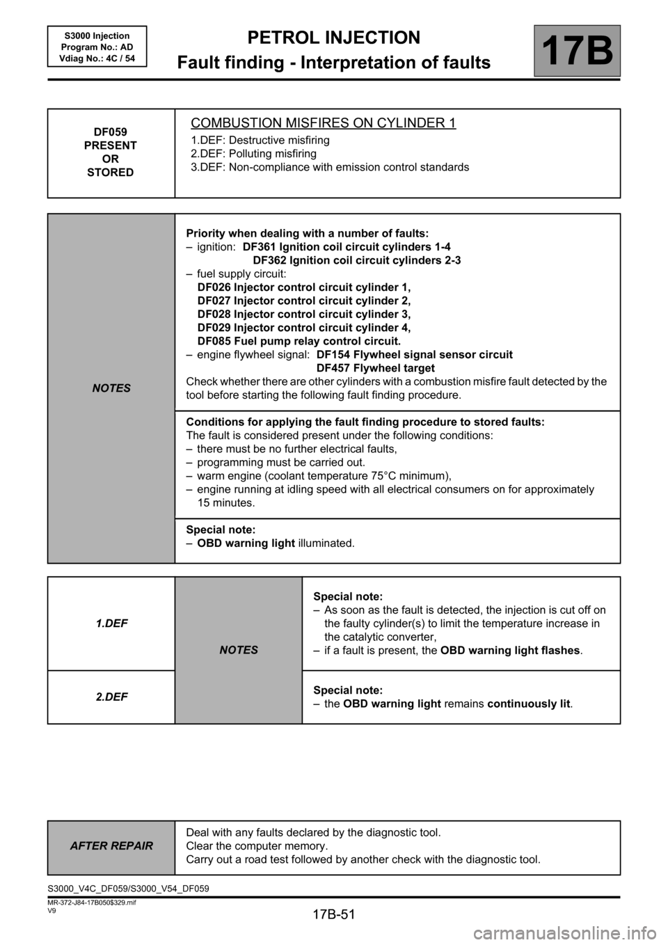
DF059
PRESENT
OR
STOREDCOMBUSTION MISFIRES ON CYLINDER 1
1.DEF: Destructive misfiring
2.DEF: Polluting misfiring
3.DEF: Non-compliance with emission control standards
NOTESPriority when dealing with a number of faults:
– ignition: DF361 Ignition coil circuit cylinders 1-4
DF362 Ignition coil circuit cylinders 2-3
– fuel supply circuit:
DF026 Injector control circuit cylinder 1,
DF027 Injector control circuit cylinder 2,
DF028 Injector control circuit cylinder 3,
DF029 Injector control circuit cylinder 4,
DF085 Fuel pump relay control circuit.
– engine flywheel signal: DF154 Flywheel signal sensor circuit
DF457 Flywheel target
Check whether there are other cylinders with a combustion misfire fault detected by the
tool before starting the following fault finding procedure.
Conditions for applying the fault finding procedure to stored faults:
The fault is considered present under the following conditions:
– there must be no further electrical faults,
– programming must be carried out.
– warm engine (coolant temperature 75°C minimum),
– engine running at idling speed with all electrical consumers on for approximately
15 minutes.
Special note:
–OBD warning light illuminated.
1.DEF
NOTESSpecial note:
– As soon as the fault is detected, the injection is cut off on
the faulty cylinder(s) to limit the temperature increase in
the catalytic converter,
– if a fault is present, the OBD warning light flashes.
2.DEFSpecial note:
–the OBD warning light remains continuously lit.
AFTER REPAIRDeal with any faults declared by the diagnostic tool.
Clear the computer memory.
Carry out a road test followed by another check with the diagnostic tool.
S3000_V4C_DF059/S3000_V54_DF059
Page 52 of 230

PETROL INJECTION
Fault finding - Interpretation of faults
17B
17B-52
PETROL INJECTION
Fault finding - Interpretation of faults
17B
17B-52V9 MR-372-J84-17B050$329.mif
S3000 Injection
Program No.: AD
Vdiag No.: 4C / 54
DF059
CONTINUED
Misfiring on
cylinder 1 only
Combustion
misfires in
cylinders 1 and 4
(see DF059
Combustion
misfires in
cylinder 1 and
DF062 Combustion
misfires in
cylinder 4)
Combustion
misfires on all four
cylinders (see
DF060, DF061 and
DF062)
The fault is probably due to a component that can only affect this cylinder:
– check the cylinder 1 pencil coil,
– check the condition and conformity of the spark plugs,
– check the cylinder 1 injector
If everything is in order, check the same components on cylinder 4 (to cover a possible
cylinder recognition error).
The fault is probably due to a component that affects a pair of cylinders:
– check the ignition coil circuit concerned (apply the interpretation of fault DF361
Ignition coil control 1-4),
– check the condition and conformity of the spark plugs.
The fault is probably due to a component affecting all the cylinders:
– check that the correct fuel is being used,
– check the condition and conformity of the spark plugs.
If the fault is still present, carry out the following checks:
– check the flywheel sensor,
– check the condition and cleanliness of the flywheel,
– check the flywheel sensor mounting,
– check the sensor/flywheel air gap,
– check the cylinder compressions,
– check the complete fuel system (see MR 364 or 370 Mechanics, 13A, Fuel supply, Petrol supply system),
– check the complete ignition system (see MR 364 or 370 Mechanics, 17A, Ignition, Spark plugs),
– check the hydraulic tappets if there is camshaft noise (see MR 364 or 370 Mechanics, 11A, Top and front of
engine).
If the fault is still present, deal with the other faults then proceed with the conformity check.
AFTER REPAIRDeal with any faults declared by the diagnostic tool.
Clear the computer memory.
Carry out a road test followed by another check with the diagnostic tool.
Page 53 of 230
PETROL INJECTION
Fault finding - Interpretation of faults
17B
17B-53
PETROL INJECTION
Fault finding - Interpretation of faults
17B
17B-53V9 MR-372-J84-17B050$329.mif
S3000 Injection
Program No.: AD
Vdiag No.: 4C / 54
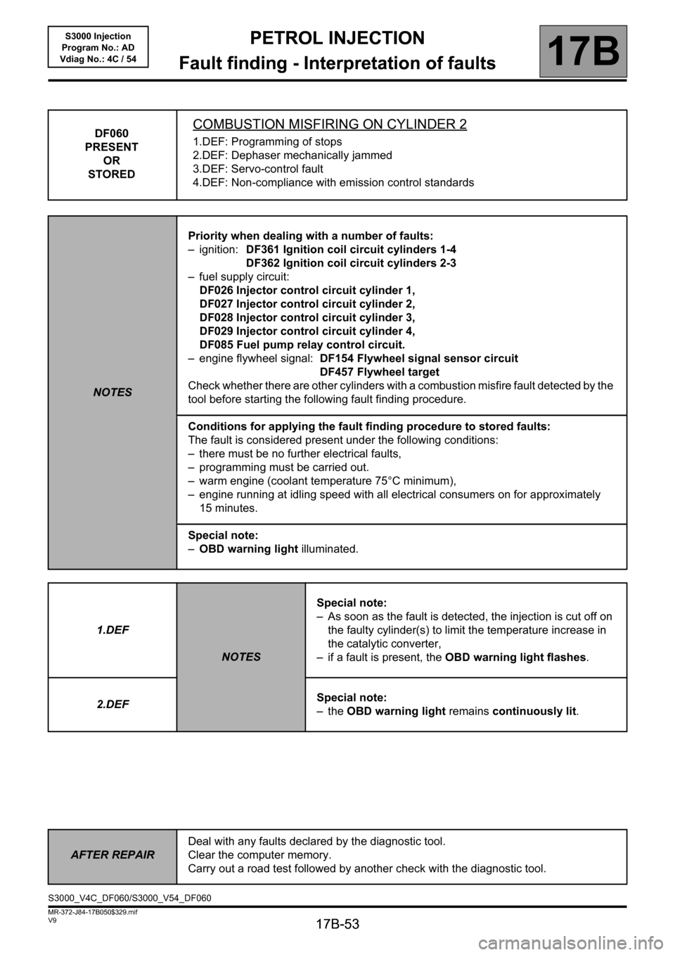
DF060
PRESENT
OR
STOREDCOMBUSTION MISFIRING ON CYLINDER 2
1.DEF: Programming of stops
2.DEF: Dephaser mechanically jammed
3.DEF: Servo-control fault
4.DEF: Non-compliance with emission control standards
NOTESPriority when dealing with a number of faults:
– ignition: DF361 Ignition coil circuit cylinders 1-4
DF362 Ignition coil circuit cylinders 2-3
– fuel supply circuit:
DF026 Injector control circuit cylinder 1,
DF027 Injector control circuit cylinder 2,
DF028 Injector control circuit cylinder 3,
DF029 Injector control circuit cylinder 4,
DF085 Fuel pump relay control circuit.
– engine flywheel signal: DF154 Flywheel signal sensor circuit
DF457 Flywheel target
Check whether there are other cylinders with a combustion misfire fault detected by the
tool before starting the following fault finding procedure.
Conditions for applying the fault finding procedure to stored faults:
The fault is considered present under the following conditions:
– there must be no further electrical faults,
– programming must be carried out.
– warm engine (coolant temperature 75°C minimum),
– engine running at idling speed with all electrical consumers on for approximately
15 minutes.
Special note:
–OBD warning light illuminated.
1.DEF
NOTESSpecial note:
– As soon as the fault is detected, the injection is cut off on
the faulty cylinder(s) to limit the temperature increase in
the catalytic converter,
– if a fault is present, the OBD warning light flashes.
2.DEFSpecial note:
–the OBD warning light remains continuously lit.
AFTER REPAIRDeal with any faults declared by the diagnostic tool.
Clear the computer memory.
Carry out a road test followed by another check with the diagnostic tool.
S3000_V4C_DF060/S3000_V54_DF060
Page 54 of 230

PETROL INJECTION
Fault finding - Interpretation of faults
17B
17B-54
PETROL INJECTION
Fault finding - Interpretation of faults
17B
17B-54V9 MR-372-J84-17B050$329.mif
S3000 Injection
Program No.: AD
Vdiag No.: 4C / 54
DF060
CONTINUED
Combustion
misfires in
cylinder 2 only
Misfires in
cylinders 2 and 3
(see DF060
Misfires in
cylinder 2 and
DF061 Misfires in
cylinder 3)
Combustion
misfires on all
four cylinders
(see DF059, DF060
DF061 and DF062)
The fault is probably due to a component that can only affect this cylinder:
– check the cylinder 2 pencil coil,
– check the condition and conformity of the spark plugs,
– check the cylinder 2 injector.
If everything is in order, check the same components on cylinder 3 (to correct a possible
cylinder identification error).
The fault is probably due to a component that affects a pair of cylinders:
– check the ignition coil circuit concerned (apply the interpretation of fault DF362
Ignition coil control 2-3),
– check the condition and conformity of the spark plugs.
The fault is probably due to a component affecting all the cylinders:
– check that the correct fuel is being used,
– check the condition and conformity of the spark plugs.
If the fault is still present, carry out the following checks:
– check the flywheel sensor,
– check the condition and cleanliness of the flywheel,
– check the flywheel sensor mounting,
– check the sensor/flywheel air gap,
– check the cylinder compressions,
– check the complete fuel system (see MR 364 or 370 Mechanics, 13A, Fuel supply, Petrol supply system),
– check the complete ignition system (see MR 364 or 370 Mechanics, 17A, Ignition, Spark plugs),
– check the hydraulic tappets if there is camshaft noise (see MR 364 or 370 Mechanics, 11A, Top and front of
engine).
If the fault is still present, deal with the other faults then proceed with the conformity check.
AFTER REPAIRDeal with any faults declared by the diagnostic tool.
Clear the computer memory.
Carry out a road test followed by another check with the diagnostic tool.
Page 55 of 230
PETROL INJECTION
Fault finding - Interpretation of faults
17B
17B-55
PETROL INJECTION
Fault finding - Interpretation of faults
17B
17B-55V9 MR-372-J84-17B050$329.mif
S3000 Injection
Program No.: AD
Vdiag No.: 4C / 54
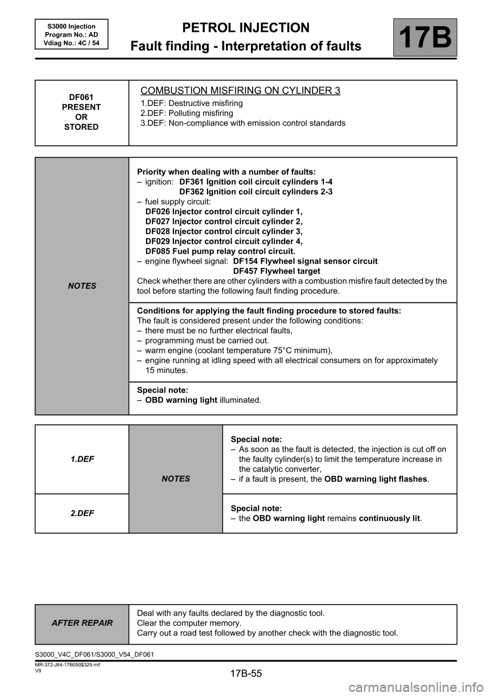
DF061
PRESENT
OR
STOREDCOMBUSTION MISFIRING ON CYLINDER 3
1.DEF: Destructive misfiring
2.DEF: Polluting misfiring
3.DEF: Non-compliance with emission control standards
NOTESPriority when dealing with a number of faults:
– ignition: DF361 Ignition coil circuit cylinders 1-4
DF362 Ignition coil circuit cylinders 2-3
– fuel supply circuit:
DF026 Injector control circuit cylinder 1,
DF027 Injector control circuit cylinder 2,
DF028 Injector control circuit cylinder 3,
DF029 Injector control circuit cylinder 4,
DF085 Fuel pump relay control circuit.
– engine flywheel signal: DF154 Flywheel signal sensor circuit
DF457 Flywheel target
Check whether there are other cylinders with a combustion misfire fault detected by the
tool before starting the following fault finding procedure.
Conditions for applying the fault finding procedure to stored faults:
The fault is considered present under the following conditions:
– there must be no further electrical faults,
– programming must be carried out.
– warm engine (coolant temperature 75°C minimum),
– engine running at idling speed with all electrical consumers on for approximately
15 minutes.
Special note:
–OBD warning light illuminated.
1.DEF
NOTESSpecial note:
– As soon as the fault is detected, the injection is cut off on
the faulty cylinder(s) to limit the temperature increase in
the catalytic converter,
– if a fault is present, the OBD warning light flashes.
2.DEFSpecial note:
–the OBD warning light remains continuously lit.
AFTER REPAIRDeal with any faults declared by the diagnostic tool.
Clear the computer memory.
Carry out a road test followed by another check with the diagnostic tool.
S3000_V4C_DF061/S3000_V54_DF061
Page 56 of 230

PETROL INJECTION
Fault finding - Interpretation of faults
17B
17B-56
PETROL INJECTION
Fault finding - Interpretation of faults
17B
17B-56V9 MR-372-J84-17B050$329.mif
S3000 Injection
Program No.: AD
Vdiag No.: 4C / 54
DF061
CONTINUED
Combustion
misfires in
cylinder 3 only
Misfires in
cylinders 2 and 3
(see DF060
Misfires in
cylinder 2 and
DF061 Misfires in
cylinder 3)
Combustion
misfires on all
four cylinders
(see DF059, DF060
DF061 and DF062)
The fault is probably due to a component that can only affect this cylinder:
– check the cylinder 3 pencil coil,
– check the condition and conformity of the spark plugs,
– check the cylinder 3 injector.
If everything is in order, check the same components on cylinder 2 (to correct a possible
cylinder identification error).
The fault is probably due to a component that affects a pair of cylinders:
– check the ignition coil circuit concerned (apply the interpretation of fault DF362
Ignition coil 2-3 control),
– check the condition and conformity of the spark plugs.
The fault is probably due to a component affecting all the cylinders:
– check that the correct fuel is being used,
– check the condition and conformity of the spark plugs.
If the fault is still present, carry out the following checks:
– check the flywheel sensor,
– check the condition and cleanliness of the flywheel,
– check the mounting of the flywheel sensor,
– check the flywheel/sensor air gap,
– check the cylinder compressions,
– check the complete fuel system (see MR 364 or 370 Mechanics, 13A, Fuel supply, Petrol supply system),
– check the complete ignition system (see MR 364 or 370 Mechanics, 17A, Ignition, Spark plugs),
– check the hydraulic tappets if there is camshaft noise (see MR 364 or 370 Mechanics, 11A, Top and front of
engine).
If the fault is still present, deal with the other faults then proceed with the conformity check.
AFTER REPAIRDeal with any faults declared by the diagnostic tool.
Clear the computer memory.
Carry out a road test followed by another check with the diagnostic tool.
Page 57 of 230
PETROL INJECTION
Fault finding - Interpretation of faults
17B
17B-57
PETROL INJECTION
Fault finding - Interpretation of faults
17B
17B-57V9 MR-372-J84-17B050$329.mif
S3000 Injection
Program No.: AD
Vdiag No.: 4C / 54
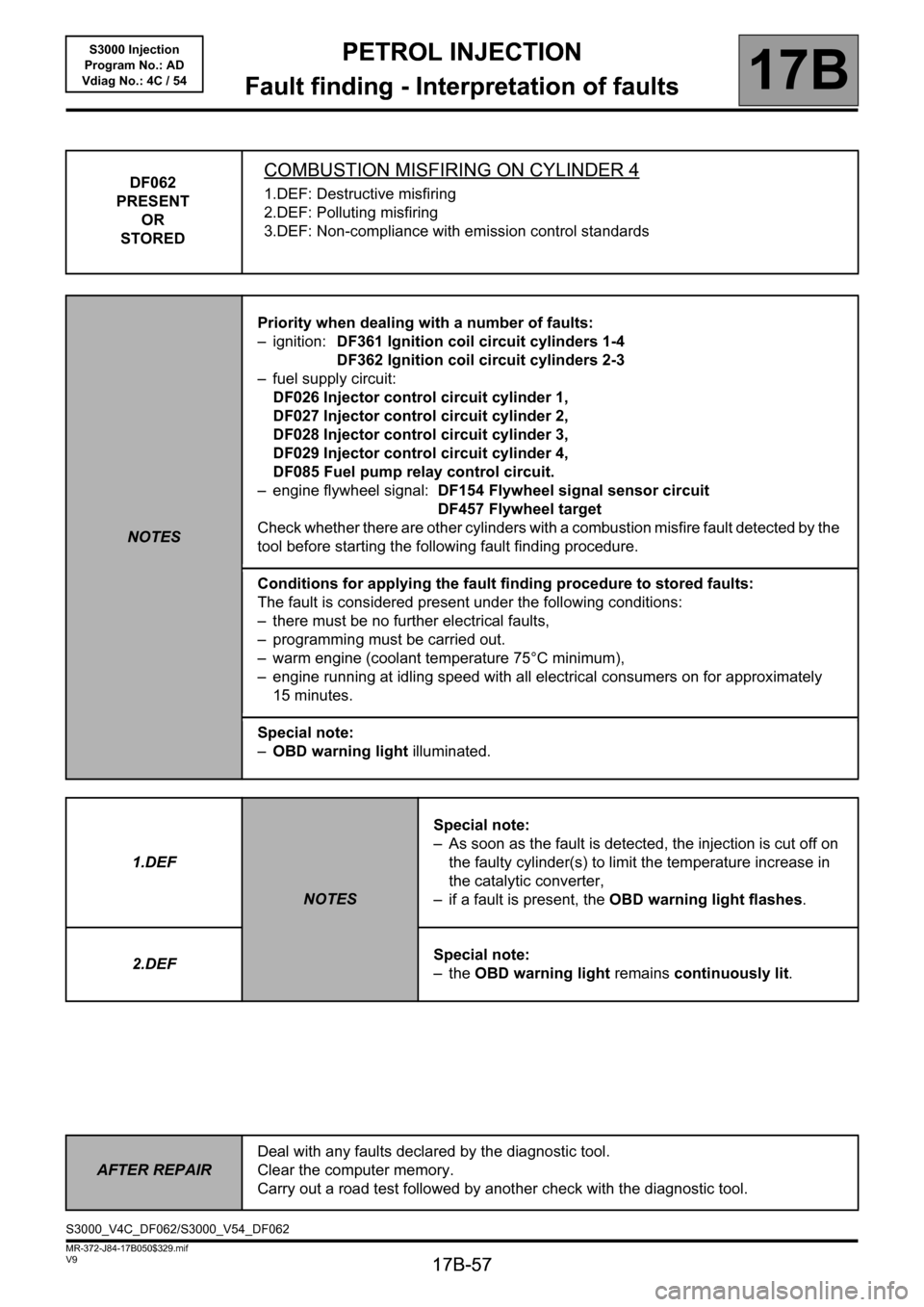
DF062
PRESENT
OR
STOREDCOMBUSTION MISFIRING ON CYLINDER 4
1.DEF: Destructive misfiring
2.DEF: Polluting misfiring
3.DEF: Non-compliance with emission control standards
NOTESPriority when dealing with a number of faults:
– ignition: DF361 Ignition coil circuit cylinders 1-4
DF362 Ignition coil circuit cylinders 2-3
– fuel supply circuit:
DF026 Injector control circuit cylinder 1,
DF027 Injector control circuit cylinder 2,
DF028 Injector control circuit cylinder 3,
DF029 Injector control circuit cylinder 4,
DF085 Fuel pump relay control circuit.
– engine flywheel signal: DF154 Flywheel signal sensor circuit
DF457 Flywheel target
Check whether there are other cylinders with a combustion misfire fault detected by the
tool before starting the following fault finding procedure.
Conditions for applying the fault finding procedure to stored faults:
The fault is considered present under the following conditions:
– there must be no further electrical faults,
– programming must be carried out.
– warm engine (coolant temperature 75°C minimum),
– engine running at idling speed with all electrical consumers on for approximately
15 minutes.
Special note:
–OBD warning light illuminated.
1.DEF
NOTESSpecial note:
– As soon as the fault is detected, the injection is cut off on
the faulty cylinder(s) to limit the temperature increase in
the catalytic converter,
– if a fault is present, the OBD warning light flashes.
2.DEFSpecial note:
–the OBD warning light remains continuously lit.
AFTER REPAIRDeal with any faults declared by the diagnostic tool.
Clear the computer memory.
Carry out a road test followed by another check with the diagnostic tool.
S3000_V4C_DF062/S3000_V54_DF062
Page 58 of 230

PETROL INJECTION
Fault finding - Interpretation of faults
17B
17B-58
PETROL INJECTION
Fault finding - Interpretation of faults
17B
17B-58V9 MR-372-J84-17B050$329.mif
S3000 Injection
Program No.: AD
Vdiag No.: 4C / 54
DF062
CONTINUED
Misfiring on
cylinder 4 only
Combustion
misfires in
cylinders 1 and 4
(see DF059
Combustion
misfires in
cylinder 1 and
DF062 Combustion
misfires in
cylinder 4)
Combustion
misfires on all four
cylinders (see
DF059, DF060
DF061 and DF062)
The fault is probably due to a component that can only affect this cylinder:
– check the pencil coil of cylinder 4,
– check the condition and conformity of the spark plugs,
– check the cylinder 4 injector
If everything is okay, check the same components on cylinder 1 (to correct a possible
cylinder identification error).
The fault is probably due to a component that affects a pair of cylinders:
– check the ignition coil circuit concerned (apply the interpretation of fault DF361
Ignition coil control 1-4),
– check the condition and conformity of the spark plugs.
The fault is probably due to a component affecting all the cylinders:
– check that the correct fuel is being used,
– check the condition and conformity of the spark plugs.
If the fault is still present, carry out the following checks:
– check the flywheel sensor,
– check the condition and cleanliness of the flywheel,
– check the flywheel sensor mounting,
– check the flywheel/sensor air gap,
– check the cylinder compressions,
– check the complete fuel system (see MR 364 or 370 Mechanics, 13A, Fuel supply, Petrol supply system),
– check the complete ignition system (see MR 364 or 370 Mechanics, 17A, Ignition, Spark plugs),
– check the hydraulic tappets if there is camshaft noise (see MR 364 or 370 Mechanics, 11A, Top and front of
engine).
If the fault is still present, deal with the other faults then proceed with the conformity check.
AFTER REPAIRDeal with any faults declared by the diagnostic tool.
Clear the computer memory.
Carry out a road test followed by another check with the diagnostic tool.
Page 94 of 230
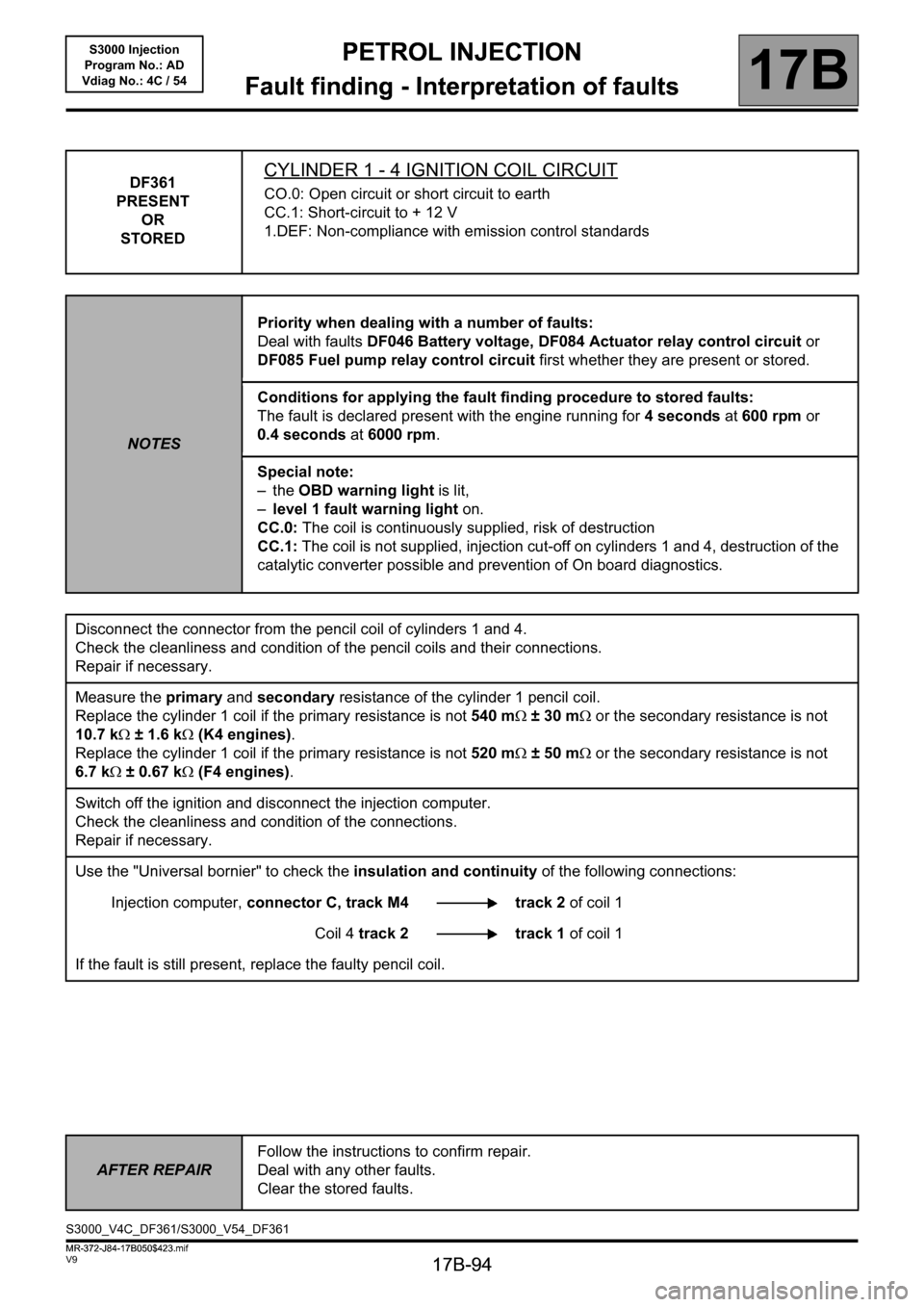
PETROL INJECTION
Fault finding - Interpretation of faults
17B
17B-94
PETROL INJECTION
Fault finding - Interpretation of faults
17B
17B-94V9 MR-372-J84-17B050$423.mif
S3000 Injection
Program No.: AD
Vdiag No.: 4C / 54PETROL INJECTION
Fault finding - Interpretation of faults
DF361
PRESENT
OR
STOREDCYLINDER 1 - 4 IGNITION COIL CIRCUIT
CO.0: Open circuit or short circuit to earth
CC.1: Short-circuit to + 12 V
1.DEF: Non-compliance with emission control standards
NOTESPriority when dealing with a number of faults:
Deal with faults DF046 Battery voltage, DF084 Actuator relay control circuit or
DF085 Fuel pump relay control circuit first whether they are present or stored.
Conditions for applying the fault finding procedure to stored faults:
The fault is declared present with the engine running for 4 seconds at 600 rpm or
0.4 seconds at 6000 rpm.
Special note:
–the OBD warning light is lit,
–level 1 fault warning light on.
CC.0: The coil is continuously supplied, risk of destruction
CC.1: The coil is not supplied, injection cut-off on cylinders 1 and 4, destruction of the
catalytic converter possible and prevention of On board diagnostics.
Disconnect the connector from the pencil coil of cylinders 1 and 4.
Check the cleanliness and condition of the pencil coils and their connections.
Repair if necessary.
Measure the primary and secondary resistance of the cylinder 1 pencil coil.
Replace the cylinder 1 coil if the primary resistance is not 540 mΩ ±30mΩ or the secondary resistance is not
10.7 kΩ ± 1.6 kΩ (K4 engines).
Replace the cylinder 1 coil if the primary resistance is not 520 mΩ ±50mΩ or the secondary resistance is not
6.7 kΩ ± 0.67 kΩ (F4 engines).
Switch off the ignition and disconnect the injection computer.
Check the cleanliness and condition of the connections.
Repair if necessary.
Use the "Universal bornier" to check the insulation and continuity of the following connections:
Injection computer, connector C, track M4 track 2 of coil 1
Coil 4 track 2 track 1 of coil 1
If the fault is still present, replace the faulty pencil coil.
AFTER REPAIRFollow the instructions to confirm repair.
Deal with any other faults.
Clear the stored faults.
S3000_V4C_DF361/S3000_V54_DF361
MR-372-J84-17B050$423.mif