air conditioning RENAULT SCENIC 2011 J95 / 3.G Engine And Peripherals EDC16 Injection User Guide
[x] Cancel search | Manufacturer: RENAULT, Model Year: 2011, Model line: SCENIC, Model: RENAULT SCENIC 2011 J95 / 3.GPages: 236, PDF Size: 1.32 MB
Page 147 of 236
13B - 147
DIESEL INJECTION
Fault finding - Status summary table13B
V10 MR-372-J84-13B150$517.mif
EDC16 INJECTION
Program No.: C1
Vdiag No.: 44, 48 and 4CDIESEL INJECTION
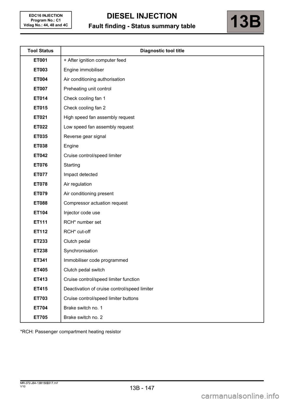
Fault finding - Status summary table
*RCH: Passenger compartment heating resistorTool Status Diagnostic tool title
ET001+ After ignition computer feed
ET003Engine immobiliser
ET004Air conditioning authorisation
ET007Preheating unit control
ET014Check cooling fan 1
ET015Check cooling fan 2
ET021High speed fan assembly request
ET022Low speed fan assembly request
ET035Reverse gear signal
ET038Engine
ET042Cruise control/speed limiter
ET076Starting
ET077Impact detected
ET078Air regulation
ET079Air conditioning present
ET088Compressor actuation request
ET104Injector code use
ET111RCH* number set
ET112RCH* cut-off
ET233Clutch pedal
ET238Synchronisation
ET341Immobiliser code programmed
ET405Clutch pedal switch
ET413Cruise control/speed limiter function
ET415Deactivation of cruise control/speed limiter
ET703Cruise control/speed limiter buttons
ET704Brake switch no. 1
ET705Brake switch no. 2
MR-372-J84-13B150$517.mif
Page 150 of 236
DIESEL INJECTION
Fault finding - Interpretation of statuses13B
13B-150V10 MR-372-J84-13B150$564.mif
EDC16 INJECTION
Program No.: C1
Vdiag No.: 44, 48 and 4C
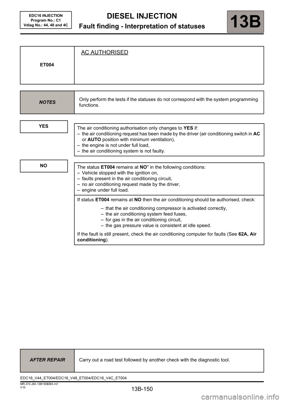
ET004
AC AUTHORISED
NOTESOnly perform the tests if the statuses do not correspond with the system programming
functions.
YES
NO
The air conditioning authorisation only changes to YES if:
– the air conditioning request has been made by the driver (air conditioning switch in AC
or AUTO position with minimum ventilation),
– the engine is not under full load,
– the air conditioning system is not faulty.
The status ET004 remains at NO" in the following conditions:
– Vehicle stopped with the ignition on,
– faults present in the air conditioning circuit,
– no air conditioning request made by the driver,
– engine under full load.
If status ET004 remains at NO then the air conditioning should be authorised, check:
– that the air conditioning compressor is activated correctly,
– the air conditioning system feed fuses,
– for gas in the air conditioning circuit,
– the gas pressure value is consistent at idle speed.
If the fault is still present, check the air conditioning computer for faults (See 62A, Air
conditioning).
AFTER REPAIRCarry out a road test followed by another check with the diagnostic tool.
EDC16_V44_ET004/EDC16_V48_ET004/EDC16_V4C_ET004
Page 152 of 236

13B-152
DIESEL INJECTION
Fault finding - Interpretation of statuses13B
V10 MR-372-J84-13B150$564.mif
EDC16 INJECTION
Program No.: C1
Vdiag No.: 44, 48 and 4C
ET014
FAN ASSEMBLY 1 CHECK
NOTESOnly perform the tests if the statuses do not correspond with the system programming
functions.
Note: Status ET022 Low-speed engine fan request and status ET014 Engine fan assembly check 1 change
their status at the same time.
RUNNING
The low-speed fan assembly is supplied in three scenarios:
– the engine coolant temperature is above 89°C,
– the air conditioning is operating,
– the injection computer has system faults that could lead to the engine overheating.
When the low-speed fan assembly is supplied:
– status ET014 changes to RUNNING
– status ET022 low-speed engine fan request changes to ACTIVE.
In the event that the low-speed engine fan does not work, refer to the UPC fault finding note.
STOPPED
The low-speed fan assembly stops when:
– the engine coolant temperature is below 89°C,
– no air conditioning request made by the driver.
IMPORTANT!WARNING
If the UPC does not detect the injection computer frames, the low-speed engine
fan assembly is supplied until the battery is completely discharged.
In the event that the low-speed engine fan assembly is defective, the high-speed
engine fan assembly will then be activated.
AFTER REPAIRCarry out a road test followed by another check with the diagnostic tool.
EDC16_V44_ET014/EDC16_V48_ET014/EDC16_V4C_ET014
Page 155 of 236
13B-155
DIESEL INJECTION
Fault finding - Interpretation of statuses13B
V10 MR-372-J84-13B150$564.mif
EDC16 INJECTION
Program No.: C1
Vdiag No.: 44, 48 and 4C
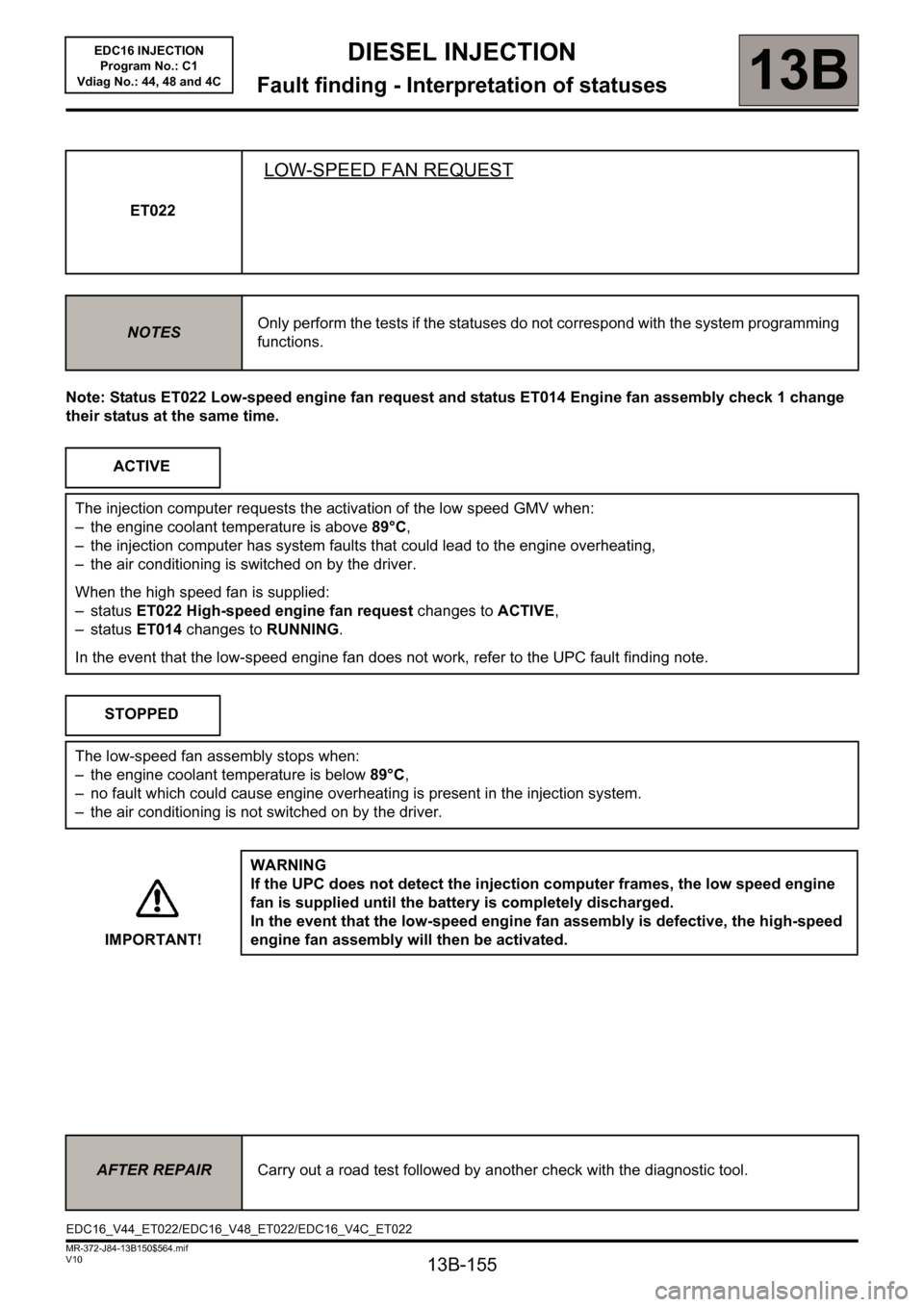
Note: Status ET022 Low-speed engine fan request and status ET014 Engine fan assembly check 1 change
their status at the same time.ET022
LOW-SPEED FAN REQUEST
NOTESOnly perform the tests if the statuses do not correspond with the system programming
functions.
ACTIVE
The injection computer requests the activation of the low speed GMV when:
– the engine coolant temperature is above 89°C,
– the injection computer has system faults that could lead to the engine overheating,
– the air conditioning is switched on by the driver.
When the high speed fan is supplied:
– status ET022 High-speed engine fan request changes to ACTIVE,
– status ET014 changes to RUNNING.
In the event that the low-speed engine fan does not work, refer to the UPC fault finding note.
STOPPED
The low-speed fan assembly stops when:
– the engine coolant temperature is below 89°C,
– no fault which could cause engine overheating is present in the injection system.
– the air conditioning is not switched on by the driver.
IMPORTANT!WARNING
If the UPC does not detect the injection computer frames, the low speed engine
fan is supplied until the battery is completely discharged.
In the event that the low-speed engine fan assembly is defective, the high-speed
engine fan assembly will then be activated.
AFTER REPAIRCarry out a road test followed by another check with the diagnostic tool.
EDC16_V44_ET022/EDC16_V48_ET022/EDC16_V4C_ET022
Page 163 of 236
13B-163
DIESEL INJECTION
Fault finding - Interpretation of statuses13B
V10 MR-372-J84-13B150$564.mif
EDC16 INJECTION
Program No.: C1
Vdiag No.: 44, 48 and 4C
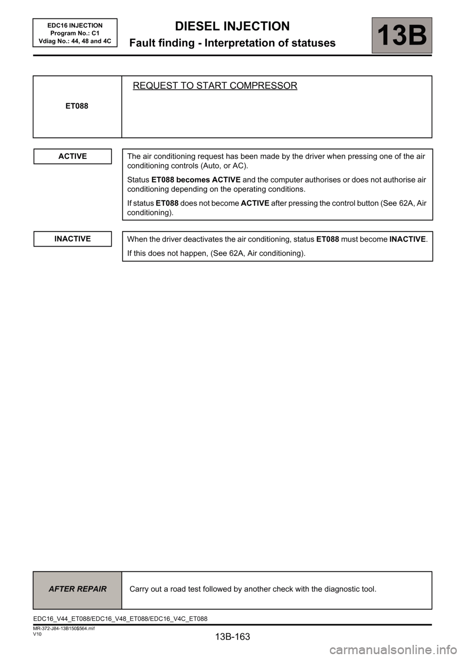
ET088
REQUEST TO START COMPRESSOR
ACTIVEThe air conditioning request has been made by the driver when pressing one of the air
conditioning controls (Auto, or AC).
Status ET088 becomes ACTIVE and the computer authorises or does not authorise air
conditioning depending on the operating conditions.
If status ET088 does not become ACTIVE after pressing the control button (See 62A, Air
conditioning).
INACTIVE
When the driver deactivates the air conditioning, status ET088 must become INACTIVE.
If this does not happen, (See 62A, Air conditioning).
AFTER REPAIRCarry out a road test followed by another check with the diagnostic tool.
EDC16_V44_ET088/EDC16_V48_ET088/EDC16_V4C_ET088
Page 180 of 236
13B - 180
DIESEL INJECTION
Fault finding - Parameter summary table13B
V10 MR-372-J84-13B150$611.mif
EDC16 INJECTION
Program No.: C1
Vdiag No.: 44, 48 and 4CDIESEL INJECTION
Fault finding - Parameter summary table
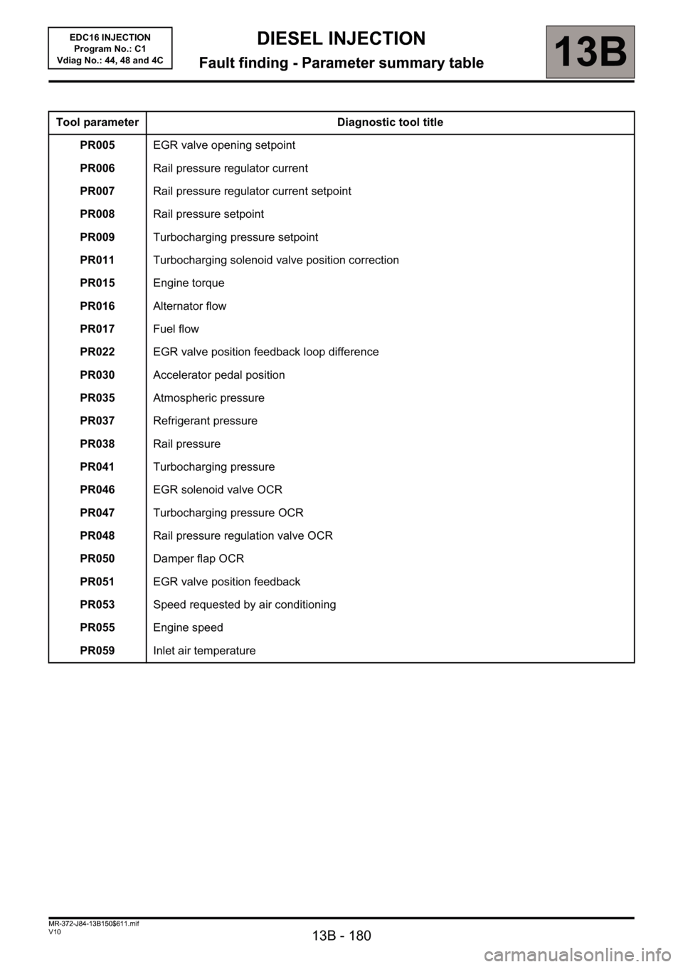
Tool parameter Diagnostic tool title
PR005EGR valve opening setpoint
PR006Rail pressure regulator current
PR007Rail pressure regulator current setpoint
PR008Rail pressure setpoint
PR009Turbocharging pressure setpoint
PR011Turbocharging solenoid valve position correction
PR015Engine torque
PR016Alternator flow
PR017Fuel flow
PR022EGR valve position feedback loop difference
PR030Accelerator pedal position
PR035Atmospheric pressure
PR037Refrigerant pressure
PR038Rail pressure
PR041Turbocharging pressure
PR046EGR solenoid valve OCR
PR047Turbocharging pressure OCR
PR048Rail pressure regulation valve OCR
PR050Damper flap OCR
PR051EGR valve position feedback
PR053Speed requested by air conditioning
PR055Engine speed
PR059Inlet air temperature
MR-372-J84-13B150$611.mif
Page 181 of 236
13B - 181
DIESEL INJECTION
Fault finding - Parameter summary table13B
V10 MR-372-J84-13B150$611.mif
EDC16 INJECTION
Program No.: C1
Vdiag No.: 44, 48 and 4C
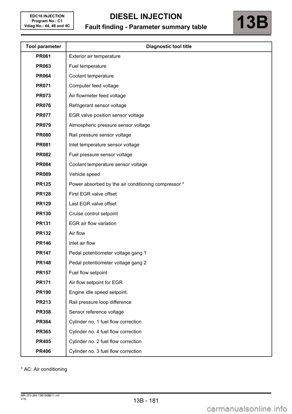
Tool parameter Diagnostic tool title
PR061Exterior air temperature
PR063Fuel temperature
PR064Coolant temperature
PR071Computer feed voltage
PR073Air flowmeter feed voltage
PR076Refrigerant sensor voltage
PR077EGR valve position sensor voltage
PR079Atmospheric pressure sensor voltage
PR080Rail pressure sensor voltage
PR081Inlet temperature sensor voltage
PR082Fuel pressure sensor voltage
PR084Coolant temperature sensor voltage
PR089Vehicle speed
PR125Power absorbed by the air conditioning compressor *
PR128First EGR valve offset
PR129Last EGR valve offset
PR130Cruise control setpoint
PR131EGR air flow variation
PR132Air flow
PR146Inlet air flow
PR147Pedal potentiometer voltage gang 1
PR148Pedal potentiometer voltage gang 2
PR157Fuel flow setpoint
PR171Air flow setpoint for EGR
PR190Engine idle speed setpoint.
PR213Rail pressure loop difference
PR358Sensor reference voltage
PR364Cylinder no. 1 fuel flow correction
PR365Cylinder no. 4 fuel flow correction
PR405Cylinder no. 2 fuel flow correction
PR406Cylinder no. 3 fuel flow correction
* AC: Air conditioning
Page 183 of 236
13B - 183
DIESEL INJECTION
Fault finding - Interpretation of parameters13B
V10 MR-372-J84-13B150$658.mif
EDC16 INJECTION
Program No.: C1
Vdiag No: 44, 48 and 4C
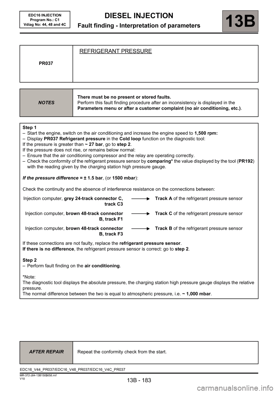
PR037
REFRIGERANT PRESSURE
NOTESThere must be no present or stored faults.
Perform this fault finding procedure after an inconsistency is displayed in the
Parameters menu or after a customer complaint (no air conditioning, etc.).
Step 1
– Start the engine, switch on the air conditioning and increase the engine speed to 1,500 rpm:
– Display PR037 Refrigerant pressure in the Cold loop function on the diagnostic tool:
If the pressure is greater than ~27bar, go to step 2.
If the pressure does not rise, or remains below normal:
– Ensure that the air conditioning compressor and the relay are operating correctly.
– Check the conformity of the refrigerant pressure sensor by comparing* the value displayed by the tool (PR192)
with the reading given by the charging station high pressure gauge.
If the pressure difference = ±1.5bar, (or 1500 mbar):
Check the continuity and the absence of interference resistance on the connections between:
Injection computer, grey 24-track connector C,
track C3Track A of the refrigerant pressure sensor
Injection computer, brown 48-track connector
B, track F1Track C of the refrigerant pressure sensor
Injection computer, brown 48-track connector
B, track F3Track B of the refrigerant pressure sensor
If these connections are not faulty, replace the refrigerant pressure sensor.
If there is no difference, the refrigerant pressure sensor is correct: go to step 2.
Step 2
– Perform fault finding on the air conditioning.
*Note:
The diagnostic tool displays the absolute pressure, the charging station high pressure gauge displays the relative
pressure.
The normal difference between the two is equal to atmospheric pressure, i.e. ~1,000mbar.
AFTER REPAIRRepeat the conformity check from the start.
EDC16_V44_PR037/EDC16_V48_PR037/EDC16_V4C_PR037
Page 189 of 236
13B - 189
DIESEL INJECTION
13B
V10 MR-372-J84-13B150$752.mif
EDC16 INJECTION
Program No.: C1
Vdiag No: 44, 48 and 4CDIESEL INJECTION
Fault finding - Interpretation of commands
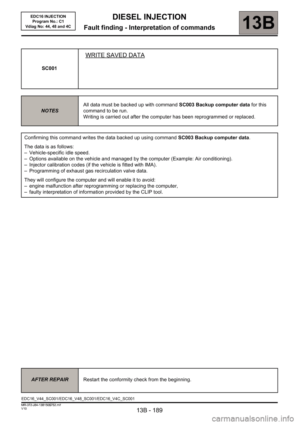
SC001
WRITE SAVED DATA
NOTESAll data must be backed up with command SC003 Backup computer data for this
command to be run.
Writing is carried out after the computer has been reprogrammed or replaced.
Confirming this command writes the data backed up using command SC003 Backup computer data.
The data is as follows:
– Vehicle-specific idle speed.
– Options available on the vehicle and managed by the computer (Example: Air conditioning).
– Injector calibration codes (if the vehicle is fitted with IMA).
– Programming of exhaust gas recirculation valve data.
They will configure the computer and will enable it to avoid:
– engine malfunction after reprogramming or replacing the computer,
– faulty interpretation of information provided by the CLIP tool.
AFTER REPAIRRestart the conformity check from the beginning.
EDC16_V44_SC001/EDC16_V48_SC001/EDC16_V4C_SC001
MR-372-J84-13B150$752.mif
Page 191 of 236
13B - 191
DIESEL INJECTION
Fault finding - Interpretation of commands13B
V10 MR-372-J84-13B150$752.mif
EDC16 INJECTION
Program No.: C1
Vdiag No: 44, 48 and 4C
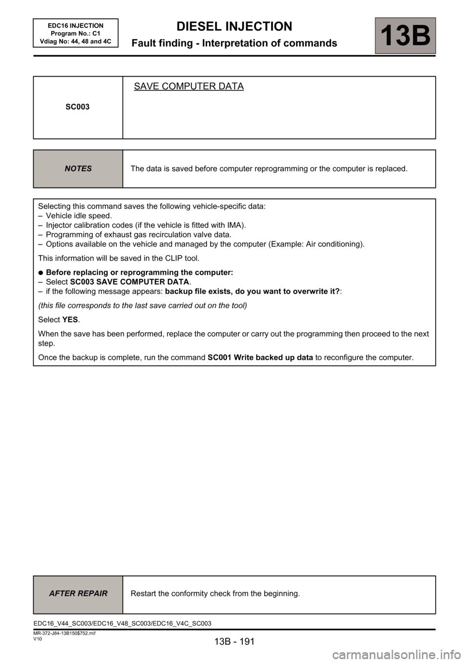
SC003
SAVE COMPUTER DATA
NOTESThe data is saved before computer reprogramming or the computer is replaced.
Selecting this command saves the following vehicle-specific data:
– Vehicle idle speed.
– Injector calibration codes (if the vehicle is fitted with IMA).
– Programming of exhaust gas recirculation valve data.
– Options available on the vehicle and managed by the computer (Example: Air conditioning).
This information will be saved in the CLIP tool.
●Before replacing or reprogramming the computer:
–Select SC003 SAVE COMPUTER DATA.
– if the following message appears: backup file exists, do you want to overwrite it?:
(this file corresponds to the last save carried out on the tool)
Select YES.
When the save has been performed, replace the computer or carry out the programming then proceed to the next
step.
Once the backup is complete, run the command SC001 Write backed up data to reconfigure the computer.
AFTER REPAIRRestart the conformity check from the beginning.
EDC16_V44_SC003/EDC16_V48_SC003/EDC16_V4C_SC003