lock RENAULT SCENIC 2011 J95 / 3.G Engine And Peripherals EDC16 Injection User Guide
[x] Cancel search | Manufacturer: RENAULT, Model Year: 2011, Model line: SCENIC, Model: RENAULT SCENIC 2011 J95 / 3.GPages: 236, PDF Size: 1.32 MB
Page 107 of 236
13B-107
DIESEL INJECTION
Fault finding - Interpretation of faults
13B
V10 MR-372-J84-13B150$376.mif
EDC16 INJECTION
Program No.: C1
Vdiag No.: 4C
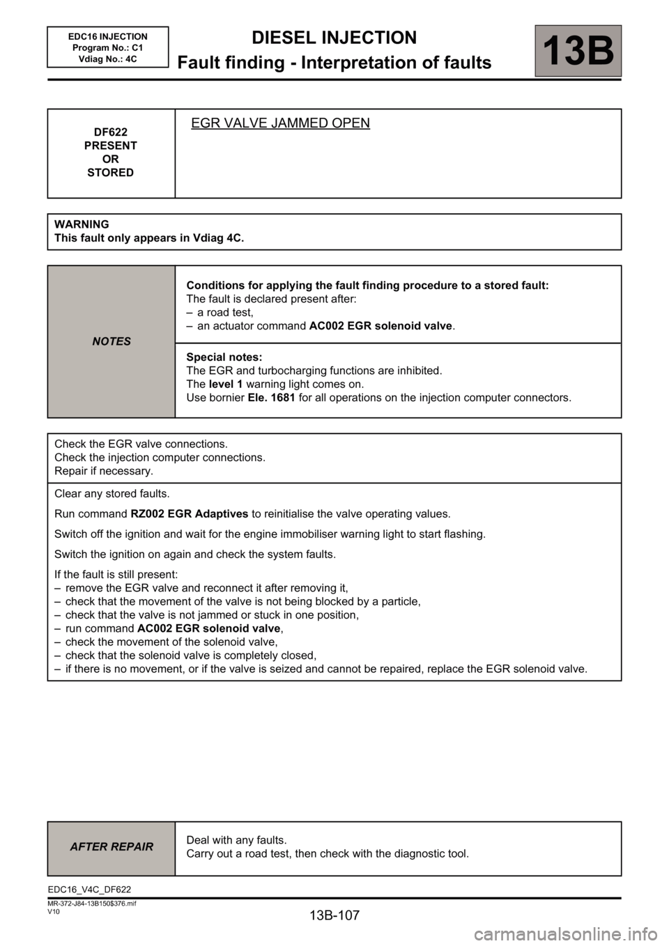
DF622
PRESENT
OR
STOREDEGR VALVE JAMMED OPEN
WARNING
This fault only appears in Vdiag 4C.
NOTESConditions for applying the fault finding procedure to a stored fault:
The fault is declared present after:
– a road test,
– an actuator command AC002 EGR solenoid valve.
Special notes:
The EGR and turbocharging functions are inhibited.
The level 1 warning light comes on.
Use bornier Ele. 1681 for all operations on the injection computer connectors.
Check the EGR valve connections.
Check the injection computer connections.
Repair if necessary.
Clear any stored faults.
Run command RZ002 EGR Adaptives to reinitialise the valve operating values.
Switch off the ignition and wait for the engine immobiliser warning light to start flashing.
Switch the ignition on again and check the system faults.
If the fault is still present:
– remove the EGR valve and reconnect it after removing it,
– check that the movement of the valve is not being blocked by a particle,
– check that the valve is not jammed or stuck in one position,
– run command AC002 EGR solenoid valve,
– check the movement of the solenoid valve,
– check that the solenoid valve is completely closed,
– if there is no movement, or if the valve is seized and cannot be repaired, replace the EGR solenoid valve.
AFTER REPAIRDeal with any faults.
Carry out a road test, then check with the diagnostic tool.
EDC16_V4C_DF622
Page 125 of 236
13B-125
DIESEL INJECTION
Fault finding - Conformity check13B
V10 MR-372-J84-13B150$423.mif
EDC16 INJECTION
Program No.: C1
Vdiag No: 44, 48 and 4C
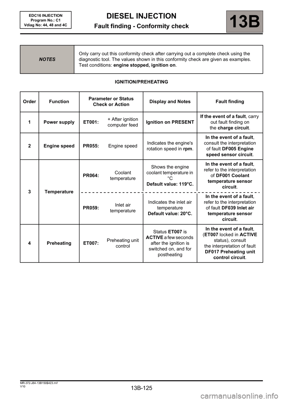
IGNITION/PREHEATING
NOTESOnly carry out this conformity check after carrying out a complete check using the
diagnostic tool. The values shown in this conformity check are given as examples.
Test conditions: engine stopped, ignition on.
Order FunctionParameter or Status
Check or ActionDisplay and Notes Fault finding
1 Power supply ET001: + After ignition
computer feedIgnition on PRESENTIf the event of a fault, carry
out fault finding on
thecharge circuit.
2 Engine speed PR055: Engine speed Indicates the engine's
rotation speed in rpm.In the event of a fault,
consult the interpretation
of fault DF005 Engine
speed sensor circuit.
3 TemperaturePR064: Coolant
temperatureShows the engine
coolant temperature in
°C
Default value: 119°C.In the event of a fault,
refer to the interpretation
ofDF001 Coolant
temperature sensor
circuit.
PR059:Inlet air
temperatureIndicates the inlet air
temperature
Default value: 20°C.In the event of a fault,
refer to the interpretation
of fault DF039 Inlet air
temperature sensor
circuit.
4 Preheating ET007: Preheating unit
controlStatus ET007 is
ACTIVE a few seconds
after the ignition is
switched on, and for
postheatingIn the event of a fault,
(ET007 locked in ACTIVE
status), consult
the interpretation of fault
DF017 Preheating unit
control circuit.
Page 127 of 236
13B-127
DIESEL INJECTION
Fault finding - Conformity check13B
V10 MR-372-J84-13B150$423.mif
EDC16 INJECTION
Program No.: C1
Vdiag No: 44, 48 and 4C
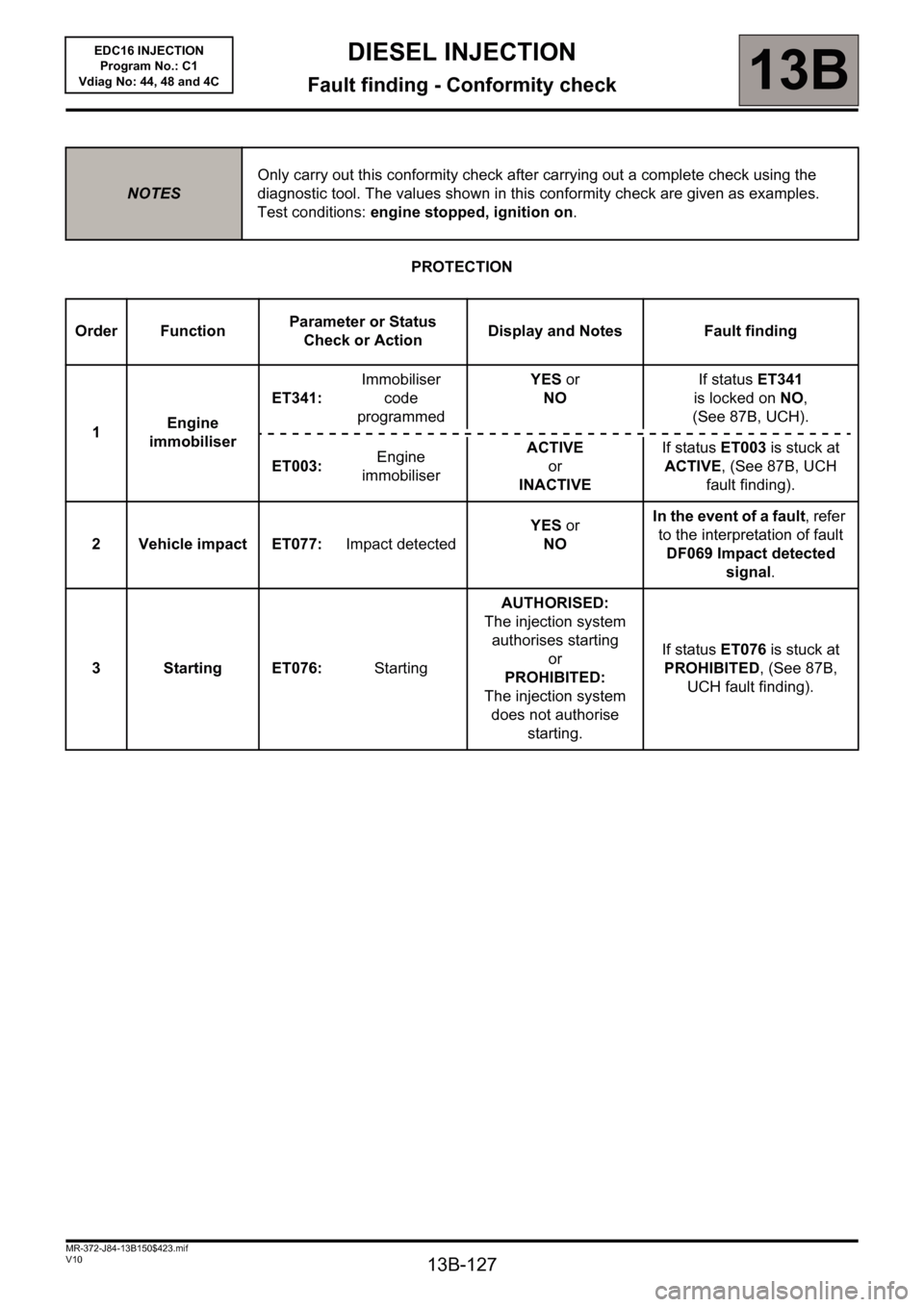
PROTECTION
NOTESOnly carry out this conformity check after carrying out a complete check using the
diagnostic tool. The values shown in this conformity check are given as examples.
Test conditions: engine stopped, ignition on.
Order FunctionParameter or Status
Check or ActionDisplay and Notes Fault finding
1Engine
immobiliserET341: Immobiliser
code
programmedYES or
NOIf status ET341
is locked on NO,
(See 87B, UCH).
ET003: Engine
immobiliserACTIVE
or
INACTIVEIf status ET003 is stuck at
ACTIVE, (See 87B, UCH
fault finding).
2 Vehicle impact ET077: Impact detectedYES or
NOIn the event of a fault, refer
to the interpretation of fault
DF069 Impact detected
signal.
3 Starting ET076: StartingAUTHORISED:
The injection system
authorises starting
or
PROHIBITED:
The injection system
does not authorise
starting.If status ET076 is stuck at
PROHIBITED, (See 87B,
UCH fault finding).
Page 144 of 236
13B - 144
DIESEL INJECTION
Fault finding - Conformity check13B
V10 MR-372-J84-13B150$470.mif
EDC16 INJECTION
Program No.: C1
Vdiag No.: 44, 48 and 4C
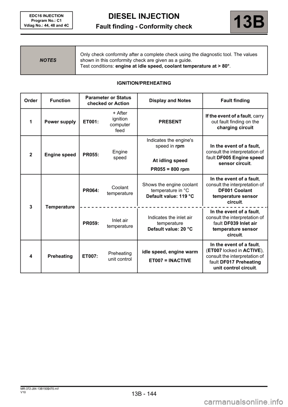
IGNITION/PREHEATING
NOTESOnly check conformity after a complete check using the diagnostic tool. The values
shown in this conformity check are given as a guide.
Test conditions: engine at idle speed, coolant temperature at > 80°.
Order FunctionParameter or Status
checked or ActionDisplay and Notes Fault finding
1 Power supply ET001:+ After
ignition
computer
feedPRESENT If the event of a fault, carry
out fault finding on the
charging circuit
2 Engine speed PR055: Engine
speedIndicates the engine's
speed in rpm
At idling speed
PR055 = 800 rpmIn the event of a fault,
consult the interpretation of
fault DF005 Engine speed
sensor circuit.
3TemperaturePR064: Coolant
temperatureShows the engine coolant
temperature in °C
Default value: 119 °CIn the event of a fault,
consult the interpretation of
DF001 Coolant
temperature sensor
circuit.
PR059:Inlet air
temperatureIndicates the inlet air
temperature
Default value: 20 °CIn the event of a fault,
consult the interpretation of
fault DF039 Inlet air
temperature sensor
circuit.
4 Preheating ET007:Preheating
unit controlidle speed, engine warm
ET007 = INACTIVEIn the event of a fault,
(ET007 locked in ACTIVE),
consult the interpretation of
fault DF017 Preheating
unit control circuit.
Page 170 of 236
13B-170
DIESEL INJECTION
Fault finding - Interpretation of statuses13B
V10 MR-372-J84-13B150$564.mif
EDC16 INJECTION
Program No.: C1
Vdiag No.: 44, 48 and 4C
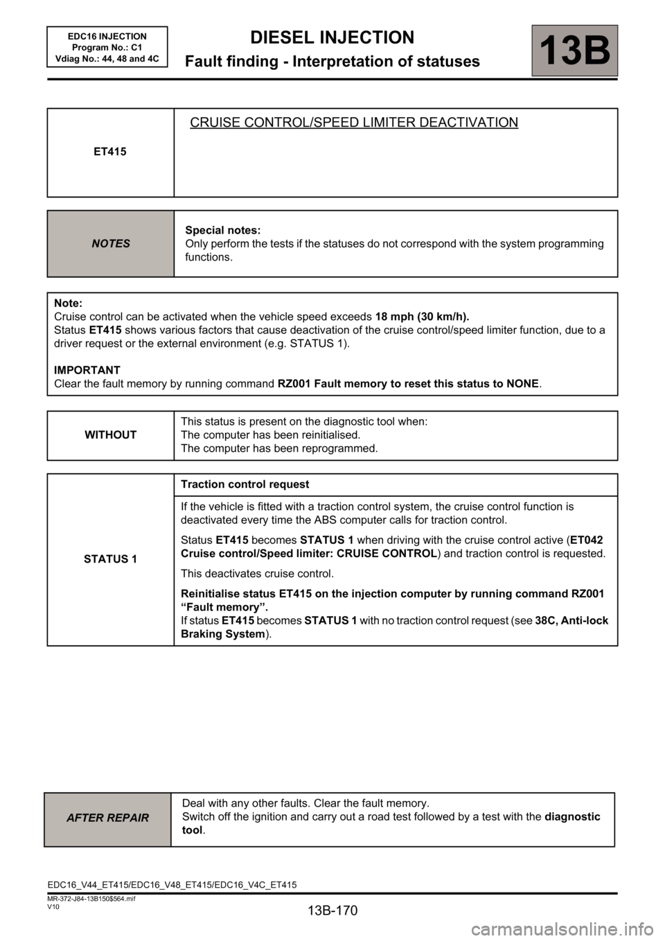
ET415
CRUISE CONTROL/SPEED LIMITER DEACTIVATION
NOTESSpecial notes:
Only perform the tests if the statuses do not correspond with the system programming
functions.
Note:
Cruise control can be activated when the vehicle speed exceeds 18 mph (30 km/h).
Status ET415 shows various factors that cause deactivation of the cruise control/speed limiter function, due to a
driver request or the external environment (e.g. STATUS 1).
IMPORTANT
Clear the fault memory by running command RZ001 Fault memory to reset this status to NONE.
WITHOUTThis status is present on the diagnostic tool when:
The computer has been reinitialised.
The computer has been reprogrammed.
STATUS 1Traction control request
If the vehicle is fitted with a traction control system, the cruise control function is
deactivated every time the ABS computer calls for traction control.
Status ET415 becomes STATUS 1 when driving with the cruise control active (ET042
Cruise control/Speed limiter: CRUISE CONTROL) and traction control is requested.
This deactivates cruise control.
Reinitialise status ET415 on the injection computer by running command RZ001
“Fault memory”.
If status ET415 becomes STATUS 1 with no traction control request (see 38C, Anti-lock
Braking System).
AFTER REPAIRDeal with any other faults. Clear the fault memory.
Switch off the ignition and carry out a road test followed by a test with the diagnostic
tool.
EDC16_V44_ET415/EDC16_V48_ET415/EDC16_V4C_ET415
Page 174 of 236
13B-174
DIESEL INJECTION
Fault finding - Interpretation of statuses13B
V10 MR-372-J84-13B150$564.mif
EDC16 INJECTION
Program No.: C1
Vdiag No.: 44, 48 and 4C
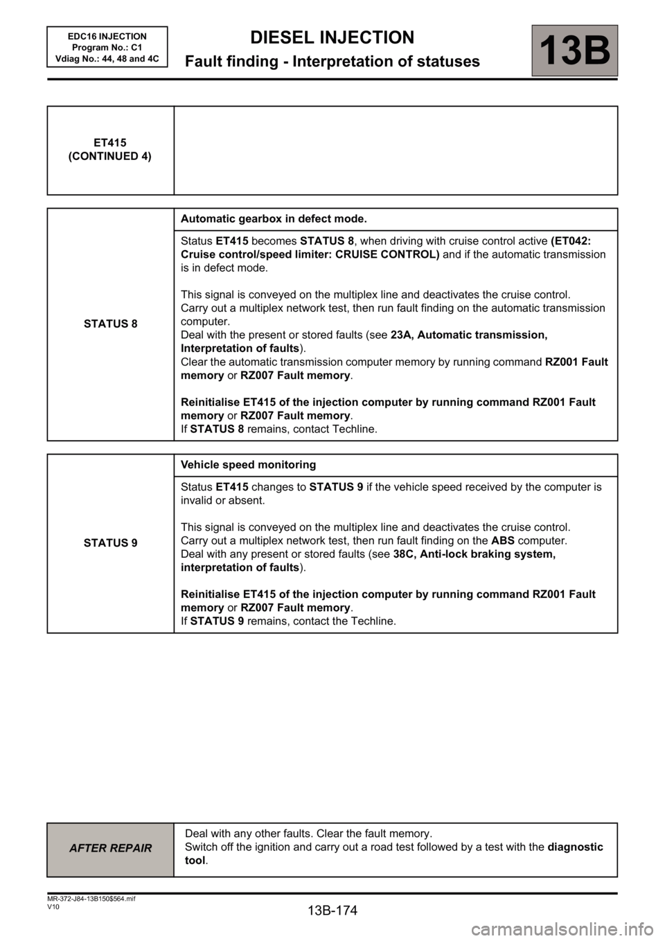
ET415
(CONTINUED 4)
STATUS 8Automatic gearbox in defect mode.
Status ET415 becomes STATUS 8, when driving with cruise control active (ET042:
Cruise control/speed limiter: CRUISE CONTROL) and if the automatic transmission
is in defect mode.
This signal is conveyed on the multiplex line and deactivates the cruise control.
Carry out a multiplex network test, then run fault finding on the automatic transmission
computer.
Deal with the present or stored faults (see 23A, Automatic transmission,
Interpretation of faults).
Clear the automatic transmission computer memory by running command RZ001 Fault
memory or RZ007 Fault memory.
Reinitialise ET415 of the injection computer by running command RZ001 Fault
memory or RZ007 Fault memory.
If STATUS 8 remains, contact Techline.
STATUS 9Vehicle speed monitoring
Status ET415 changes to STATUS 9 if the vehicle speed received by the computer is
invalid or absent.
This signal is conveyed on the multiplex line and deactivates the cruise control.
Carry out a multiplex network test, then run fault finding on the ABS computer.
Deal with any present or stored faults (see 38C, Anti-lock braking system,
interpretation of faults).
Reinitialise ET415 of the injection computer by running command RZ001 Fault
memory or RZ007 Fault memory.
If STATUS 9 remains, contact the Techline.
AFTER REPAIRDeal with any other faults. Clear the fault memory.
Switch off the ignition and carry out a road test followed by a test with the diagnostic
tool.
Page 195 of 236
13B - 195
DIESEL INJECTION
Fault finding - Interpretation of commands13B
V10 MR-372-J84-13B150$752.mif
EDC16 INJECTION
Program No.: C1
Vdiag No: 44, 48 and 4C
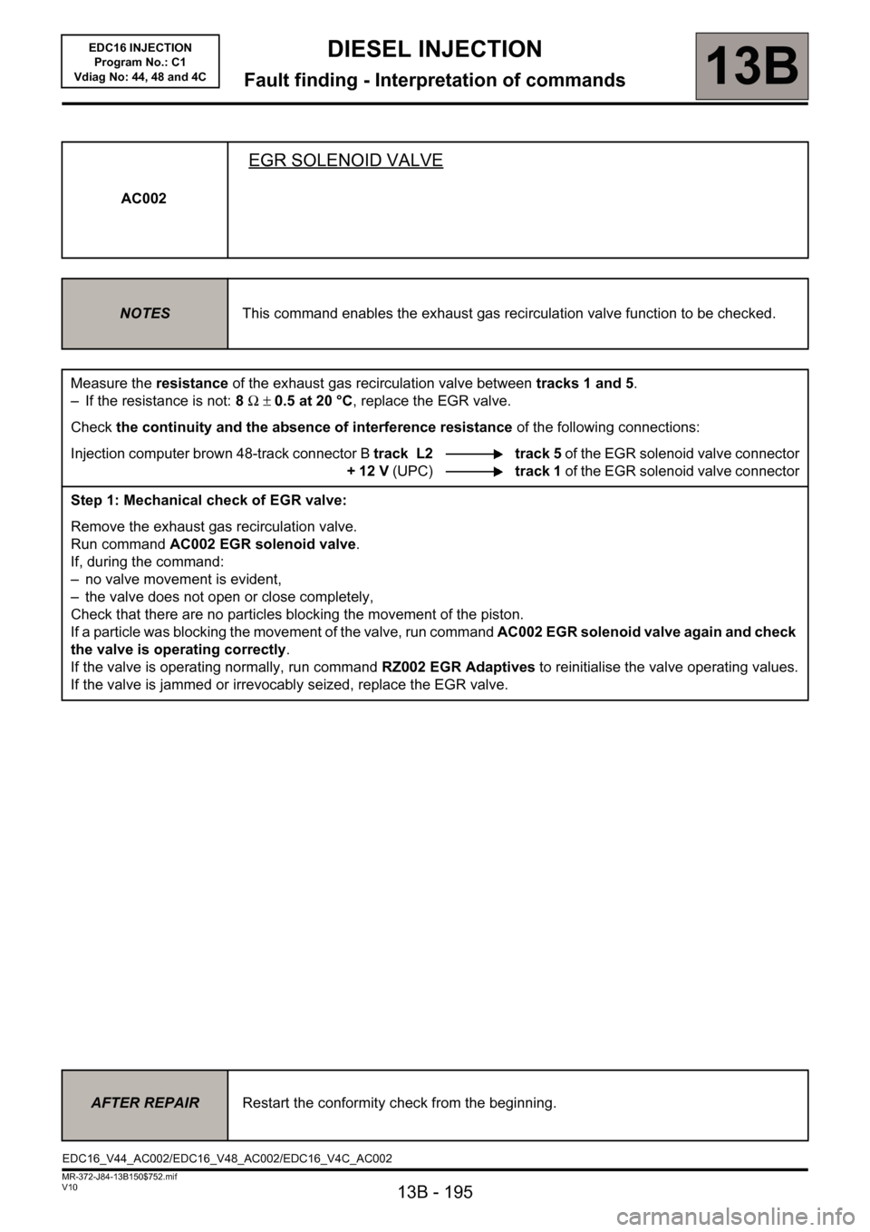
AC002
EGR SOLENOID VALVE
NOTESThis command enables the exhaust gas recirculation valve function to be checked.
Measure the resistance of the exhaust gas recirculation valve between tracks 1 and 5.
– If the resistance is not: 8 Ω ± 0.5 at 20 °C, replace the EGR valve.
Check the continuity and the absence of interference resistance of the following connections:
Injection computer brown 48-track connector B track L2 track 5 of the EGR solenoid valve connector
+ 12 V (UPC)track 1 of the EGR solenoid valve connector
Step 1: Mechanical check of EGR valve:
Remove the exhaust gas recirculation valve.
Run command AC002 EGR solenoid valve.
If, during the command:
– no valve movement is evident,
– the valve does not open or close completely,
Check that there are no particles blocking the movement of the piston.
If a particle was blocking the movement of the valve, run command AC002 EGR solenoid valve again and check
the valve is operating correctly.
If the valve is operating normally, run command RZ002 EGR Adaptives to reinitialise the valve operating values.
If the valve is jammed or irrevocably seized, replace the EGR valve.
AFTER REPAIRRestart the conformity check from the beginning.
EDC16_V44_AC002/EDC16_V48_AC002/EDC16_V4C_AC002
Page 197 of 236
13B - 197
DIESEL INJECTION
Fault finding - Interpretation of commands13B
V10 MR-372-J84-13B150$752.mif
EDC16 INJECTION
Program No.: C1
Vdiag No: 44, 48 and 4C
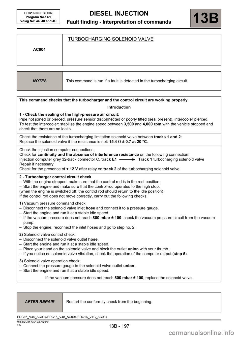
AC004
TURBOCHARGING SOLENOID VALVE
NOTESThis command is run if a fault is detected in the turbocharging circuit.
This command checks that the turbocharger and the control circuit are working properly.
Introduction
1 - Check the sealing of the high-pressure air circuit:
Pipe not joined or pierced, pressure sensor disconnected or poorly fitted (seal present), intercooler pierced.
To test the intercooler: stabilise the engine speed between 3,500 and 4,000 rpm with the vehicle stopped and
check that there are no leaks.
Check the resistance of the turbocharging limitation solenoid valve between tracks 1 and 2:
Replace the solenoid valve if the resistance is not: 15.4 Ω ± 0.7 at 20 °C.
Check the injection computer connections.
Check for continuity and the absence of interference resistance on the following connection:
Injection computer grey 32-track connector C, track E1 Track 1 turbocharging solenoid valve
Repair if necessary.
Check for the presence of +12V after relay on track 2 of the turbocharging solenoid valve.
2 - Turbocharger control circuit check
– With the engine stopped, make sure that the control rod is in the rest position.
– Start the engine and make sure that the control rod operates to the high stop.
(when the engine is switched off, the control rod should return to the idle position)
If the control rod does not move correctly, carry out the following checks:
1) Vacuum pressure command check:
– Disconnect the solenoid valve inlet hose and connect it to a pressure gauge.
– Start the engine and run it at a stable idle speed.
– If the vacuum pressure does not reach 800 mbar ± 100: check the vacuum pressure circuit from the vacuum
pump.
– Stop the engine, reconnect the inlet hoses and go to step no. 2.
2) Solenoid valve control check:
– Disconnect the solenoid valve outlet hose.
– Start the engine and run it at a stable idle speed.
– Place your hand on the solenoid valve and block the outlet union with your thumb.
– If you notice no solenoid valve vibration, check the operation of the computer output (step 5).
3) Solenoid valve operation check:
– Connect the pressure gauge to the solenoid valve outlet union.
– Start the engine and run it at a stable idle speed.
If the vacuum pressure does not reach 800 mbar ± 100, replace the solenoid valve.
AFTER REPAIRRestart the conformity check from the beginning.
EDC16_V44_AC004/EDC16_V48_AC004/EDC16_V4C_AC004
Page 198 of 236
13B - 198
DIESEL INJECTION
Fault finding - Interpretation of commands13B
V10 MR-372-J84-13B150$752.mif
EDC16 INJECTION
Program No.: C1
Vdiag No: 44, 48 and 4C
* Opening Cyclic Ratio. AC004
CONTINUED
Turbocharger control circuit check (continued)
4) Turbocharging operation check:
a) Connect vacuum pump to the hoses connected to the turbocharger control diaphragm,
– Apply a vacuum pressure of 800 mbar:
If there is a leak, replace the turbocharger (diaphragm included).
b) Check the movement of the control rod (See MR 364, 12B, Mechanical, Turbocharging).
If the control rod is sticking, replace the turbocharger.
c) Engine cold and switched off:
– Remove the turbocharger inlet duct and check that the compressor turns freely on the axis.
d) If the fault is still present:
– Check that the exhaust manifold is not leaking.
– Check that the exhaust is not blocked.
Carry out the necessary repairs.
5) Computer output check (solenoid valve connected):
This operation can only be carried out if the checks indicated in step no. 2 are not conclusive.
Using a voltmeter:
– Connect the voltmeter earth to track 2 of the solenoid valve and the positive cable to track 1.
– Clear any solenoid valve fault then run command AC004:
The voltmeter should display ten cycles of two successive voltages ~ =battery voltage X OCR* current.
either: ~2.5V (OCR for 20 %) then ~8.7V (OCR for 70 %).
Or using an oscilloscope (range 5 V/division and with time base 1 ms/division):
– Connect the earth of the oscilloscope to the battery earth and the positive test pin to track 2 of the solenoid valve.
– Clear any solenoid valve faults, then run command AC004:
the oscilloscope should display a square wave signal of 12.5 V in amplitude at a frequency of 140 Hz
(with an OCR alternating from ~ 20 to ~ 70 %).
– If the measurement is correct, replace the solenoid valve.
– If the measurement does not show any control or continuous voltage, contact the Techline.
AFTER REPAIRRestart the conformity check from the beginning.
Page 201 of 236
13B - 201
DIESEL INJECTION
Fault finding - Interpretation of commands13B
V10 MR-372-J84-13B150$752.mif
EDC16 INJECTION
Program No.: C1
Vdiag No: 44, 48 and 4C
AC014
DAMPER FLAP
NOTESThis command enables the damper flap function to be checked.
– Measure the resistance of the inlet flap valve solenoid valve between tracks 1 and 2.
Replace the solenoid valve if the resistance is not 46 Ω ± 3 at +25 °C.
–Check the continuity and the absence of interference resistance on the following connections:
Injection computer brown 48-track connector B track J4 Track 1 of damper flap solenoid valve
connector
+ 12 V (UPC)Track 2 damper flap solenoid valve
connector
A) Engine running at idle speed:
– Make sure that there is a vacuum pressure of: ~ 900 mb in the solenoid valve inlet hose.
Make the necessary repairs (vacuum pressure circuit conformity and seal).
B) With the vehicle ignition on, engine stopped:
– Check that the inlet flap is open.
If not, clean or replace the air vent unit.
– Disconnect the solenoid valve inlet and outlet hoses.
– Connect a vacuum pump to the inlet union and apply a vacuum pressure of ~ 900 mbar.
If there is a leak, replace the solenoid valve.
– Run command AC014.
– If the solenoid valve opens (vacuum pump pressure gauge returns to atmospheric pressure), go to step C.
– Otherwise, with the solenoid valve connected, check operation of the computer output with a voltmeter:
Voltmeter earth cabletrack 1 of the solenoid valve
Voltmeter positive leadtrack 2 of the solenoid valve
Clear any solenoid valve faults,
Run command AC014.
The voltmeter should display ten ON-OFF cycles (8.75 V then 2.5 V).
If the measurement is correct, replace the solenoid valve.
If the measurement shows is not controlled, contact the Techline.
C) Vehicle with ignition off:
– Connect a vacuum pump to the flap control diaphragm and apply a vacuum pressure of ~ 900 mbar:
– If the diaphragm does not maintain the vacuum pressure, replace the air vent unit (the diaphragm cannot be
disconnected).
– If the diaphragm maintains the vacuum pressure and the valve does not operate, clean or replace the air
vent unit.
– If the diaphragm maintains the vacuum pressure and the flap operates then operate it several times to ensure
that there is no blockage.
Check for clogging of the air vent unit and the valve, and clean if necessary.
AFTER REPAIRRepeat the conformity check from the start.
EDC16_V44_AC014/EDC16_V48_AC014/EDC16_V4C_AC014