coolant temperature RENAULT SCENIC 2011 J95 / 3.G Engine And Peripherals EDC16 Injection Owner's Guide
[x] Cancel search | Manufacturer: RENAULT, Model Year: 2011, Model line: SCENIC, Model: RENAULT SCENIC 2011 J95 / 3.GPages: 236, PDF Size: 1.32 MB
Page 142 of 236
13B - 142
DIESEL INJECTION
Fault finding - Conformity check13B
V10 MR-372-J84-13B150$470.mif
EDC16 INJECTION
Program No.: C1
Vdiag No.: 44, 48 and 4C
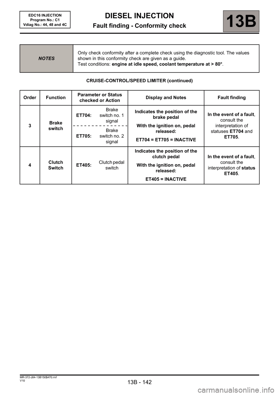
CRUISE-CONTROL/SPEED LIMITER (continued)
NOTESOnly check conformity after a complete check using the diagnostic tool. The values
shown in this conformity check are given as a guide.
Test conditions: engine at idle speed, coolant temperature at > 80°.
Order FunctionParameter or Status
checked or ActionDisplay and Notes Fault finding
3Brake
switchET704:Brake
switch no. 1
signalIndicates the position of the
brake pedal
With the ignition on, pedal
released:
ET704 = ET705 = INACTIVEIn the event of a fault,
consult the
interpretation of
statuses ET704 and
ET705. ET705:Brake
switch no. 2
signal
4Clutch
SwitchET405:Clutch pedal
switchIndicates the position of the
clutch pedal
With the ignition on, pedal
released:
ET405 = INACTIVEIn the event of a fault,
consult the
interpretation of status
ET405.
Page 143 of 236
13B - 143
DIESEL INJECTION
Fault finding - Conformity check13B
V10 MR-372-J84-13B150$470.mif
EDC16 INJECTION
Program No.: C1
Vdiag No.: 44, 48 and 4C
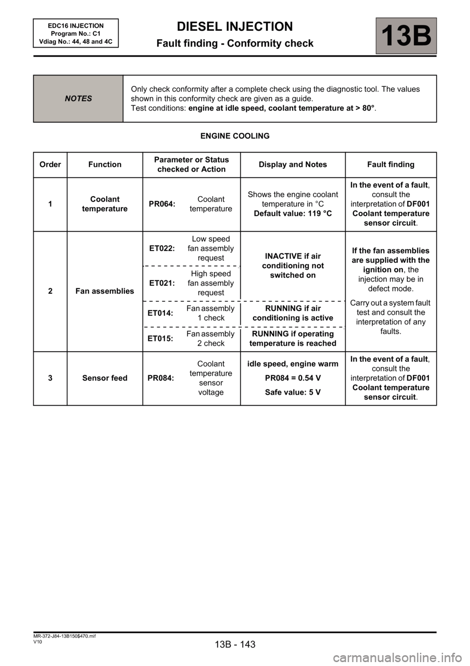
ENGINE COOLING
NOTESOnly check conformity after a complete check using the diagnostic tool. The values
shown in this conformity check are given as a guide.
Test conditions: engine at idle speed, coolant temperature at > 80°.
Order FunctionParameter or Status
checked or ActionDisplay and Notes Fault finding
1Coolant
temperaturePR064:Coolant
temperatureShows the engine coolant
temperature in °C
Default value: 119 °CIn the event of a fault,
consult the
interpretation of DF001
Coolant temperature
sensor circuit.
2 Fan assembliesET022:Low speed
fan assembly
requestINACTIVE if air
conditioning not
switched onIf the fan assemblies
are supplied with the
ignition on, the
injection may be in
defect mode.
Carry out a system fault
test and consult the
interpretation of any
faults. ET021:High speed
fan assembly
request
ET014:Fan assembly
1 checkRUNNING if air
conditioning is active
ET015:Fan assembly
2 checkRUNNING if operating
temperature is reached
3 Sensor feed PR084:Coolant
temperature
sensor
voltageidle speed, engine warm
PR084 = 0.54 V
Safe value: 5 VIn the event of a fault,
consult the
interpretation of DF001
Coolant temperature
sensor circuit.
Page 144 of 236
13B - 144
DIESEL INJECTION
Fault finding - Conformity check13B
V10 MR-372-J84-13B150$470.mif
EDC16 INJECTION
Program No.: C1
Vdiag No.: 44, 48 and 4C
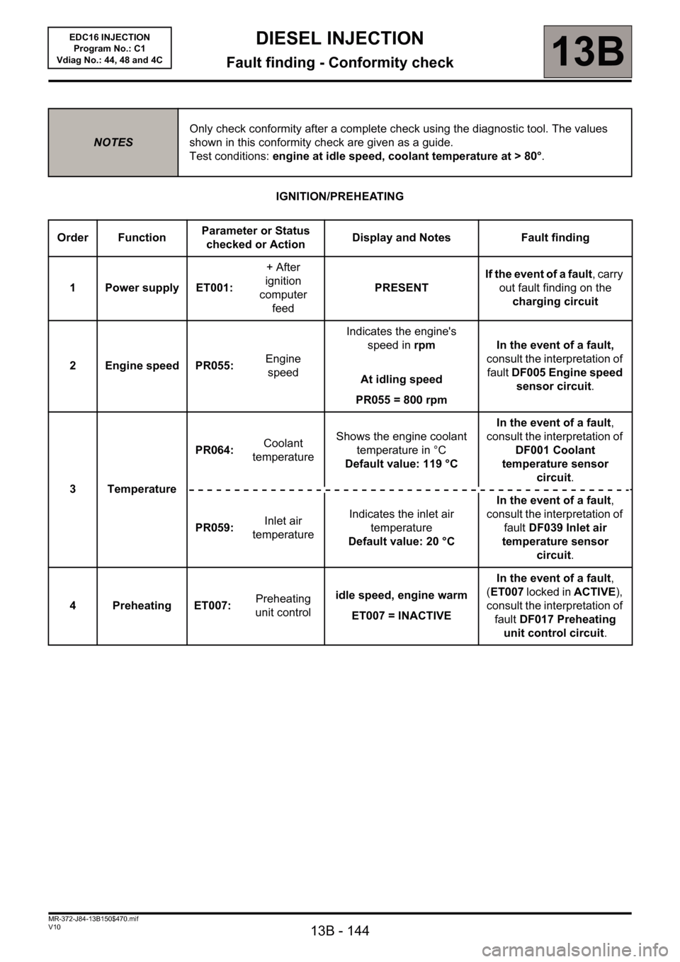
IGNITION/PREHEATING
NOTESOnly check conformity after a complete check using the diagnostic tool. The values
shown in this conformity check are given as a guide.
Test conditions: engine at idle speed, coolant temperature at > 80°.
Order FunctionParameter or Status
checked or ActionDisplay and Notes Fault finding
1 Power supply ET001:+ After
ignition
computer
feedPRESENT If the event of a fault, carry
out fault finding on the
charging circuit
2 Engine speed PR055: Engine
speedIndicates the engine's
speed in rpm
At idling speed
PR055 = 800 rpmIn the event of a fault,
consult the interpretation of
fault DF005 Engine speed
sensor circuit.
3TemperaturePR064: Coolant
temperatureShows the engine coolant
temperature in °C
Default value: 119 °CIn the event of a fault,
consult the interpretation of
DF001 Coolant
temperature sensor
circuit.
PR059:Inlet air
temperatureIndicates the inlet air
temperature
Default value: 20 °CIn the event of a fault,
consult the interpretation of
fault DF039 Inlet air
temperature sensor
circuit.
4 Preheating ET007:Preheating
unit controlidle speed, engine warm
ET007 = INACTIVEIn the event of a fault,
(ET007 locked in ACTIVE),
consult the interpretation of
fault DF017 Preheating
unit control circuit.
Page 145 of 236

13B - 145
DIESEL INJECTION
Fault finding - Conformity check13B
V10 MR-372-J84-13B150$470.mif
EDC16 INJECTION
Program No.: C1
Vdiag No.: 44, 48 and 4C
STARTING
NOTESOnly check conformity after a complete check using the diagnostic tool. The values
shown in this conformity check are given as a guide.
Test conditions: engine at idle speed, coolant temperature at > 80°.
Order FunctionParameter or Status
checked or ActionDisplay and Notes Fault finding
1 Power supplyET001: + After ignition
computer feedPRESENTIf the event of a fault,
carry out fault finding on
the charging circuit
PR071: Computer feed
voltage9 V < X < 16 VIn the event of a fault,
carry out fault finding on
the charging circuit.
PR358: Sensor
reference
voltage3.47 < X < 3.75 V
(Average of the three
sensor feed voltages)In the event of a fault,
consult the interpretation
of faults DF011 Sensor
feed voltage no. 1, DF012
Sensor feed voltage no. 2,
and DF013 Sensor feed
voltage no. 3.
2 Starting ET076:StartingAUTHORISED:
The injection gives
authorisation to start
or
PROHIBITED:
The injection does not
give authorisation to
start.If status ET076 is
PROHIBITED, carry out
fault finding on the entire
multiplex network.
3 Engine operation ET038:EngineAt idling speed
RunningNone
4 Synchronisation ET238: SynchronisationPERFORMEDIn the event of a fault,
consult the interpretation
of status ET238
Page 146 of 236
13B - 146
DIESEL INJECTION
Fault finding - Conformity check13B
V10 MR-372-J84-13B150$470.mif
EDC16 INJECTION
Program No.: C1
Vdiag No.: 44, 48 and 4C
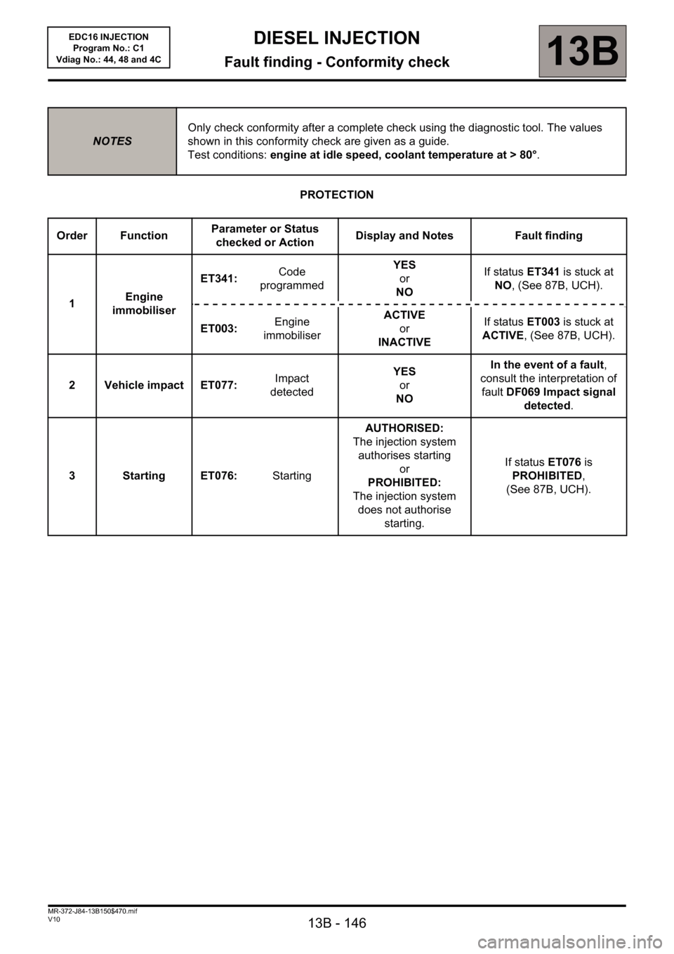
PROTECTION
NOTESOnly check conformity after a complete check using the diagnostic tool. The values
shown in this conformity check are given as a guide.
Test conditions: engine at idle speed, coolant temperature at > 80°.
Order FunctionParameter or Status
checked or ActionDisplay and Notes Fault finding
1Engine
immobiliserET341: Code
programmedYES
or
NOIf status ET341 is stuck at
NO, (See 87B, UCH).
ET003: Engine
immobiliserACTIVE
or
INACTIVEIf status ET003 is stuck at
ACTIVE, (See 87B, UCH).
2 Vehicle impact ET077: Impact
detectedYES
or
NOIn the event of a fault,
consult the interpretation of
fault DF069 Impact signal
detected.
3 Starting ET076: StartingAUTHORISED:
The injection system
authorises starting
or
PROHIBITED:
The injection system
does not authorise
starting.If status ET076 is
PROHIBITED,
(See 87B, UCH).
Page 152 of 236

13B-152
DIESEL INJECTION
Fault finding - Interpretation of statuses13B
V10 MR-372-J84-13B150$564.mif
EDC16 INJECTION
Program No.: C1
Vdiag No.: 44, 48 and 4C
ET014
FAN ASSEMBLY 1 CHECK
NOTESOnly perform the tests if the statuses do not correspond with the system programming
functions.
Note: Status ET022 Low-speed engine fan request and status ET014 Engine fan assembly check 1 change
their status at the same time.
RUNNING
The low-speed fan assembly is supplied in three scenarios:
– the engine coolant temperature is above 89°C,
– the air conditioning is operating,
– the injection computer has system faults that could lead to the engine overheating.
When the low-speed fan assembly is supplied:
– status ET014 changes to RUNNING
– status ET022 low-speed engine fan request changes to ACTIVE.
In the event that the low-speed engine fan does not work, refer to the UPC fault finding note.
STOPPED
The low-speed fan assembly stops when:
– the engine coolant temperature is below 89°C,
– no air conditioning request made by the driver.
IMPORTANT!WARNING
If the UPC does not detect the injection computer frames, the low-speed engine
fan assembly is supplied until the battery is completely discharged.
In the event that the low-speed engine fan assembly is defective, the high-speed
engine fan assembly will then be activated.
AFTER REPAIRCarry out a road test followed by another check with the diagnostic tool.
EDC16_V44_ET014/EDC16_V48_ET014/EDC16_V4C_ET014
Page 153 of 236
13B-153
DIESEL INJECTION
Fault finding - Interpretation of statuses13B
V10 MR-372-J84-13B150$564.mif
EDC16 INJECTION
Program No.: C1
Vdiag No.: 44, 48 and 4C
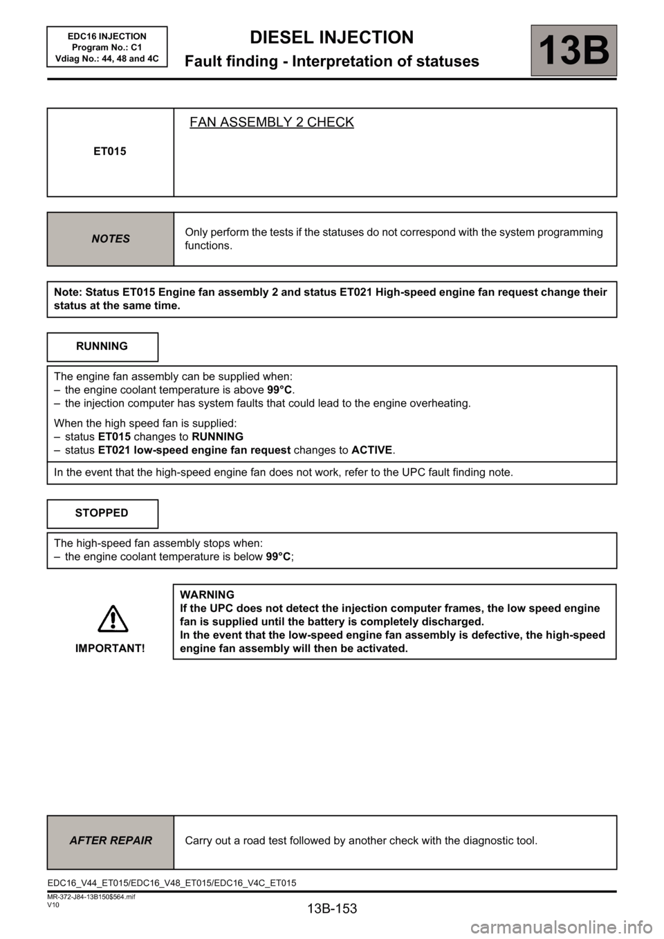
ET015
FAN ASSEMBLY 2 CHECK
NOTESOnly perform the tests if the statuses do not correspond with the system programming
functions.
Note: Status ET015 Engine fan assembly 2 and status ET021 High-speed engine fan request change their
status at the same time.
RUNNING
The engine fan assembly can be supplied when:
– the engine coolant temperature is above 99°C.
– the injection computer has system faults that could lead to the engine overheating.
When the high speed fan is supplied:
– status ET015 changes to RUNNING
– status ET021 low-speed engine fan request changes to ACTIVE.
In the event that the high-speed engine fan does not work, refer to the UPC fault finding note.
STOPPED
The high-speed fan assembly stops when:
– the engine coolant temperature is below 99°C;
IMPORTANT!WARNING
If the UPC does not detect the injection computer frames, the low speed engine
fan is supplied until the battery is completely discharged.
In the event that the low-speed engine fan assembly is defective, the high-speed
engine fan assembly will then be activated.
AFTER REPAIRCarry out a road test followed by another check with the diagnostic tool.
EDC16_V44_ET015/EDC16_V48_ET015/EDC16_V4C_ET015
Page 154 of 236
13B-154
DIESEL INJECTION
Fault finding - Interpretation of statuses13B
V10 MR-372-J84-13B150$564.mif
EDC16 INJECTION
Program No.: C1
Vdiag No.: 44, 48 and 4C
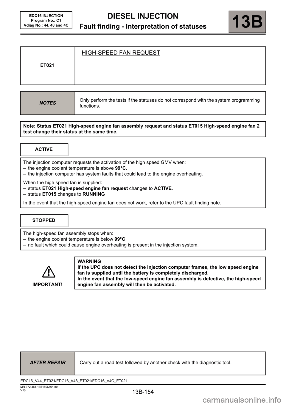
ET021
HIGH-SPEED FAN REQUEST
NOTESOnly perform the tests if the statuses do not correspond with the system programming
functions.
Note: Status ET021 High-speed engine fan assembly request and status ET015 High-speed engine fan 2
test change their status at the same time.
ACTIVE
The injection computer requests the activation of the high speed GMV when:
– the engine coolant temperature is above 99°C.
– the injection computer has system faults that could lead to the engine overheating.
When the high speed fan is supplied:
– status ET021 High-speed engine fan request changes to ACTIVE.
– status ET015 changes to RUNNING
In the event that the high-speed engine fan does not work, refer to the UPC fault finding note.
STOPPED
The high-speed fan assembly stops when:
– the engine coolant temperature is below 99°C;
– no fault which could cause engine overheating is present in the injection system.
IMPORTANT!WARNING
If the UPC does not detect the injection computer frames, the low speed engine
fan is supplied until the battery is completely discharged.
In the event that the low-speed engine fan assembly is defective, the high-speed
engine fan assembly will then be activated.
AFTER REPAIRCarry out a road test followed by another check with the diagnostic tool.
EDC16_V44_ET021/EDC16_V48_ET021/EDC16_V4C_ET021
Page 155 of 236
13B-155
DIESEL INJECTION
Fault finding - Interpretation of statuses13B
V10 MR-372-J84-13B150$564.mif
EDC16 INJECTION
Program No.: C1
Vdiag No.: 44, 48 and 4C
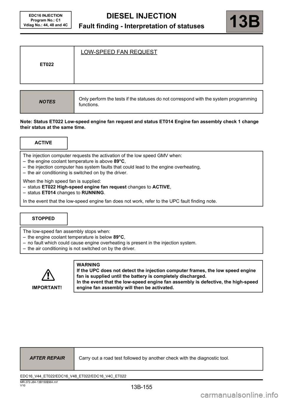
Note: Status ET022 Low-speed engine fan request and status ET014 Engine fan assembly check 1 change
their status at the same time.ET022
LOW-SPEED FAN REQUEST
NOTESOnly perform the tests if the statuses do not correspond with the system programming
functions.
ACTIVE
The injection computer requests the activation of the low speed GMV when:
– the engine coolant temperature is above 89°C,
– the injection computer has system faults that could lead to the engine overheating,
– the air conditioning is switched on by the driver.
When the high speed fan is supplied:
– status ET022 High-speed engine fan request changes to ACTIVE,
– status ET014 changes to RUNNING.
In the event that the low-speed engine fan does not work, refer to the UPC fault finding note.
STOPPED
The low-speed fan assembly stops when:
– the engine coolant temperature is below 89°C,
– no fault which could cause engine overheating is present in the injection system.
– the air conditioning is not switched on by the driver.
IMPORTANT!WARNING
If the UPC does not detect the injection computer frames, the low speed engine
fan is supplied until the battery is completely discharged.
In the event that the low-speed engine fan assembly is defective, the high-speed
engine fan assembly will then be activated.
AFTER REPAIRCarry out a road test followed by another check with the diagnostic tool.
EDC16_V44_ET022/EDC16_V48_ET022/EDC16_V4C_ET022
Page 168 of 236
13B-168
DIESEL INJECTION
Fault finding - Interpretation of statuses13B
V10 MR-372-J84-13B150$564.mif
EDC16 INJECTION
Program No.: C1
Vdiag No.: 44, 48 and 4C
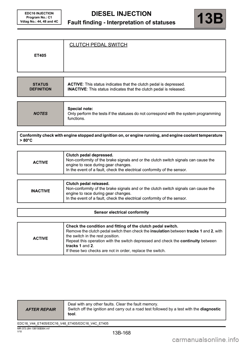
ET405
CLUTCH PEDAL SWITCH
STATUS
DEFINITIONACTIVE: This status indicates that the clutch pedal is depressed.
INACTIVE: This status indicates that the clutch pedal is released.
NOTESSpecial note:
Only perform the tests if the statuses do not correspond with the system programming
functions.
Conformity check with engine stopped and ignition on, or engine running, and engine coolant temperature
> 80°C
ACTIVEClutch pedal depressed.
Non-conformity of the brake signals and or the clutch switch signals can cause the
engine to race during gear changes.
In the event of a fault, check the electrical conformity of the sensor.
INACTIVEClutch pedal released.
Non-conformity of the brake signals and or the clutch switch signals can cause the
engine to race during gear changes.
In the event of a fault, check the electrical conformity of the sensor.
Sensor electrical conformity
ACTIVECheck the condition and fitting of the clutch pedal switch.
Remove the clutch pedal switch then check the insulation between tracks 1 and 2, with
the switch in the rest position.
Repeat this operation with the switch depressed and check the continuity between
tracks 1 and 2.
If these two checks are not in order, replace the switch.
AFTER REPAIRDeal with any other faults. Clear the fault memory.
Switch off the ignition and carry out a road test followed by a test with the diagnostic
tool.
ET405
CLUTCH PEDAL SWITCH
STATUS
DEFINITIONACTIVE: This status indicates that the clutch pedal is depressed.
INACTIVE: This status indicates that the clutch pedal is released.
NOTESSpecial note:
Only perform the tests if the statuses do not correspond with the system programming
functions.
Conformity check with engine stopped and ignition on, or engine running, and engine coolant temperature
> 80°C
ACTIVEClutch pedal depressed.
Non-conformity of the brake signals and or the clutch switch signals can cause the
engine to race during gear changes.
In the event of a fault, check the electrical conformity of the sensor.
INACTIVEClutch pedal released.
Non-conformity of the brake signals and or the clutch switch signals can cause the
engine to race during gear changes.
In the event of a fault, check the electrical conformity of the sensor.
Sensor electrical conformity
EDC16_V44_ET405/EDC16_V48_ET405/EDC16_V4C_ET405