display RENAULT SCENIC 2011 J95 / 3.G Engine And Peripherals EDC16 Injection Manual PDF
[x] Cancel search | Manufacturer: RENAULT, Model Year: 2011, Model line: SCENIC, Model: RENAULT SCENIC 2011 J95 / 3.GPages: 236, PDF Size: 1.32 MB
Page 206 of 236
13B-206
MR-372-J84-13B150$846.mif
V10
DIESEL INJECTION
Fault finding - Fault finding chart13B
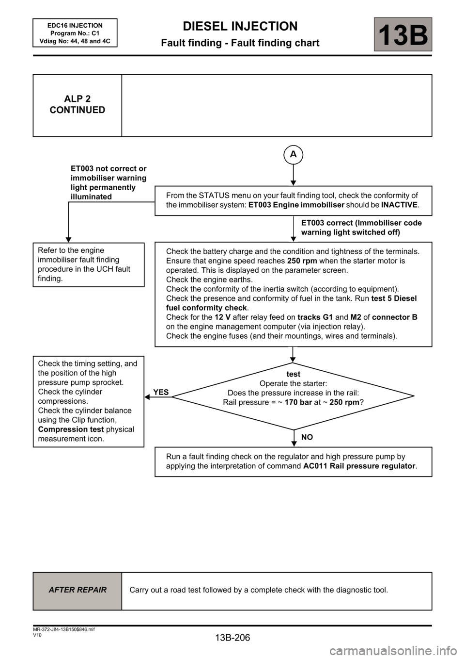
ALP 2
CONTINUED
Refer to the engine
immobiliser fault finding
procedure in the UCH fault
finding.
Check the timing setting, and
the position of the high
pressure pump sprocket.
Check the cylinder
compressions.
Check the cylinder balance
using the Clip function,
Compression test physical
measurement icon.
ET003 not correct or
immobiliser warning
light permanently
illuminated
YESFrom the STATUS menu on your fault finding tool, check the conformity of
the immobiliser system: ET003 Engine immobiliser should be INACTIVE.
ET003 correct (Immobiliser code
warning light switched off)
Check the battery charge and the condition and tightness of the terminals.
Ensure that engine speed reaches 250 rpm when the starter motor is
operated. This is displayed on the parameter screen.
Check the engine earths.
Check the conformity of the inertia switch (according to equipment).
Check the presence and conformity of fuel in the tank. Run test 5 Diesel
fuel conformity check.
Check for the 12 V after relay feed on tracks G1 and M2 of connector B
on the engine management computer (via injection relay).
Check the engine fuses (and their mountings, wires and terminals).
test
Operate the starter:
Does the pressure increase in the rail:
Rail pressure = ~ 170 bar at ~ 250 rpm?
NO
Run a fault finding check on the regulator and high pressure pump by
applying the interpretation of command AC011 Rail pressure regulator.
AFTER REPAIRCarry out a road test followed by a complete check with the diagnostic tool.
EDC16 INJECTION
Program No.: C1
Vdiag No: 44, 48 and 4C
Page 207 of 236
13B-207
MR-372-J84-13B150$846.mif
V10
DIESEL INJECTION
Fault finding - Fault finding chart13B
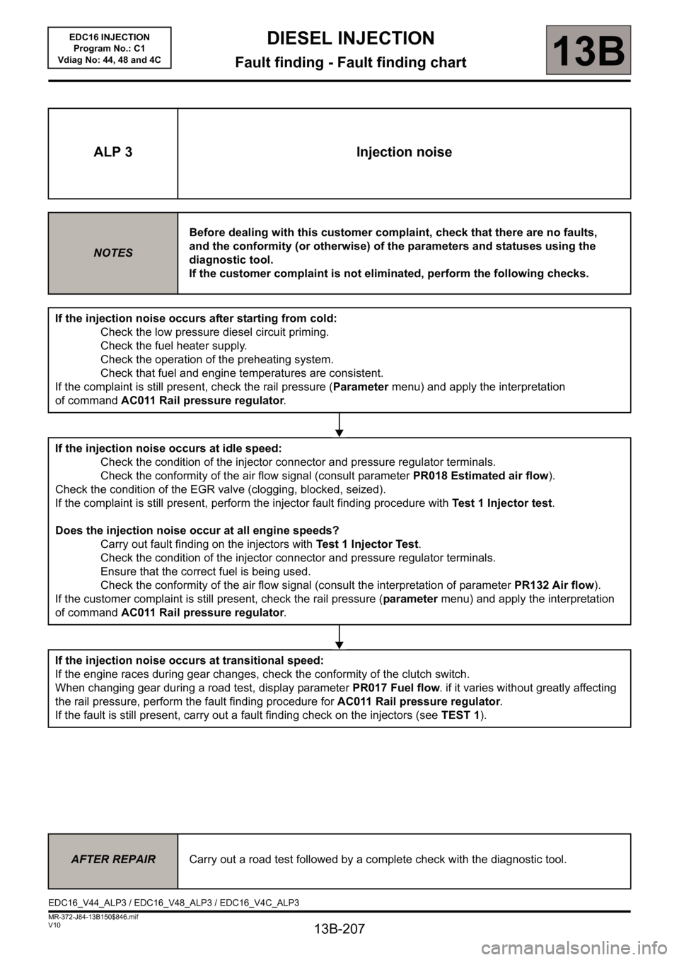
ALP 3 Injection noise
NOTESBefore dealing with this customer complaint, check that there are no faults,
and the conformity (or otherwise) of the parameters and statuses using the
diagnostic tool.
If the customer complaint is not eliminated, perform the following checks.
If the injection noise occurs after starting from cold:
Check the low pressure diesel circuit priming.
Check the fuel heater supply.
Check the operation of the preheating system.
Check that fuel and engine temperatures are consistent.
If the complaint is still present, check the rail pressure (Parameter menu) and apply the interpretation
of command AC011 Rail pressure regulator.
If the injection noise occurs at idle speed:
Check the condition of the injector connector and pressure regulator terminals.
Check the conformity of the air flow signal (consult parameter PR018 Estimated air flow).
Check the condition of the EGR valve (clogging, blocked, seized).
If the complaint is still present, perform the injector fault finding procedure with Test 1 Injector test.
Does the injection noise occur at all engine speeds?
Carry out fault finding on the injectors with Test 1 Injector Test.
Check the condition of the injector connector and pressure regulator terminals.
Ensure that the correct fuel is being used.
Check the conformity of the air flow signal (consult the interpretation of parameter PR132 Air flow).
If the customer complaint is still present, check the rail pressure (parameter menu) and apply the interpretation
of command AC011 Rail pressure regulator.
If the injection noise occurs at transitional speed:
If the engine races during gear changes, check the conformity of the clutch switch.
When changing gear during a road test, display parameter PR017 Fuel flow. if it varies without greatly affecting
the rail pressure, perform the fault finding procedure for AC011 Rail pressure regulator.
If the fault is still present, carry out a fault finding check on the injectors (seeTEST 1).
AFTER REPAIRCarry out a road test followed by a complete check with the diagnostic tool.
EDC16_V44_ALP3 / EDC16_V48_ALP3 / EDC16_V4C_ALP3EDC16 INJECTION
Program No.: C1
Vdiag No: 44, 48 and 4C
Page 218 of 236
13B-218
MR-372-J84-13B150$893.mif
V10
DIESEL INJECTION
Fault finding - Tests
EDC16 INJECTION
Program No.: C1
Vdiag No.: 44, 48 and 4C
13B
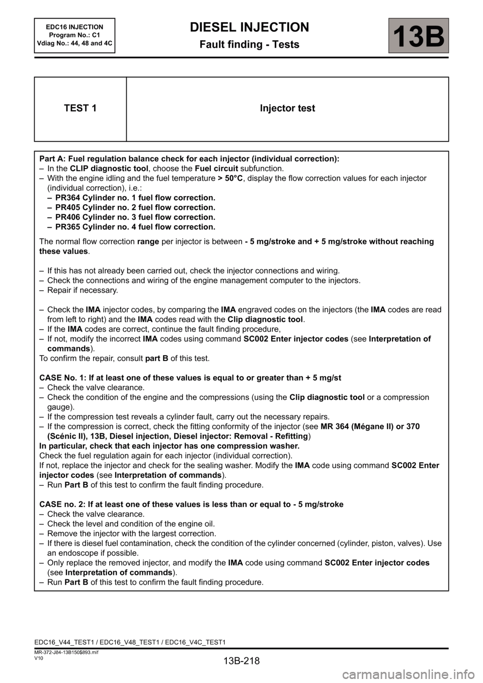
TEST 1 Injector test
Part A: Fuel regulation balance check for each injector (individual correction):
– In the CLIP diagnostic tool, choose the Fuel circuit subfunction.
– With the engine idling and the fuel temperature > 50°C, display the flow correction values for each injector
(individual correction), i.e.:
– PR364 Cylinder no. 1 fuel flow correction.
– PR405 Cylinder no. 2 fuel flow correction.
– PR406 Cylinder no. 3 fuel flow correction.
– PR365 Cylinder no. 4 fuel flow correction.
The normal flow correction range per injector is between - 5 mg/stroke and + 5 mg/stroke without reaching
these values.
– If this has not already been carried out, check the injector connections and wiring.
– Check the connections and wiring of the engine management computer to the injectors.
– Repair if necessary.
– Check the IMA injector codes, by comparing the IMA engraved codes on the injectors (the IMA codes are read
from left to right) and the IMA codes read with the Clip diagnostic tool.
– If the IMA codes are correct, continue the fault finding procedure,
– If not, modify the incorrect IMA codes using command SC002 Enter injector codes (see Interpretation of
commands).
To confirm the repair, consult part B of this test.
CASE No. 1: If at least one of these values is equal to or greater than + 5 mg/st
– Check the valve clearance.
– Check the condition of the engine and the compressions (using the Clip diagnostic tool or a compression
gauge).
– If the compression test reveals a cylinder fault, carry out the necessary repairs.
– If the compression is correct, check the fitting conformity of the injector (see MR 364 (Mégane II) or 370
(Scénic II), 13B, Diesel injection, Diesel injector: Removal - Refitting)
In particular, check that each injector has one compression washer.
Check the fuel regulation again for each injector (individual correction).
If not, replace the injector and check for the sealing washer. Modify the IMA code using command SC002 Enter
injector codes (see Interpretation of commands).
–Run Part B of this test to confirm the fault finding procedure.
CASE no. 2: If at least one of these values is less than or equal to - 5 mg/stroke
– Check the valve clearance.
– Check the level and condition of the engine oil.
– Remove the injector with the largest correction.
– If there is diesel fuel contamination, check the condition of the cylinder concerned (cylinder, piston, valves). Use
an endoscope if possible.
– Only replace the removed injector, and modify the IMA code using command SC002 Enter injector codes
(see Interpretation of commands).
–Run Part B of this test to confirm the fault finding procedure.
EDC16_V44_TEST1 / EDC16_V48_TEST1 / EDC16_V4C_TEST1
Page 225 of 236
13B-225
MR-372-J84-13B150$893.mif
V10
EDC16 INJECTION
Program No.: C1
Vdiag No.: 44, 48 and 4CDIESEL INJECTION
Fault finding - Tests13B
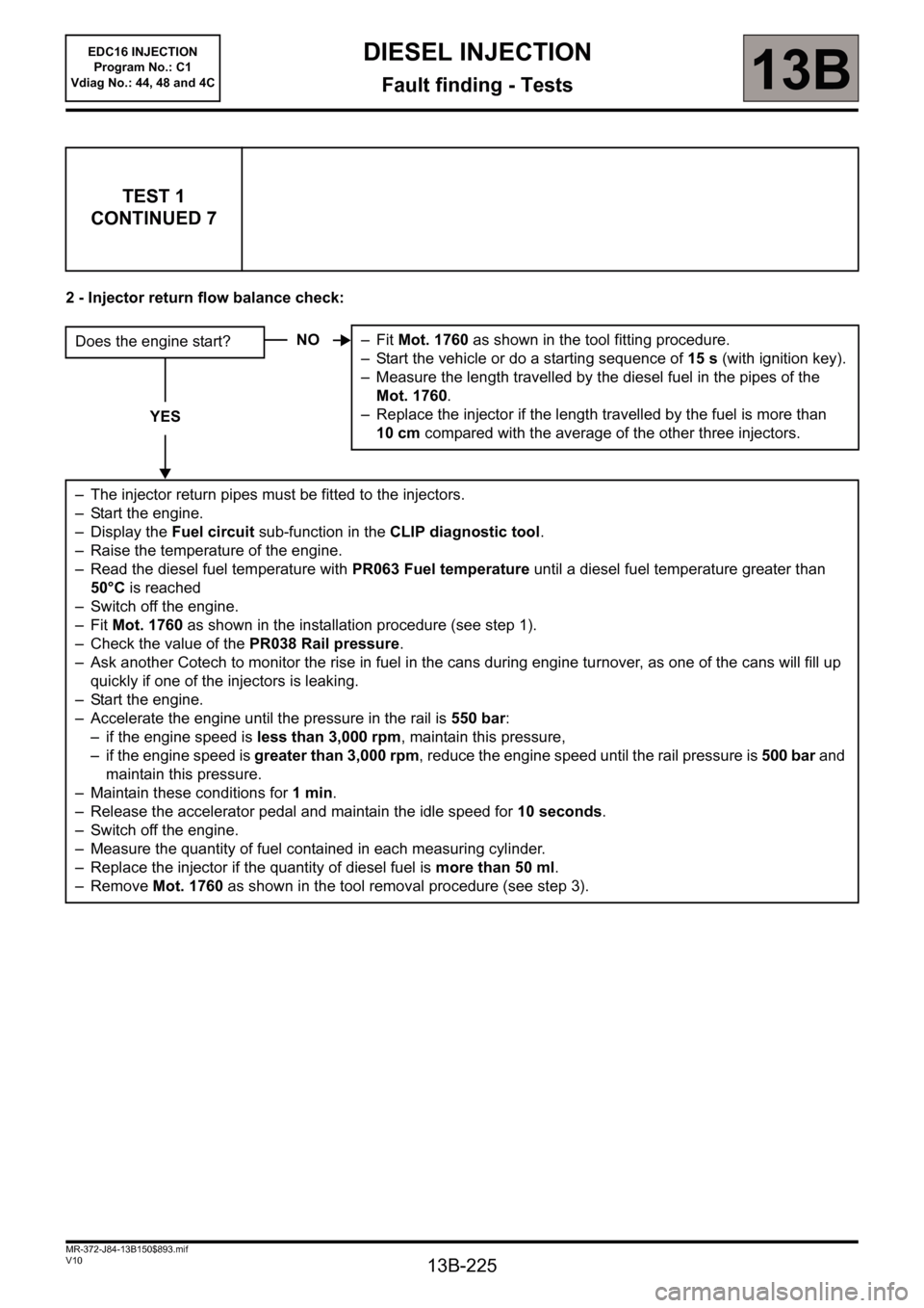
2 - Injector return flow balance check:
TEST 1
CONTINUED 7
Does the engine start?
YES
– The injector return pipes must be fitted to the injectors.
– Start the engine.
– Display the Fuel circuit sub-function in the CLIP diagnostic tool.
– Raise the temperature of the engine.
– Read the diesel fuel temperature with PR063 Fuel temperature until a diesel fuel temperature greater than
50°C is reached
– Switch off the engine.
–Fit Mot. 1760 as shown in the installation procedure (see step 1).
– Check the value of the PR038 Rail pressure.
– Ask another Cotech to monitor the rise in fuel in the cans during engine turnover, as one of the cans will fill up
quickly if one of the injectors is leaking.
– Start the engine.
– Accelerate the engine until the pressure in the rail is 550 bar:
– if the engine speed is less than 3,000 rpm, maintain this pressure,
– if the engine speed is greater than 3,000 rpm, reduce the engine speed until the rail pressure is 500 bar and
maintain this pressure.
– Maintain these conditions for 1min.
– Release the accelerator pedal and maintain the idle speed for 10 seconds.
– Switch off the engine.
– Measure the quantity of fuel contained in each measuring cylinder.
– Replace the injector if the quantity of diesel fuel is more than 50 ml.
– Remove Mot. 1760 as shown in the tool removal procedure (see step 3).NO–Fit Mot. 1760 as shown in the tool fitting procedure.
– Start the vehicle or do a starting sequence of 15 s (with ignition key).
– Measure the length travelled by the diesel fuel in the pipes of the
Mot. 1760.
– Replace the injector if the length travelled by the fuel is more than
10 cm compared with the average of the other three injectors.
Page 231 of 236
13B-231
MR-372-J84-13B150$893.mif
V10
13B
EDC16 INJECTION
Program No.: C1
Vdiag No.: 44, 48 and 4CDIESEL INJECTION
Fault finding - Tests
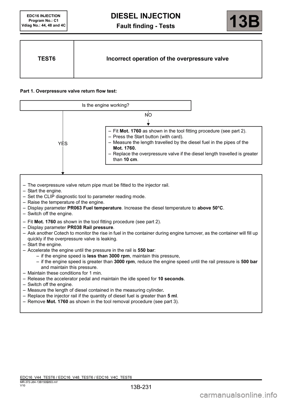
Part 1. Overpressure valve return flow test:
TEST6 Incorrect operation of the overpressure valve
Is the engine working?
–Fit Mot. 1760 as shown in the tool fitting procedure (see part 2).
– Press the Start button (with card).
– Measure the length travelled by the diesel fuel in the pipes of the
Mot. 1760.
– Replace the overpressure valve if the diesel length travelled is greater
than 10 cm.
– The overpressure valve return pipe must be fitted to the injector rail.
– Start the engine.
– Set the CLIP diagnostic tool to parameter reading mode.
– Raise the temperature of the engine.
– Display parameter PR063 Fuel temperature. Increase the diesel temperature to above 50°C.
– Switch off the engine.
–Fit Mot. 1760 as shown in the tool fitting procedure (see part 2).
– Display parameter PR038 Rail pressure.
– Ask another Cotech to monitor the rise in fuel in the container during engine turnover, as the container will fill up
quickly if the overpressure valve is leaking.
– Start the engine.
– Accelerate the engine until the pressure in the rail is 550 bar:
– if the engine speed is less than 3000 rpm, maintain this pressure,
– if the engine speed is greater than 3000 rpm, reduce the engine speed until the rail pressure is 500 bar
and maintain this pressure.
– Maintain these conditions for 1 min.
– Release the accelerator pedal and maintain the idle speed for 10 seconds.
– Switch off the engine.
– Measure the length of diesel contained in the measuring cylinder.
– Replace the injector rail if the quantity of diesel fuel is greater than 5ml.
– Remove Mot. 1760 as shown in the tool removal procedure (see part 3).
NO
YES
EDC16_V44_TEST6 / EDC16_V48_TEST6 / EDC16_V4C_TEST6