sensor RENAULT SCENIC 2011 J95 / 3.G Engine And Peripherals EDC16 Injection Manual Online
[x] Cancel search | Manufacturer: RENAULT, Model Year: 2011, Model line: SCENIC, Model: RENAULT SCENIC 2011 J95 / 3.GPages: 236, PDF Size: 1.32 MB
Page 185 of 236
13B - 185
DIESEL INJECTION
Fault finding - Interpretation of parameters13B
V10 MR-372-J84-13B150$658.mif
EDC16 INJECTION
Program No.: C1
Vdiag No: 44, 48 and 4C
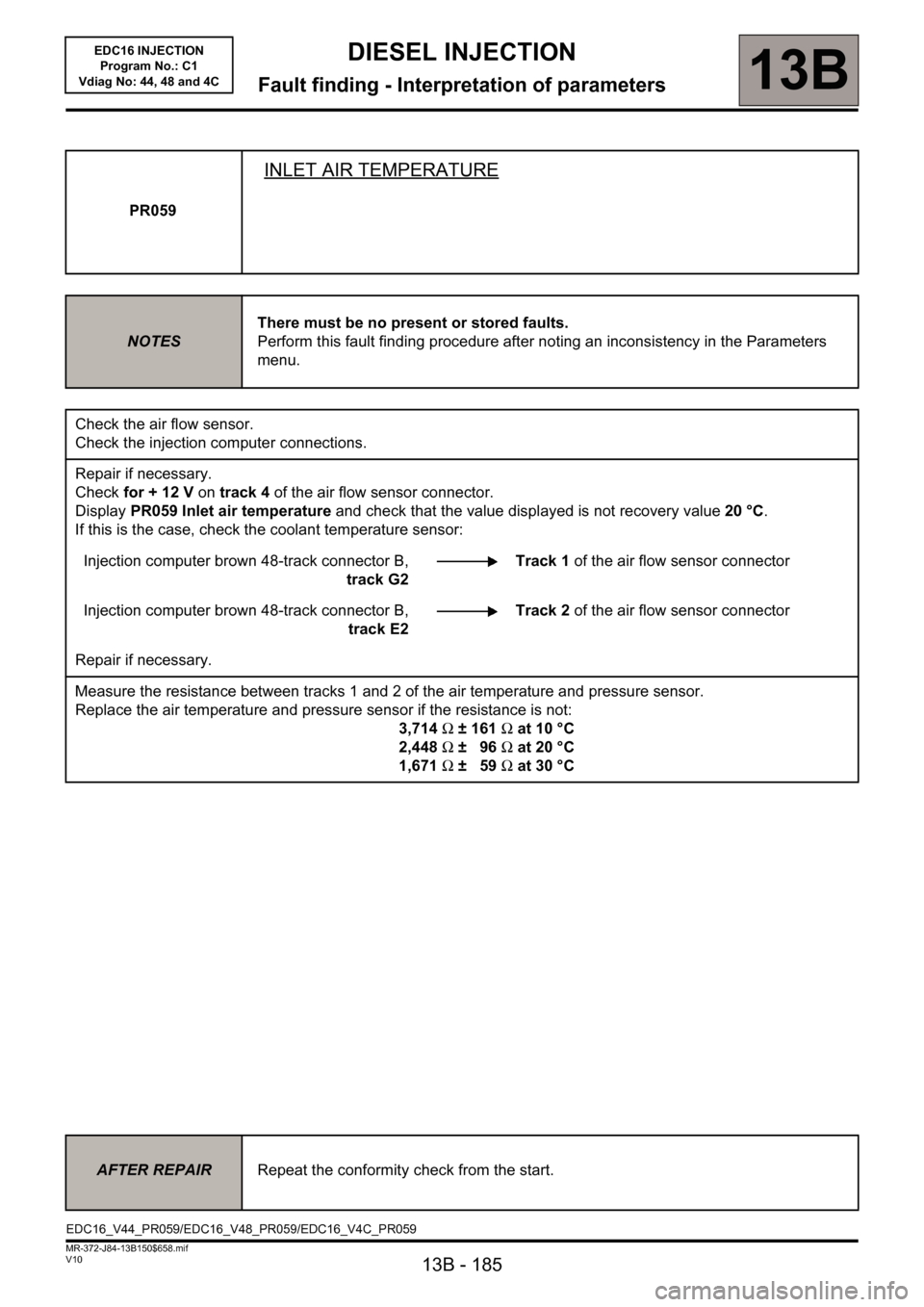
PR059
INLET AIR TEMPERATURE
NOTESThere must be no present or stored faults.
Perform this fault finding procedure after noting an inconsistency in the Parameters
menu.
Check the air flow sensor.
Check the injection computer connections.
Repair if necessary.
Check for + 12 V on track 4 of the air flow sensor connector.
Display PR059 Inlet air temperature and check that the value displayed is not recovery value 20 °C.
If this is the case, check the coolant temperature sensor:
Injection computer brown 48-track connector B,
track G2Track 1 of the air flow sensor connector
Injection computer brown 48-track connector B,
track E2Track 2 of the air flow sensor connector
Repair if necessary.
Measure the resistance between tracks 1 and 2 of the air temperature and pressure sensor.
Replace the air temperature and pressure sensor if the resistance is not:
3,714Ω ±161Ω at 10 °C
2,448Ω ±96Ω at 20 °C
1,671Ω ±59Ω at 30 °C
AFTER REPAIRRepeat the conformity check from the start.
EDC16_V44_PR059/EDC16_V48_PR059/EDC16_V4C_PR059
Page 186 of 236
13B - 186
DIESEL INJECTION
Fault finding - Interpretation of parameters13B
V10 MR-372-J84-13B150$658.mif
EDC16 INJECTION
Program No.: C1
Vdiag No: 44, 48 and 4C
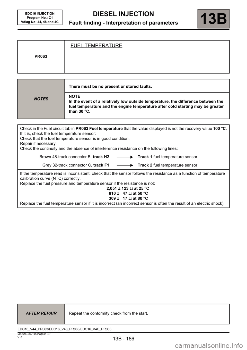
PR063
FUEL TEMPERATURE
NOTESThere must be no present or stored faults.
NOTE
In the event of a relatively low outside temperature, the difference between the
fuel temperature and the engine temperature after cold starting may be greater
than 30 °C.
Check in the Fuel circuit tab in PR063 Fuel temperature that the value displayed is not the recovery value 100 °C.
If it is, check the fuel temperature sensor:
Check that the fuel temperature sensor is in good condition:
Repair if necessary.
Check the continuity and the absence of interference resistance on the following lines:
Brown 48-track connector B, track H2 Track 1 fuel temperature sensor
Grey 32-track connector C, track F1 Track 2 fuel temperature sensor
If the temperature read is inconsistent, check that the sensor follows the resistance as a function of temperature
calibration curve (NTC) correctly.
Replace the fuel pressure and temperature sensor if the resistance is not:
2,051 ± 123Ω at 25 °C
810 ± 47Ω at 50 °C
309 ± 17Ω at 80 °C
Replace the fuel temperature sensor if it is incorrect (an incorrect sensor is often the result of an electric shock).
AFTER REPAIRRepeat the conformity check from the start.
EDC16_V44_PR063/EDC16_V48_PR063/EDC16_V4C_PR063
Page 187 of 236
13B - 187
DIESEL INJECTION
Fault finding - Interpretation of parameters13B
V10 MR-372-J84-13B150$658.mif
EDC16 INJECTION
Program No.: C1
Vdiag No: 44, 48 and 4C
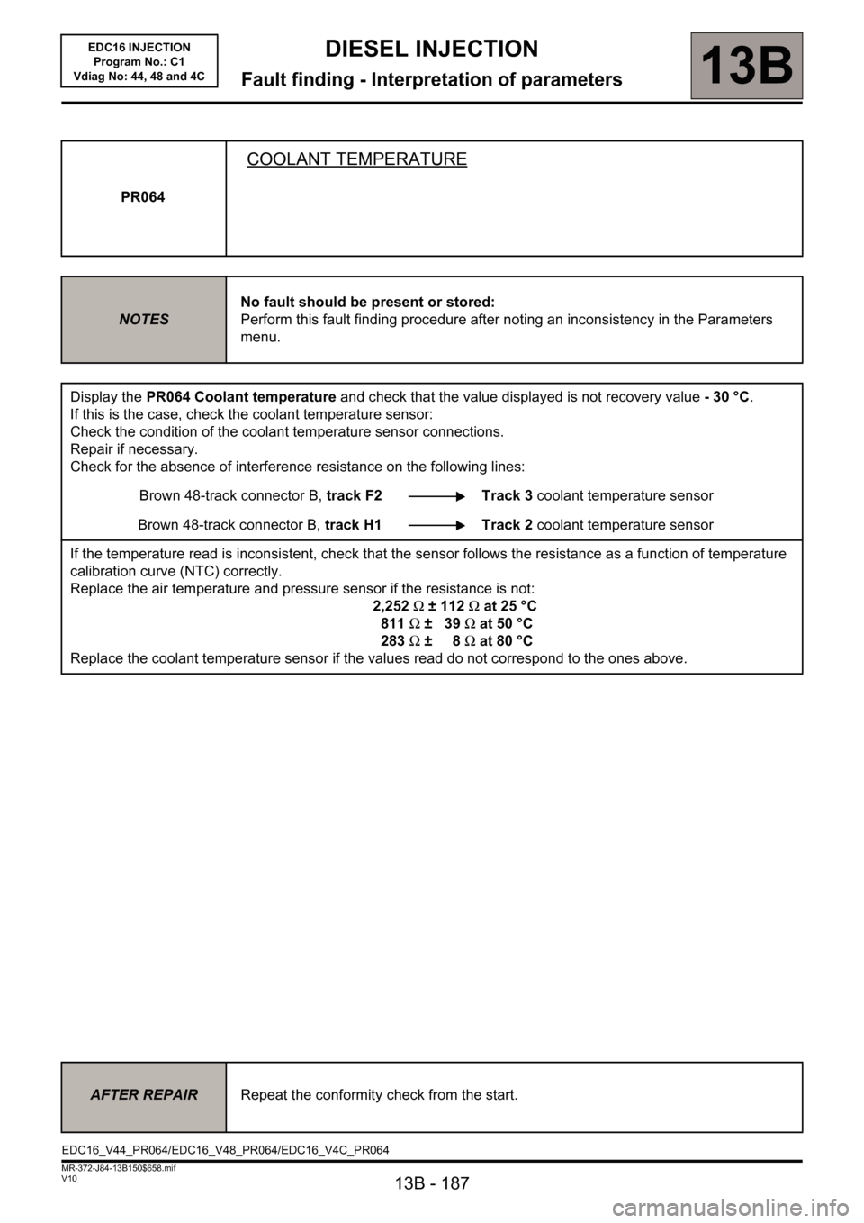
PR064
COOLANT TEMPERATURE
NOTESNo fault should be present or stored:
Perform this fault finding procedure after noting an inconsistency in the Parameters
menu.
Display the PR064 Coolant temperature and check that the value displayed is not recovery value -30°C.
If this is the case, check the coolant temperature sensor:
Check the condition of the coolant temperature sensor connections.
Repair if necessary.
Check for the absence of interference resistance on the following lines:
Brown 48-track connector B, track F2 Track 3 coolant temperature sensor
Brown 48-track connector B, track H1 Track 2 coolant temperature sensor
If the temperature read is inconsistent, check that the sensor follows the resistance as a function of temperature
calibration curve (NTC) correctly.
Replace the air temperature and pressure sensor if the resistance is not:
2,252Ω ± 112Ω at 25 °C
811Ω ±39Ω at 50 °C
283Ω ±8Ω at 80 °C
Replace the coolant temperature sensor if the values read do not correspond to the ones above.
AFTER REPAIRRepeat the conformity check from the start.
EDC16_V44_PR064/EDC16_V48_PR064/EDC16_V4C_PR064
Page 197 of 236
13B - 197
DIESEL INJECTION
Fault finding - Interpretation of commands13B
V10 MR-372-J84-13B150$752.mif
EDC16 INJECTION
Program No.: C1
Vdiag No: 44, 48 and 4C
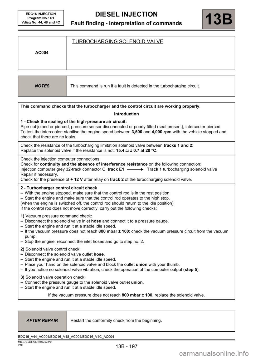
AC004
TURBOCHARGING SOLENOID VALVE
NOTESThis command is run if a fault is detected in the turbocharging circuit.
This command checks that the turbocharger and the control circuit are working properly.
Introduction
1 - Check the sealing of the high-pressure air circuit:
Pipe not joined or pierced, pressure sensor disconnected or poorly fitted (seal present), intercooler pierced.
To test the intercooler: stabilise the engine speed between 3,500 and 4,000 rpm with the vehicle stopped and
check that there are no leaks.
Check the resistance of the turbocharging limitation solenoid valve between tracks 1 and 2:
Replace the solenoid valve if the resistance is not: 15.4 Ω ± 0.7 at 20 °C.
Check the injection computer connections.
Check for continuity and the absence of interference resistance on the following connection:
Injection computer grey 32-track connector C, track E1 Track 1 turbocharging solenoid valve
Repair if necessary.
Check for the presence of +12V after relay on track 2 of the turbocharging solenoid valve.
2 - Turbocharger control circuit check
– With the engine stopped, make sure that the control rod is in the rest position.
– Start the engine and make sure that the control rod operates to the high stop.
(when the engine is switched off, the control rod should return to the idle position)
If the control rod does not move correctly, carry out the following checks:
1) Vacuum pressure command check:
– Disconnect the solenoid valve inlet hose and connect it to a pressure gauge.
– Start the engine and run it at a stable idle speed.
– If the vacuum pressure does not reach 800 mbar ± 100: check the vacuum pressure circuit from the vacuum
pump.
– Stop the engine, reconnect the inlet hoses and go to step no. 2.
2) Solenoid valve control check:
– Disconnect the solenoid valve outlet hose.
– Start the engine and run it at a stable idle speed.
– Place your hand on the solenoid valve and block the outlet union with your thumb.
– If you notice no solenoid valve vibration, check the operation of the computer output (step 5).
3) Solenoid valve operation check:
– Connect the pressure gauge to the solenoid valve outlet union.
– Start the engine and run it at a stable idle speed.
If the vacuum pressure does not reach 800 mbar ± 100, replace the solenoid valve.
AFTER REPAIRRestart the conformity check from the beginning.
EDC16_V44_AC004/EDC16_V48_AC004/EDC16_V4C_AC004
Page 200 of 236
13B - 200
DIESEL INJECTION
Fault finding - Interpretation of commands13B
V10 MR-372-J84-13B150$752.mif
EDC16 INJECTION
Program No.: C1
Vdiag No: 44, 48 and 4C
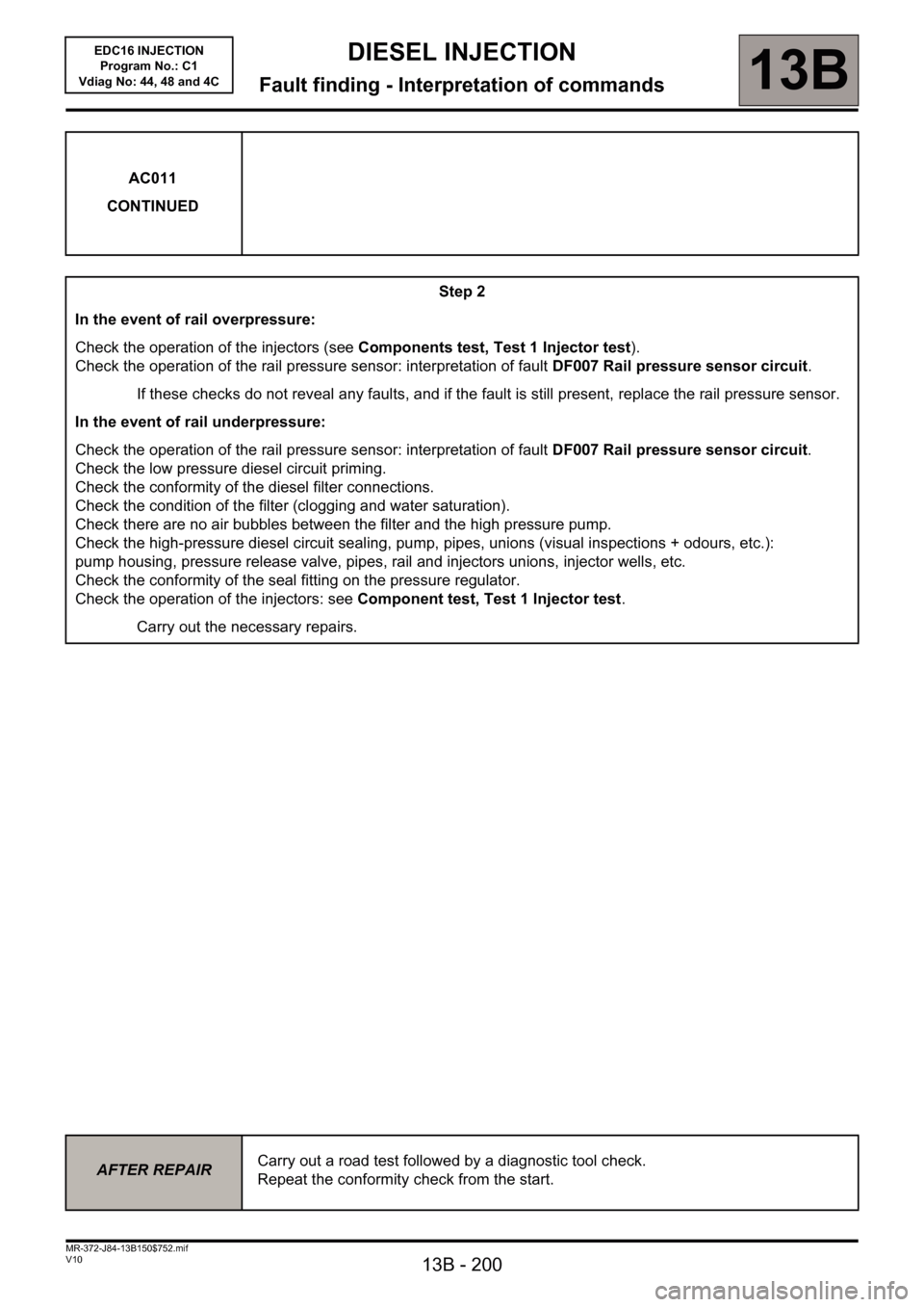
AC011
CONTINUED
Step 2
In the event of rail overpressure:
Check the operation of the injectors (see Components test, Test 1 Injector test).
Check the operation of the rail pressure sensor: interpretation of fault DF007 Rail pressure sensor circuit.
If these checks do not reveal any faults, and if the fault is still present, replace the rail pressure sensor.
In the event of rail underpressure:
Check the operation of the rail pressure sensor: interpretation of fault DF007 Rail pressure sensor circuit.
Check the low pressure diesel circuit priming.
Check the conformity of the diesel filter connections.
Check the condition of the filter (clogging and water saturation).
Check there are no air bubbles between the filter and the high pressure pump.
Check the high-pressure diesel circuit sealing, pump, pipes, unions (visual inspections + odours, etc.):
pump housing, pressure release valve, pipes, rail and injectors unions, injector wells, etc.
Check the conformity of the seal fitting on the pressure regulator.
Check the operation of the injectors: see Component test, Test 1 Injector test.
Carry out the necessary repairs.
AFTER REPAIRCarry out a road test followed by a diagnostic tool check.
Repeat the conformity check from the start.
Page 205 of 236
13B-205
MR-372-J84-13B150$846.mif
V10
DIESEL INJECTION
Fault finding - Fault finding chart13B
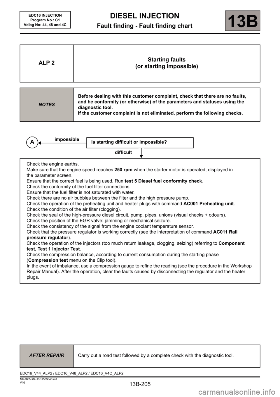
ALP 2Starting faults
(or starting impossible)
NOTESBefore dealing with this customer complaint, check that there are no faults,
and he conformity (or otherwise) of the parameters and statuses using the
diagnostic tool.
If the customer complaint is not eliminated, perform the following checks.
Is starting difficult or impossible?
difficult
Check the engine earths.
Make sure that the engine speed reaches 250 rpm when the starter motor is operated, displayed in
the parameter screen.
Ensure that the correct fuel is being used. Run test 5 Diesel fuel conformity check.
Check the conformity of the fuel filter connections.
Ensure that the fuel filter is not saturated with water.
Check there are no air bubbles between the filter and the high pressure pump.
Check the operation of the preheating unit and heater plugs with command AC001 Preheating unit.
Check the condition of the air filter (clogging).
Check the seal of the high-pressure diesel circuit, pump, pipes, unions (visual checks + odours).
Check the position of the EGR valve: jamming or mechanical seizure.
Check the consistency of the signal from the engine coolant temperature sensor.
Check that the pressure regulator is working correctly (see the interpretation of command AC011 Rail
pressure regulator).
Check the operation of the injectors (too much return leakage, clogging, seizing) referring to Component
test, Test 1 Injector Test.
Check the compression balance, according to current consumption during the starting phase
(Compression test menu on the Clip tool).
In the event of imbalance, use a compression gauge to refine the reading (see the procedure in the Workshop
Repair Manual). After the operation, clear the faults caused by disconnecting the regulator and the heater
plugs.
impossible
AFTER REPAIRCarry out a road test followed by a complete check with the diagnostic tool.
EDC16_V44_ALP2 / EDC16_V48_ALP2 / EDC16_V4C_ALP2
EDC16 INJECTION
Program No.: C1
Vdiag No: 44, 48 and 4C
Page 208 of 236
13B-208
MR-372-J84-13B150$846.mif
V10
DIESEL INJECTION
Fault finding - Fault finding chart13B
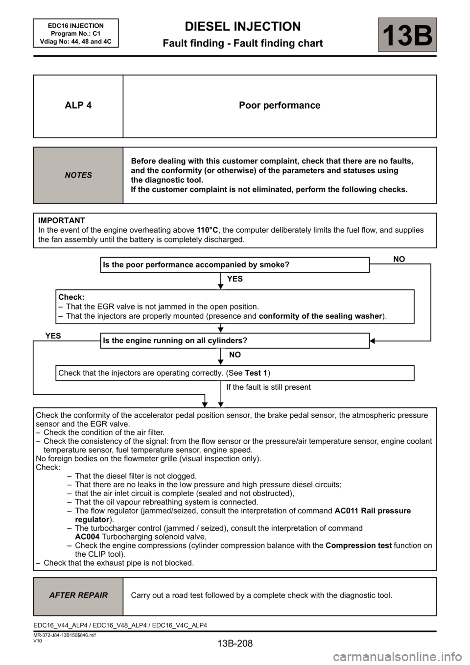
ALP 4 Poor performance
NOTESBefore dealing with this customer complaint, check that there are no faults,
and the conformity (or otherwise) of the parameters and statuses using
the diagnostic tool.
If the customer complaint is not eliminated, perform the following checks.
IMPORTANT
In the event of the engine overheating above 11 0 ° C, the computer deliberately limits the fuel flow, and supplies
the fan assembly until the battery is completely discharged.
Is the poor performance accompanied by smoke?
YES
Check:
– That the EGR valve is not jammed in the open position.
– That the injectors are properly mounted (presence and conformity of the sealing washer).
Is the engine running on all cylinders?
NO
Check that the injectors are operating correctly. (See Test 1)
If the fault is still present
Check the conformity of the accelerator pedal position sensor, the brake pedal sensor, the atmospheric pressure
sensor and the EGR valve.
– Check the condition of the air filter.
– Check the consistency of the signal: from the flow sensor or the pressure/air temperature sensor, engine coolant
temperature sensor, fuel temperature sensor, engine speed.
No foreign bodies on the flowmeter grille (visual inspection only).
Check:
– That the diesel filter is not clogged.
– That there are no leaks in the low pressure and high pressure diesel circuits;
– that the air inlet circuit is complete (sealed and not obstructed),
– That the oil vapour rebreathing system is connected.
– The flow regulator (jammed/seized, consult the interpretation of command AC011 Rail pressure
regulator).
– The turbocharger control (jammed / seized), consult the interpretation of command
AC004Turbocharging solenoid valve,
– Check the engine compressions (cylinder compression balance with the Compression test function on
the CLIP tool).
– Check that the exhaust pipe is not blocked.
NO
YES
AFTER REPAIRCarry out a road test followed by a complete check with the diagnostic tool.
EDC16_V44_ALP4 / EDC16_V48_ALP4 / EDC16_V4C_ALP4
EDC16 INJECTION
Program No.: C1
Vdiag No: 44, 48 and 4C
Page 210 of 236
13B-210
MR-372-J84-13B150$846.mif
V10
DIESEL INJECTION
Fault finding - Fault finding chart13B
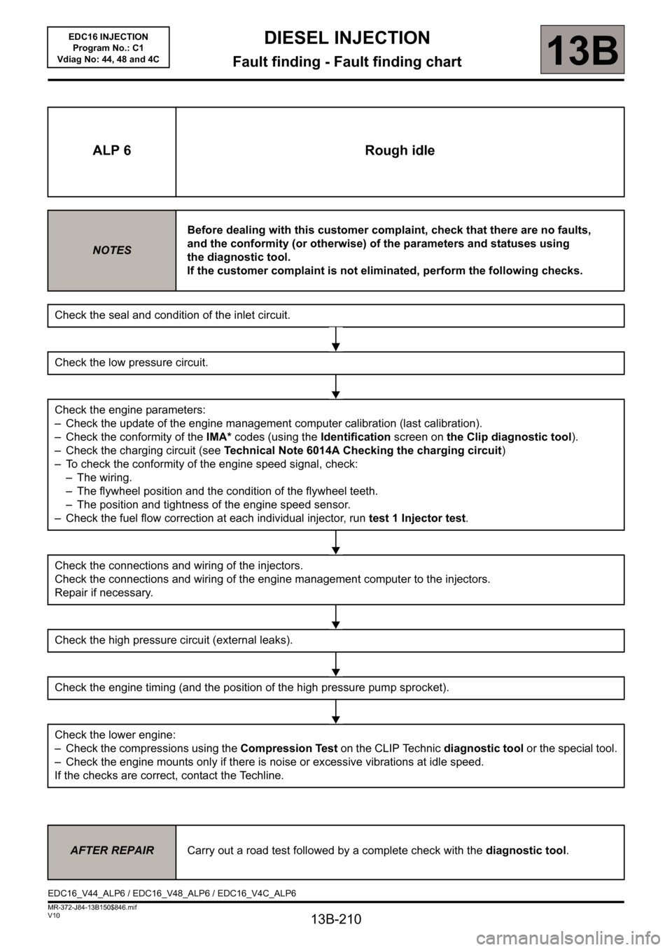
ALP 6 Rough idle
NOTESBefore dealing with this customer complaint, check that there are no faults,
and the conformity (or otherwise) of the parameters and statuses using
the diagnostic tool.
If the customer complaint is not eliminated, perform the following checks.
Check the seal and condition of the inlet circuit.
Check the low pressure circuit.
Check the engine parameters:
– Check the update of the engine management computer calibration (last calibration).
– Check the conformity of the IMA* codes (using the Identification screen on the Clip diagnostic tool).
– Check the charging circuit (see Technical Note 6014A Checking the charging circuit)
– To check the conformity of the engine speed signal, check:
– The wiring.
– The flywheel position and the condition of the flywheel teeth.
– The position and tightness of the engine speed sensor.
– Check the fuel flow correction at each individual injector, run test 1 Injector test.
Check the connections and wiring of the injectors.
Check the connections and wiring of the engine management computer to the injectors.
Repair if necessary.
Check the high pressure circuit (external leaks).
Check the engine timing (and the position of the high pressure pump sprocket).
Check the lower engine:
– Check the compressions using the Compression Test on the CLIP Technic diagnostic tool or the special tool.
– Check the engine mounts only if there is noise or excessive vibrations at idle speed.
If the checks are correct, contact the Techline.
AFTER REPAIRCarry out a road test followed by a complete check with the diagnostic tool.
EDC16_V44_ALP6 / EDC16_V48_ALP6 / EDC16_V4C_ALP6EDC16 INJECTION
Program No.: C1
Vdiag No: 44, 48 and 4C
Page 228 of 236
13B-228
MR-372-J84-13B150$893.mif
V10
EDC16 INJECTION
Program No.: C1
Vdiag No.: 44, 48 and 4CDIESEL INJECTION
Fault finding - Tests13B
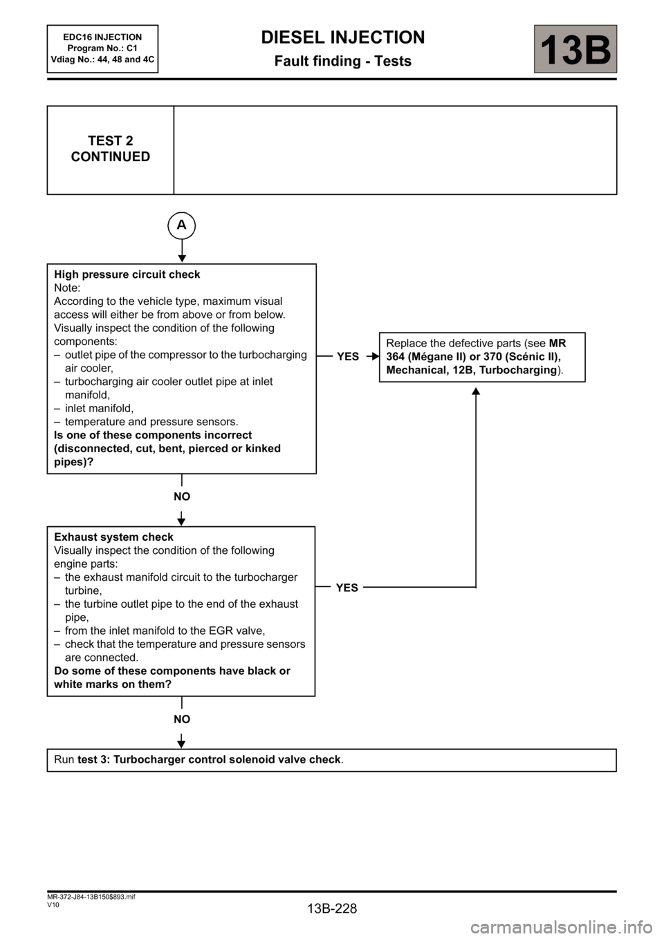
TEST 2
CONTINUED
High pressure circuit check
Note:
According to the vehicle type, maximum visual
access will either be from above or from below.
Visually inspect the condition of the following
components:
– outlet pipe of the compressor to the turbocharging
air cooler,
– turbocharging air cooler outlet pipe at inlet
manifold,
– inlet manifold,
– temperature and pressure sensors.
Is one of these components incorrect
(disconnected, cut, bent, pierced or kinked
pipes)?
NO
Exhaust system check
Visually inspect the condition of the following
engine parts:
– the exhaust manifold circuit to the turbocharger
turbine,
– the turbine outlet pipe to the end of the exhaust
pipe,
– from the inlet manifold to the EGR valve,
– check that the temperature and pressure sensors
are connected.
Do some of these components have black or
white marks on them?
NO
Run test 3: Turbocharger control solenoid valve check.
YESReplace the defective parts (see MR
364 (Mégane II) or 370 (Scénic II),
Mechanical, 12B, Turbocharging).
YES
Page 236 of 236
13B-236
DIESEL INJECTION
Fault finding - Glossary13B
V10 MR-372-J84-13B150$940.mif
EDC16 INJECTION
Program No.: C1
Vdiag No: 44, 48 and 4CDIESEL INJECTION
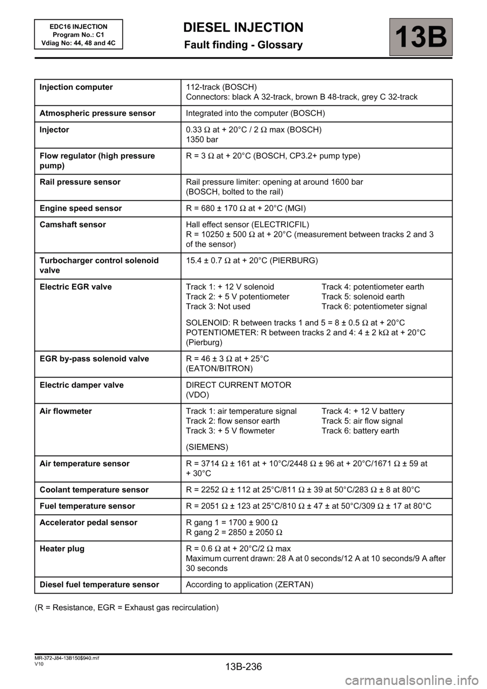
Fault finding - Glossary
(R = Resistance, EGR = Exhaust gas recirculation)Injection computer112-track (BOSCH)
Connectors: black A 32-track, brown B 48-track, grey C 32-track
Atmospheric pressure sensorIntegrated into the computer (BOSCH)
Injector0.33Ω at + 20°C / 2Ω max (BOSCH)
1350 bar
Flow regulator (high pressure
pump)R= 3Ω at + 20°C (BOSCH, CP3.2+ pump type)
Rail pressure sensorRail pressure limiter: opening at around 1600 bar
(BOSCH, bolted to the rail)
Engine speed sensorR = 680 ± 170Ω at + 20°C (MGI)
Camshaft sensorHall effect sensor (ELECTRICFIL)
R = 10250 ± 500Ω at + 20°C (measurement between tracks 2 and 3
of the sensor)
Turbocharger control solenoid
valve15.4 ± 0.7Ω at + 20°C (PIERBURG)
Electric EGR valveTrack 1: + 12 V solenoid
Track 2: + 5 V potentiometer
Track 3: Not usedTrack 4: potentiometer earth
Track 5: solenoid earth
Track 6: potentiometer signal
SOLENOID: R between tracks 1 and 5 = 8 ± 0.5Ω at + 20°C
POTENTIOMETER: R between tracks 2 and 4: 4 ± 2 kΩ at + 20°C
(Pierburg)
EGR by-pass solenoid valveR= 46 ±3Ω at + 25°C
(EATON/BITRON)
Electric damper valveDIRECT CURRENT MOTOR
(VDO)
Air flowmeterTrack 1: air temperature signal
Track 2: flow sensor earth
Track 3: + 5 V flowmeterTrack 4: + 12 V battery
Track 5: air flow signal
Track 6: battery earth
(SIEMENS)
Air temperature sensorR = 3714Ω ± 161 at + 10°C/2448Ω ± 96 at + 20°C/1671Ω ± 59 at
+30°C
Coolant temperature sensorR = 2252Ω ± 112 at 25°C/811Ω ± 39 at 50°C/283Ω ±8 at 80°C
Fuel temperature sensorR = 2051Ω ± 123 at 25°C/810Ω ± 47 ± at 50°C/309Ω ± 17 at 80°C
Accelerator pedal sensorR gang 1 = 1700 ± 900Ω
R gang 2 = 2850 ± 2050Ω
Heater plugR= 0.6Ω at + 20°C/2Ω max
Maximum current drawn: 28 A at 0 seconds/12 A at 10 seconds/9 A after
30 seconds
Diesel fuel temperature sensorAccording to application (ZERTAN)
MR-372-J84-13B150$940.mif