alternator RENAULT SCENIC 2011 J95 / 3.G Engine And Peripherals EDC16 Injection Workshop Manual
[x] Cancel search | Manufacturer: RENAULT, Model Year: 2011, Model line: SCENIC, Model: RENAULT SCENIC 2011 J95 / 3.GPages: 236, PDF Size: 1.32 MB
Page 8 of 236
13B - 8
DIESEL INJECTION
Fault finding - Introduction13B
V10 MR-372-J84-13B150$047.mif
EDC16 INJECTION
Program No.: C1
Vdiag No.: 44, 48 and 4C
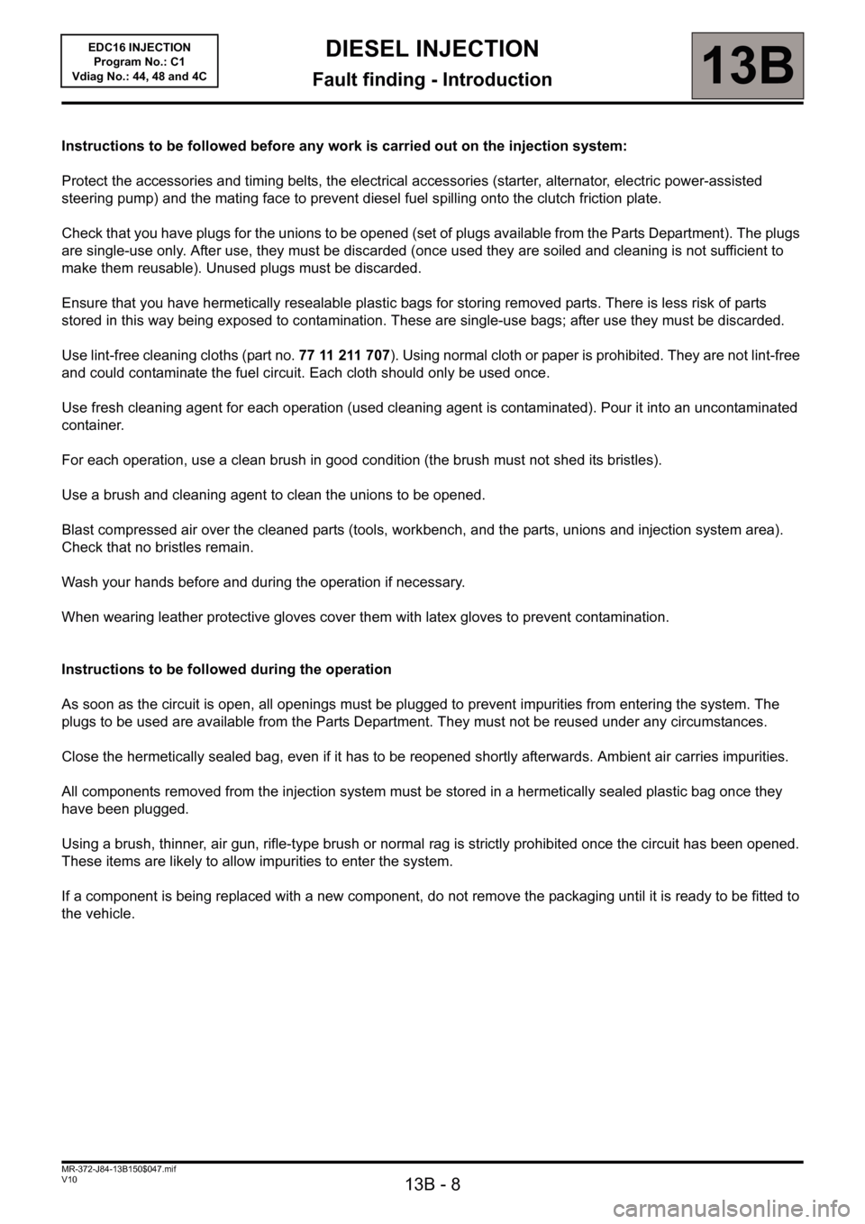
Instructions to be followed before any work is carried out on the injection system:
Protect the accessories and timing belts, the electrical accessories (starter, alternator, electric power-assisted
steering pump) and the mating face to prevent diesel fuel spilling onto the clutch friction plate.
Check that you have plugs for the unions to be opened (set of plugs available from the Parts Department). The plugs
are single-use only. After use, they must be discarded (once used they are soiled and cleaning is not sufficient to
make them reusable). Unused plugs must be discarded.
Ensure that you have hermetically resealable plastic bags for storing removed parts. There is less risk of parts
stored in this way being exposed to contamination. These are single-use bags; after use they must be discarded.
Use lint-free cleaning cloths (part no. 77 11 211 707). Using normal cloth or paper is prohibited. They are not lint-free
and could contaminate the fuel circuit. Each cloth should only be used once.
Use fresh cleaning agent for each operation (used cleaning agent is contaminated). Pour it into an uncontaminated
container.
For each operation, use a clean brush in good condition (the brush must not shed its bristles).
Use a brush and cleaning agent to clean the unions to be opened.
Blast compressed air over the cleaned parts (tools, workbench, and the parts, unions and injection system area).
Check that no bristles remain.
Wash your hands before and during the operation if necessary.
When wearing leather protective gloves cover them with latex gloves to prevent contamination.
Instructions to be followed during the operation
As soon as the circuit is open, all openings must be plugged to prevent impurities from entering the system. The
plugs to be used are available from the Parts Department. They must not be reused under any circumstances.
Close the hermetically sealed bag, even if it has to be reopened shortly afterwards. Ambient air carries impurities.
All components removed from the injection system must be stored in a hermetically sealed plastic bag once they
have been plugged.
Using a brush, thinner, air gun, rifle-type brush or normal rag is strictly prohibited once the circuit has been opened.
These items are likely to allow impurities to enter the system.
If a component is being replaced with a new component, do not remove the packaging until it is ready to be fitted to
the vehicle.
Page 51 of 236
DIESEL INJECTION
Fault finding - Interpretation of faults13B
13B-51V10 MR-372-J84-13B150$282.mif
EDC16 INJECTION
Program No.: C1
Vdiag No.: 44, 48 and 4C
DF038
CONTINUED
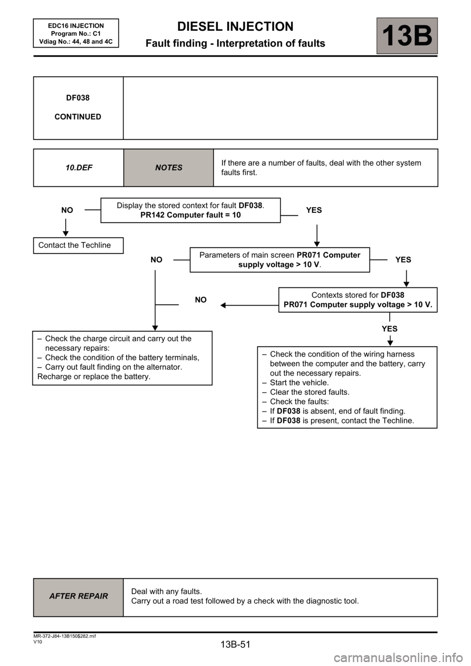
10.DEF
NOTESIf there are a number of faults, deal with the other system
faults first.
NODisplay the stored context for fault DF038.
PR142 Computer fault = 10YES
Contact the Techline
NOParameters of main screen PR071 Computer
supply voltage > 10 V.YES
NOContexts stored for DF038
PR071 Computer supply voltage > 10 V.
YES
– Check the condition of the wiring harness
between the computer and the battery, carry
out the necessary repairs.
– Start the vehicle.
– Clear the stored faults.
– Check the faults:
– If DF038 is absent, end of fault finding.
– If DF038 is present, contact the Techline.
– Check the charge circuit and carry out the
necessary repairs:
– Check the condition of the battery terminals,
– Carry out fault finding on the alternator.
Recharge or replace the battery.
AFTER REPAIRDeal with any faults.
Carry out a road test followed by a check with the diagnostic tool.
Page 59 of 236
13B-59
DIESEL INJECTION
Fault finding - Interpretation of faults13B
V10 MR-372-J84-13B150$329.mif
EDC16 INJECTION
Program No.: C1
Vdiag No.: 44, 48 and 4C
DF046
PRESENT
OR
STOREDBATTERY VOLTAGE
1.DEF : excess voltage
2.DEF : undervoltage
NOTESConditions for applying the fault finding procedure to a stored fault:
The fault is declared present following a road test or after attempting to start the engine.
Special notes:
Computer operating voltage: 9 V < operating voltage < 16 V.
If the battery voltage is too low this may cause the level 1 fault warning light to
come on.
It is then not possible to start the engine.
Use bornier Ele. 1681 for all operations on the injection computer connectors.
1.DEF
NOTESNone.
Check the charge circuits: – battery status,
– alternator status (complete fault finding procedure).
Carry out the necessary repairs.
2.DEF
NOTES(Use the Wiring Diagrams Technical Note for the vehicle).
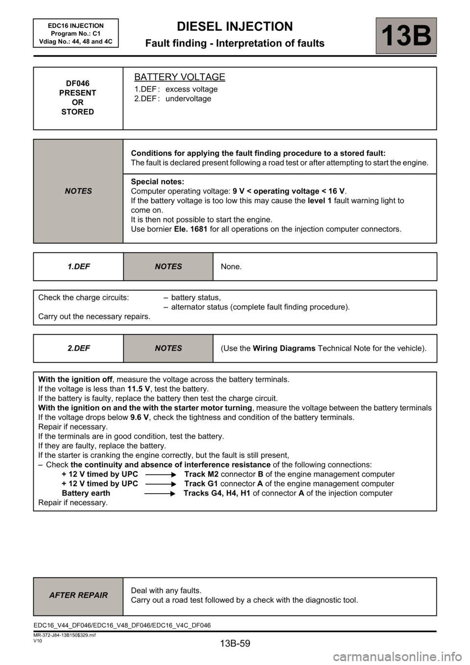
With the ignition off, measure the voltage across the battery terminals.
If the voltage is less than 11.5 V, test the battery.
If the battery is faulty, replace the battery then test the charge circuit.
With the ignition on and the with the starter motor turning, measure the voltage between the battery terminals
If the voltage drops below 9.6 V, check the tightness and condition of the battery terminals.
Repair if necessary.
If the terminals are in good condition, test the battery.
If they are faulty, replace the battery.
If the starter is cranking the engine correctly, but the fault is still present,
–Check the continuity and absence of interference resistance of the following connections:
+ 12 V timed by UPC Track M2 connector B of the engine management computer
+ 12 V timed by UPC Track G1 connector A of the engine management computer
Battery earth Tracks G4, H4, H1 of connectorA of the injection computer
Repair if necessary.
AFTER REPAIRDeal with any faults.
Carry out a road test followed by a check with the diagnostic tool.
EDC16_V44_DF046/EDC16_V48_DF046/EDC16_V4C_DF046
Page 110 of 236
13B-110
DIESEL INJECTION
Fault finding - Conformity check13B
V10 MR-372-J84-13B150$423.mif
EDC16 INJECTION
Program No.: C1
Vdiag No: 44, 48 and 4C
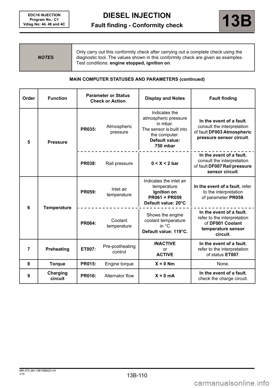
MAIN COMPUTER STATUSES AND PARAMETERS (continued)
NOTESOnly carry out this conformity check after carrying out a complete check using the
diagnostic tool. The values shown in this conformity check are given as examples.
Test conditions: engine stopped, ignition on.
Order FunctionParameter or Status
Check or ActionDisplay and Notes Fault finding
5 PressurePR035:Atmospheric
pressureIndicates the
atmospheric pressure
in mbar.
The sensor is built into
the computer.
Default value:
750 mbarIn the event of a fault,
consult the interpretation
of fault DF003 Atmospheric
pressure sensor circuit.
PR038:Rail pressure0
of fault DF007 Rail pressure
sensor circuit.
6 TemperaturePR059: Inlet air
temperatureIndicates the inlet air
temperature
Ignition on
PR061 = PR059
Default value: 20°C In the event of a fault, refer
to the interpretation
of parameter PR059.
PR064: Coolant
temperatureShows the engine
coolant temperature
in °C
Default value: 119°C.In the event of a fault,
refer to the interpretation
ofDF001 Coolant
temperature sensor
circuit.
7 Preheating ET007: Pre-postheating
controlINACTIVE
or
ACTIVEIn the event of a fault,
refer to the interpretation
of statusET007.
8 Torque PR015: Engine torqueX = 0 NmNone.
9Charging
circuit PR016:Alternator flow X = 0 mAIn the event of a fault,
check the charge circuit.
Page 129 of 236
13B-129
DIESEL INJECTION
Fault finding - Conformity check13B
V10 MR-372-J84-13B150$423.mif
EDC16 INJECTION
Program No.: C1
Vdiag No: 44, 48 and 4C
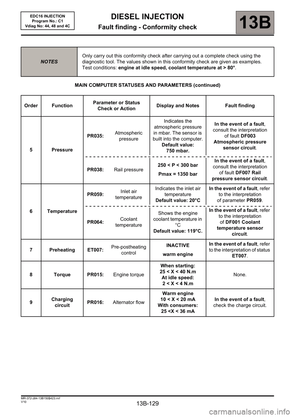
MAIN COMPUTER STATUSES AND PARAMETERS (continued)
NOTESOnly carry out this conformity check after carrying out a complete check using the
diagnostic tool. The values shown in this conformity check are given as examples.
Test conditions: engine at idle speed, coolant temperature at > 80°.
Order FunctionParameter or Status
Check or ActionDisplay and Notes Fault finding
5PressurePR035: Atmospheric
pressureIndicates the
atmospheric pressure
in mbar. The sensor is
built into the computer.
Default value:
750 mbar.In the event of a fault,
consult the interpretation
of fault DF003
Atmospheric pressure
sensor circuit.
PR038: Rail pressure250< P< 300bar
Pmax = 1350 barIn the event of a fault,
consult the interpretation
of fault DF007 Rail
pressure sensor circuit.
6 TemperaturePR059: Inlet air
temperatureIndicates the inlet air
temperature
Default value: 20°CIn the event of a fault, refer
to the interpretation
of parameter PR059.
PR064: Coolant
temperatureShows the engine
coolant temperature in
°C
Default value: 119°C.In the event of a fault, refer
to the interpretation
ofDF001 Coolant
temperature sensor
circuit.
7 Preheating ET007: Pre-postheating
controlINACTIVE
warm engineIn the event of a fault, refer
to the interpretation of status
ET007.
8 Torque PR015: Engine torqueWhen starting:
25 < X < 40 N.m
At idle speed:
2
circuitPR016: Alternator flowWarm engine
10 < X < 20 mA
With consumers:
25
Page 180 of 236
13B - 180
DIESEL INJECTION
Fault finding - Parameter summary table13B
V10 MR-372-J84-13B150$611.mif
EDC16 INJECTION
Program No.: C1
Vdiag No.: 44, 48 and 4CDIESEL INJECTION
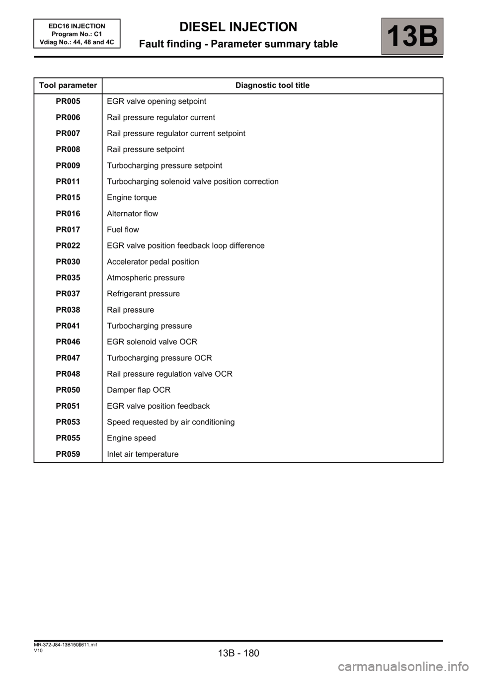
Fault finding - Parameter summary table
Tool parameter Diagnostic tool title
PR005EGR valve opening setpoint
PR006Rail pressure regulator current
PR007Rail pressure regulator current setpoint
PR008Rail pressure setpoint
PR009Turbocharging pressure setpoint
PR011Turbocharging solenoid valve position correction
PR015Engine torque
PR016Alternator flow
PR017Fuel flow
PR022EGR valve position feedback loop difference
PR030Accelerator pedal position
PR035Atmospheric pressure
PR037Refrigerant pressure
PR038Rail pressure
PR041Turbocharging pressure
PR046EGR solenoid valve OCR
PR047Turbocharging pressure OCR
PR048Rail pressure regulation valve OCR
PR050Damper flap OCR
PR051EGR valve position feedback
PR053Speed requested by air conditioning
PR055Engine speed
PR059Inlet air temperature
MR-372-J84-13B150$611.mif