coolant level RENAULT SCENIC 2011 J95 / 3.G Engine And Peripherals EDC16 Injection Workshop Manual
[x] Cancel search | Manufacturer: RENAULT, Model Year: 2011, Model line: SCENIC, Model: RENAULT SCENIC 2011 J95 / 3.GPages: 236, PDF Size: 1.32 MB
Page 12 of 236

13B - 12
DIESEL INJECTION
Fault finding - System operation13B
V10 MR-372-J84-13B150$094.mif
EDC16 INJECTION
Program No.: C1
Vdiag No: 44, 48 and 4C
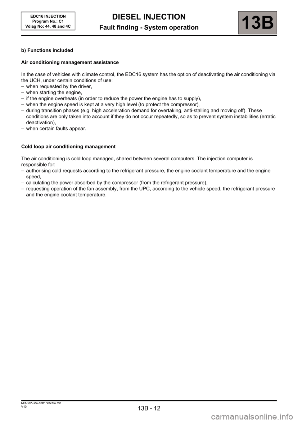
b) Functions included
Air conditioning management assistance
In the case of vehicles with climate control, the EDC16 system has the option of deactivating the air conditioning via
the UCH, under certain conditions of use:
– when requested by the driver,
– when starting the engine,
– if the engine overheats (in order to reduce the power the engine has to supply),
– when the engine speed is kept at a very high level (to protect the compressor),
– during transition phases (e.g. high acceleration demand for overtaking, anti-stalling and moving off). These
conditions are only taken into account if they do not occur repeatedly, so as to prevent system instabilities (erratic
deactivation),
– when certain faults appear.
Cold loop air conditioning management
The air conditioning is cold loop managed, shared between several computers. The injection computer is
responsible for:
– authorising cold requests according to the refrigerant pressure, the engine coolant temperature and the engine
speed,
– calculating the power absorbed by the compressor (from the refrigerant pressure),
– requesting operation of the fan assembly, from the UPC, according to the vehicle speed, the refrigerant pressure
and the engine coolant temperature.
Page 14 of 236

13B - 14
DIESEL INJECTION
Fault finding - System operation13B
V10 MR-372-J84-13B150$094.mif
EDC16 INJECTION
Program No.: C1
Vdiag No: 44, 48 and 4C
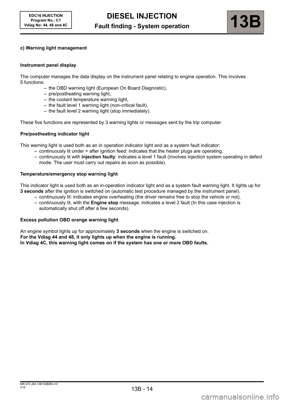
c) Warning light management
Instrument panel display
The computer manages the data display on the instrument panel relating to engine operation. This involves
5 functions:
– the OBD warning light (European On Board Diagnostic),
– pre/postheating warning light,
– the coolant temperature warning light,
– the fault level 1 warning light (non-critical fault),
– the fault level 2 warning light (stop immediately).
These five functions are represented by 3 warning lights or messages sent by the trip computer.
Pre/postheating indicator light
This warning light is used both as an in operation indicator light and as a system fault indicator:
– continuously lit under + after ignition feed: indicates that the heater plugs are operating,
– continuously lit with injection faulty: indicates a level 1 fault (involves injection system operating in defect
mode. The user must carry out repairs as soon as possible).
Temperature/emergency stop warning light
This indicator light is used both as an in-operation indicator light and as a system fault warning light. It lights up for
3 seconds after the ignition is switched on (automatic test procedure managed by the instrument panel).
– continuously lit: indicates engine overheating (the driver remains free to stop the vehicle or not),
– continuously lit, with the Engine stop message: indicates a level 2 fault (In this case injection is
automatically shut off after a few seconds).
Excess pollution OBD orange warning light
An engine symbol lights up for approximately 3 seconds when the engine is switched on.
For the Vdiag 44 and 48, it only lights up when the engine is running.
In Vdiag 4C, this warning light comes on if the system has one or more OBD faults.
Page 23 of 236

13B - 23
DIESEL INJECTION
Fault finding - Fault summary table13B
V10 MR-372-J84-13B150$235.mif
EDC16 INJECTION
Program No.: C1
Vdiag No.: 44, 48 and 4CDIESEL INJECTION
Fault finding - Fault summary table
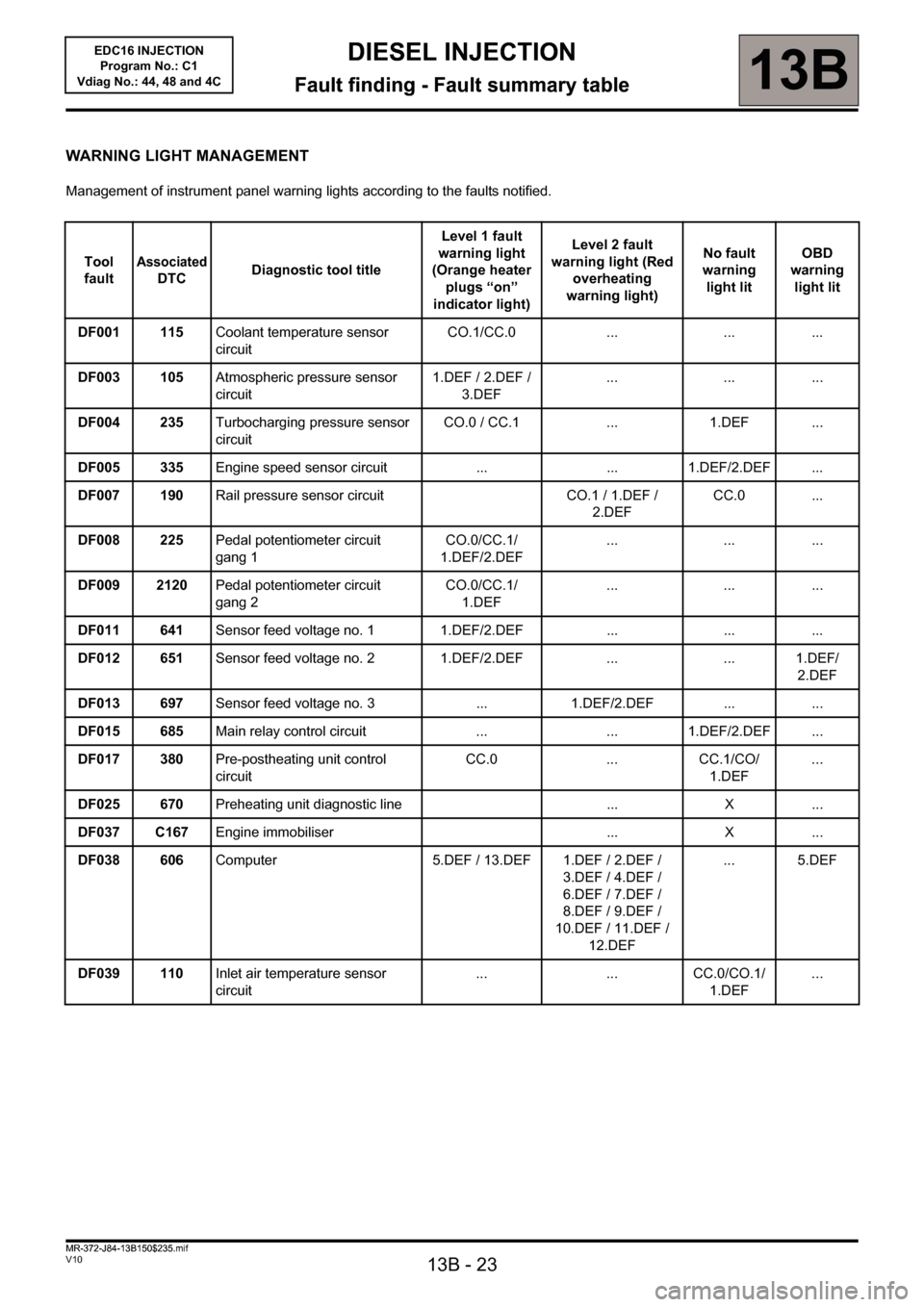
WARNING LIGHT MANAGEMENT
Management of instrument panel warning lights according to the faults notified.
Tool
fault
Associated
DTCDiagnostic tool titleLevel 1 fault
warning light
(Orange heater
plugs “on”
indicator light)Level 2 fault
warning light (Red
overheating
warning light)No fault
warning
light litOBD
warning
light lit
DF001 115Coolant temperature sensor
circuitCO.1/CC.0 ... ... ...
DF003 105Atmospheric pressure sensor
circuit1.DEF / 2.DEF /
3.DEF... ... ...
DF004 235Turbocharging pressure sensor
circuitCO.0 / CC.1 ... 1.DEF ...
DF005 335Engine speed sensor circuit ... ... 1.DEF/2.DEF ...
DF007 190Rail pressure sensor circuit CO.1 / 1.DEF /
2.DEFCC.0 ...
DF008 225Pedal potentiometer circuit
gang 1CO.0/CC.1/
1.DEF/2.DEF... ... ...
DF009 2120Pedal potentiometer circuit
gang 2CO.0/CC.1/
1.DEF... ... ...
DF011 641Sensor feed voltage no. 1 1.DEF/2.DEF ... ... ...
DF012 651Sensor feed voltage no. 2 1.DEF/2.DEF ... ... 1.DEF/
2.DEF
DF013 697Sensor feed voltage no. 3 ... 1.DEF/2.DEF ... ...
DF015 685Main relay control circuit ... ... 1.DEF/2.DEF ...
DF017 380Pre-postheating unit control
circuitCC.0 ... CC.1/CO/
1.DEF...
DF025 670Preheating unit diagnostic line ... X ...
DF037 C167Engine immobiliser ... X ...
DF038 606Computer 5.DEF / 13.DEF 1.DEF / 2.DEF /
3.DEF / 4.DEF /
6.DEF / 7.DEF /
8.DEF / 9.DEF /
10.DEF / 11.DEF /
12.DEF... 5.DEF
DF039 110Inlet air temperature sensor
circuit... ... CC.0/CO.1/
1.DEF...
MR-372-J84-13B150$235.mif
Page 26 of 236

13B-26
DIESEL INJECTION
Fault finding - Interpretation of faults13B
V10 MR-372-J84-13B150$282.mif
EDC16 INJECTION
Program No.: C1
Vdiag No.: 44, 48 and 4CDIESEL INJECTION
Fault finding - Interpretation of faults
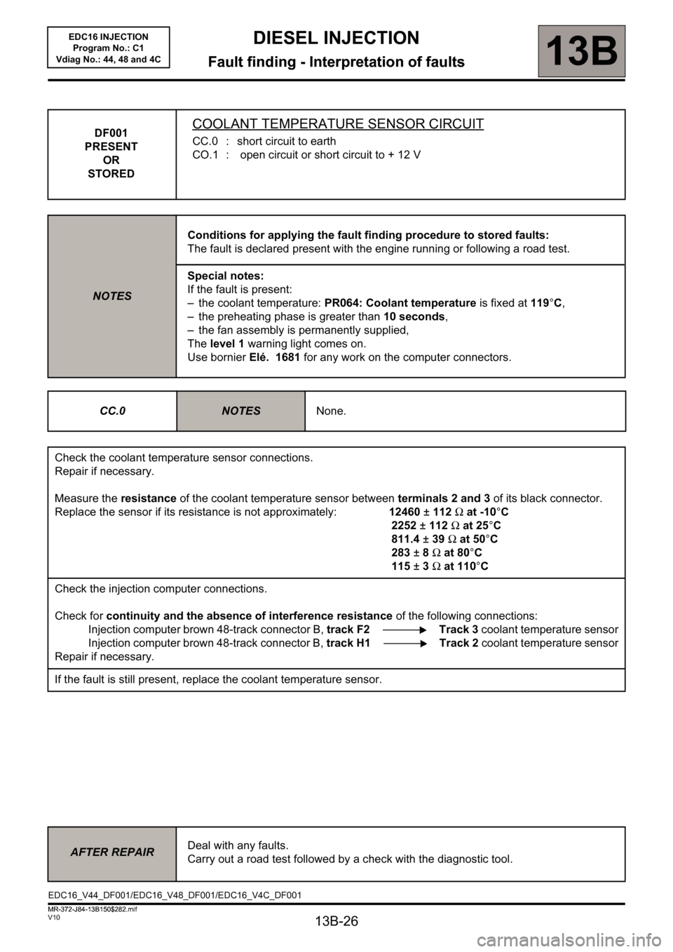
DF001
PRESENT
OR
STOREDCOOLANT TEMPERATURE SENSOR CIRCUIT
CC.0 : short circuit to earth
CO.1 : open circuit or short circuit to + 12 V
NOTESConditions for applying the fault finding procedure to stored faults:
The fault is declared present with the engine running or following a road test.
Special notes:
If the fault is present:
– the coolant temperature: PR064: Coolant temperature is fixed at 119°C,
– the preheating phase is greater than 10 seconds,
– the fan assembly is permanently supplied,
The level 1 warning light comes on.
Use bornier Elé. 1681 for any work on the computer connectors.
CC.0
NOTESNone.
Check the coolant temperature sensor connections.
Repair if necessary.
Measure the resistance of the coolant temperature sensor between terminals 2 and 3 of its black connector.
Replace the sensor if its resistance is not approximately: 12460±112Ω at -10°C
2252±112Ω at 25°C
811.4±39Ω at 50°C
283±8Ω at 80°C
115±3Ω at 110°C
Check the injection computer connections.
Check for continuity and the absence of interference resistance of the following connections:
Injection computer brown 48-track connector B, track F2 Track 3 coolant temperature sensor
Injection computer brown 48-track connector B, track H1 Track 2 coolant temperature sensor
Repair if necessary.
If the fault is still present, replace the coolant temperature sensor.
AFTER REPAIRDeal with any faults.
Carry out a road test followed by a check with the diagnostic tool.
EDC16_V44_DF001/EDC16_V48_DF001/EDC16_V4C_DF001
MR-372-J84-13B150$282.mif