charging RENAULT SCENIC 2011 J95 / 3.G Engine And Peripherals EDC16 Injection Workshop Manual
[x] Cancel search | Manufacturer: RENAULT, Model Year: 2011, Model line: SCENIC, Model: RENAULT SCENIC 2011 J95 / 3.GPages: 236, PDF Size: 1.32 MB
Page 9 of 236
13B - 9
DIESEL INJECTION
Fault finding - System operation13B
V10 MR-372-J84-13B150$094.mif
EDC16 INJECTION
Program No.: C1
Vdiag No: 44, 48 and 4CDIESEL INJECTION
Fault finding - System operation
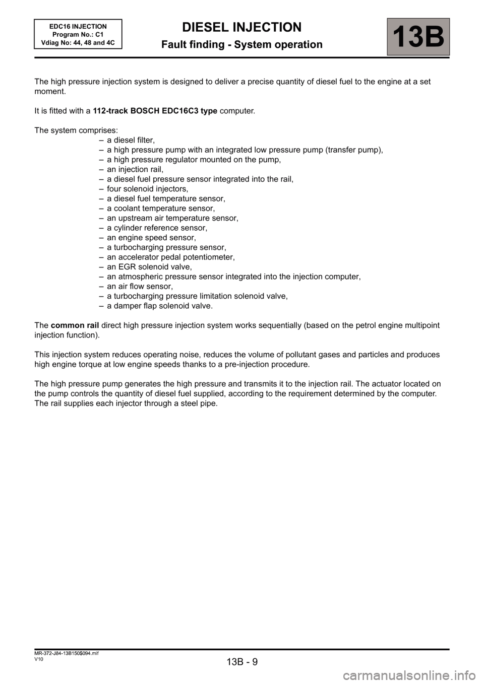
The high pressure injection system is designed to deliver a precise quantity of diesel fuel to the engine at a set
moment.
It is fitted with a 112-track BOSCH EDC16C3 type computer.
The system comprises:
– a diesel filter,
– a high pressure pump with an integrated low pressure pump (transfer pump),
– a high pressure regulator mounted on the pump,
– an injection rail,
– a diesel fuel pressure sensor integrated into the rail,
– four solenoid injectors,
– a diesel fuel temperature sensor,
– a coolant temperature sensor,
– an upstream air temperature sensor,
– a cylinder reference sensor,
– an engine speed sensor,
– a turbocharging pressure sensor,
– an accelerator pedal potentiometer,
– an EGR solenoid valve,
– an atmospheric pressure sensor integrated into the injection computer,
– an air flow sensor,
– a turbocharging pressure limitation solenoid valve,
– a damper flap solenoid valve.
The common rail direct high pressure injection system works sequentially (based on the petrol engine multipoint
injection function).
This injection system reduces operating noise, reduces the volume of pollutant gases and particles and produces
high engine torque at low engine speeds thanks to a pre-injection procedure.
The high pressure pump generates the high pressure and transmits it to the injection rail. The actuator located on
the pump controls the quantity of diesel fuel supplied, according to the requirement determined by the computer.
The rail supplies each injector through a steel pipe.
MR-372-J84-13B150$094.mif
Page 10 of 236
13B - 10
DIESEL INJECTION
Fault finding - System operation13B
V10 MR-372-J84-13B150$094.mif
EDC16 INJECTION
Program No.: C1
Vdiag No: 44, 48 and 4C
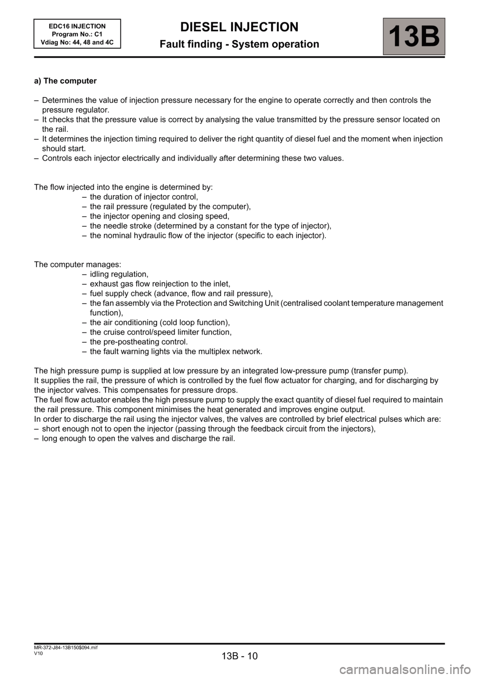
a) The computer
– Determines the value of injection pressure necessary for the engine to operate correctly and then controls the
pressure regulator.
– It checks that the pressure value is correct by analysing the value transmitted by the pressure sensor located on
the rail.
– It determines the injection timing required to deliver the right quantity of diesel fuel and the moment when injection
should start.
– Controls each injector electrically and individually after determining these two values.
The flow injected into the engine is determined by:
– the duration of injector control,
– the rail pressure (regulated by the computer),
– the injector opening and closing speed,
– the needle stroke (determined by a constant for the type of injector),
– the nominal hydraulic flow of the injector (specific to each injector).
The computer manages:
– idling regulation,
– exhaust gas flow reinjection to the inlet,
– fuel supply check (advance, flow and rail pressure),
– the fan assembly via the Protection and Switching Unit (centralised coolant temperature management
function),
– the air conditioning (cold loop function),
– the cruise control/speed limiter function,
– the pre-postheating control.
– the fault warning lights via the multiplex network.
The high pressure pump is supplied at low pressure by an integrated low-pressure pump (transfer pump).
It supplies the rail, the pressure of which is controlled by the fuel flow actuator for charging, and for discharging by
the injector valves. This compensates for pressure drops.
The fuel flow actuator enables the high pressure pump to supply the exact quantity of diesel fuel required to maintain
the rail pressure. This component minimises the heat generated and improves engine output.
In order to discharge the rail using the injector valves, the valves are controlled by brief electrical pulses which are:
– short enough not to open the injector (passing through the feedback circuit from the injectors),
– long enough to open the valves and discharge the rail.
Page 15 of 236
13B - 15
DIESEL INJECTION
Fault finding - System operation13B
V10 MR-372-J84-13B150$094.mif
EDC16 INJECTION
Program No.: C1
Vdiag No: 44, 48 and 4C
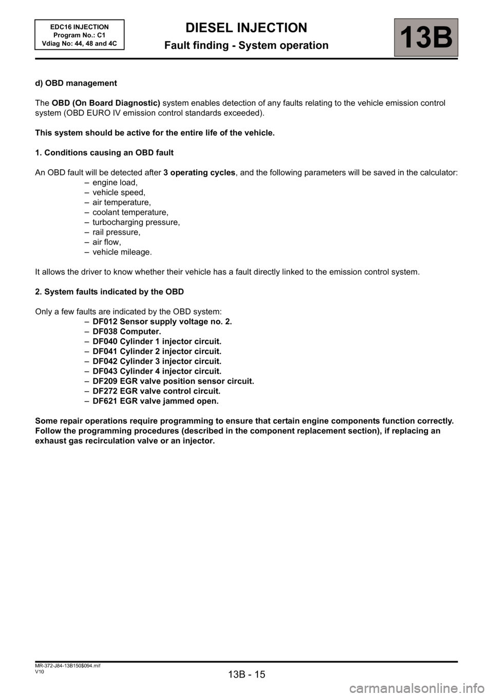
d) OBD management
The OBD (On Board Diagnostic) system enables detection of any faults relating to the vehicle emission control
system (OBD EURO IV emission control standards exceeded).
This system should be active for the entire life of the vehicle.
1. Conditions causing an OBD fault
An OBD fault will be detected after 3 operating cycles, and the following parameters will be saved in the calculator:
– engine load,
– vehicle speed,
– air temperature,
– coolant temperature,
– turbocharging pressure,
– rail pressure,
–air flow,
– vehicle mileage.
It allows the driver to know whether their vehicle has a fault directly linked to the emission control system.
2. System faults indicated by the OBD
Only a few faults are indicated by the OBD system:
–DF012 Sensor supply voltage no. 2.
–DF038 Computer.
–DF040 Cylinder 1 injector circuit.
–DF041 Cylinder 2 injector circuit.
–DF042 Cylinder 3 injector circuit.
–DF043 Cylinder 4 injector circuit.
–DF209 EGR valve position sensor circuit.
–DF272 EGR valve control circuit.
–DF621 EGR valve jammed open.
Some repair operations require programming to ensure that certain engine components function correctly.
Follow the programming procedures (described in the component replacement section), if replacing an
exhaust gas recirculation valve or an injector.
Page 18 of 236
13B - 18
DIESEL INJECTION
Fault finding - Allocation of computer tracks13B
V10 MR-372-J84-13B150$141.mif
EDC16 INJECTION
Program No.: C1
Vdiag No: 44, 48 and 4C
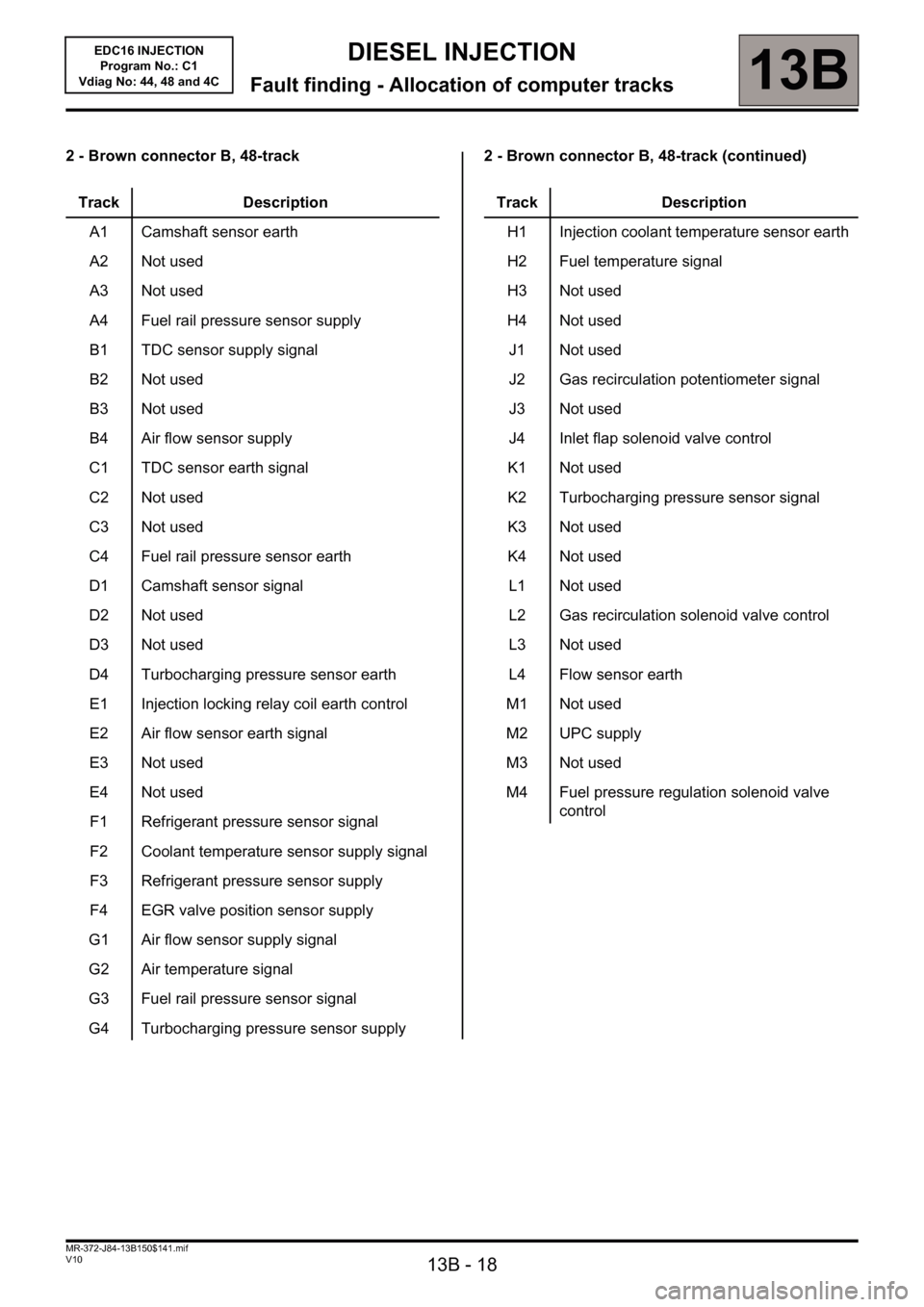
2 - Brown connector B, 48-track 2 - Brown connector B, 48-track (continued)
Track Description
A1 Camshaft sensor earth
A2 Not used
A3 Not used
A4 Fuel rail pressure sensor supply
B1 TDC sensor supply signal
B2 Not used
B3 Not used
B4 Air flow sensor supply
C1 TDC sensor earth signal
C2 Not used
C3 Not used
C4 Fuel rail pressure sensor earth
D1 Camshaft sensor signal
D2 Not used
D3 Not used
D4 Turbocharging pressure sensor earth
E1 Injection locking relay coil earth control
E2 Air flow sensor earth signal
E3 Not used
E4 Not used
F1 Refrigerant pressure sensor signal
F2 Coolant temperature sensor supply signal
F3 Refrigerant pressure sensor supply
F4 EGR valve position sensor supply
G1 Air flow sensor supply signal
G2 Air temperature signal
G3 Fuel rail pressure sensor signal
G4 Turbocharging pressure sensor supply
Track Description
H1 Injection coolant temperature sensor earth
H2 Fuel temperature signal
H3 Not used
H4 Not used
J1 Not used
J2 Gas recirculation potentiometer signal
J3 Not used
J4 Inlet flap solenoid valve control
K1 Not used
K2 Turbocharging pressure sensor signal
K3 Not used
K4 Not used
L1 Not used
L2 Gas recirculation solenoid valve control
L3 Not used
L4 Flow sensor earth
M1 Not used
M2 UPC supply
M3 Not used
M4 Fuel pressure regulation solenoid valve
control
Page 19 of 236
13B - 19
DIESEL INJECTION
Fault finding - Allocation of computer tracks13B
V10 MR-372-J84-13B150$141.mif
EDC16 INJECTION
Program No.: C1
Vdiag No: 44, 48 and 4C
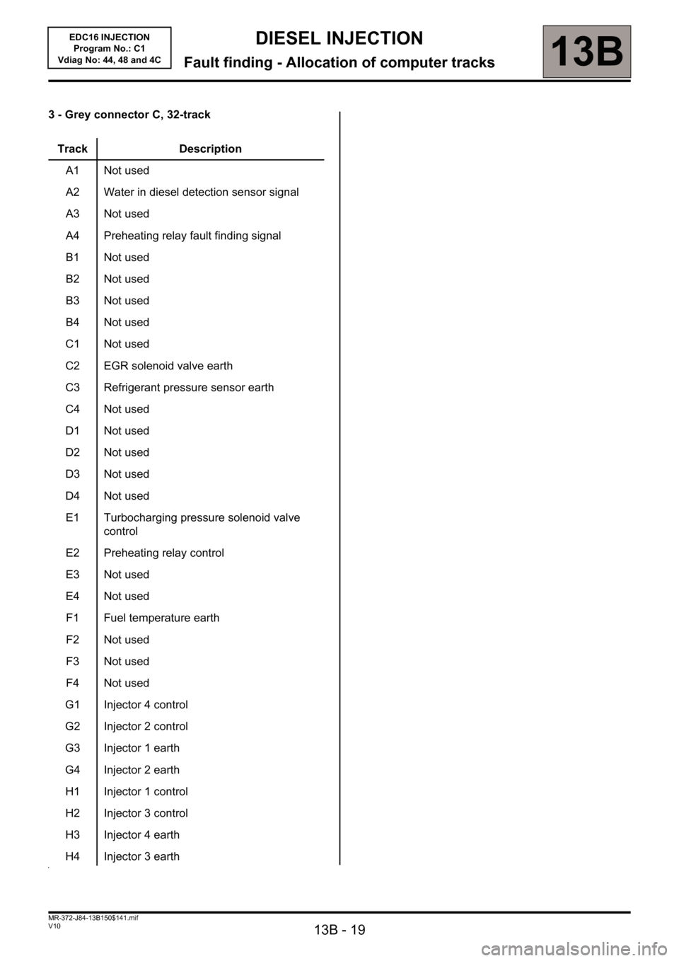
3 - Grey connector C, 32-track
Track Description
A1 Not used
A2 Water in diesel detection sensor signal
A3 Not used
A4 Preheating relay fault finding signal
B1 Not used
B2 Not used
B3 Not used
B4 Not used
C1 Not used
C2 EGR solenoid valve earth
C3 Refrigerant pressure sensor earth
C4 Not used
D1 Not used
D2 Not used
D3 Not used
D4 Not used
E1 Turbocharging pressure solenoid valve
control
E2 Preheating relay control
E3 Not used
E4 Not used
F1 Fuel temperature earth
F2 Not used
F3 Not used
F4 Not used
G1 Injector 4 control
G2 Injector 2 control
G3 Injector 1 earth
G4 Injector 2 earth
H1 Injector 1 control
H2 Injector 3 control
H3 Injector 4 earth
H4 Injector 3 earth
Page 23 of 236
13B - 23
DIESEL INJECTION
Fault finding - Fault summary table13B
V10 MR-372-J84-13B150$235.mif
EDC16 INJECTION
Program No.: C1
Vdiag No.: 44, 48 and 4CDIESEL INJECTION
Fault finding - Fault summary table
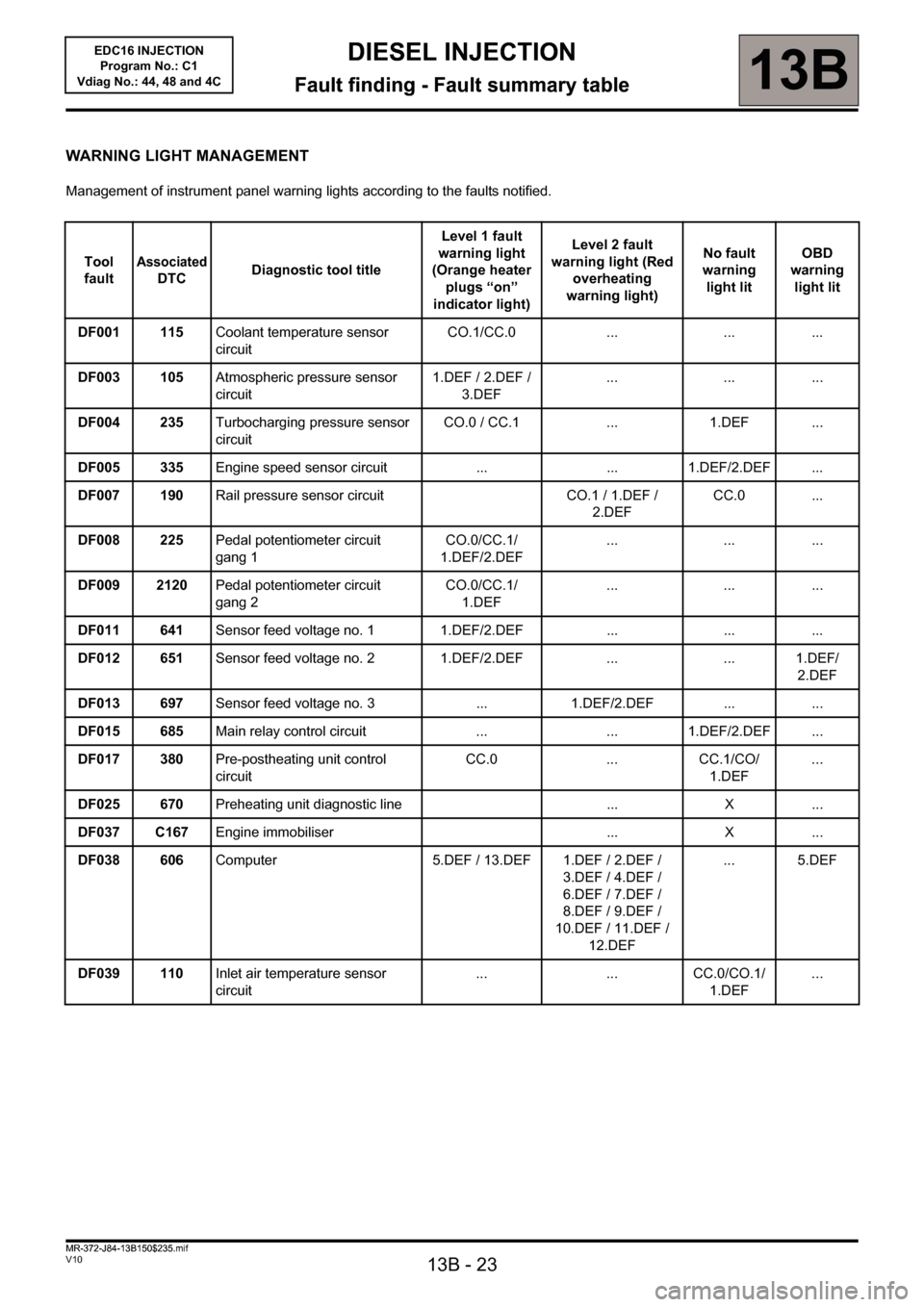
WARNING LIGHT MANAGEMENT
Management of instrument panel warning lights according to the faults notified.
Tool
fault
Associated
DTCDiagnostic tool titleLevel 1 fault
warning light
(Orange heater
plugs “on”
indicator light)Level 2 fault
warning light (Red
overheating
warning light)No fault
warning
light litOBD
warning
light lit
DF001 115Coolant temperature sensor
circuitCO.1/CC.0 ... ... ...
DF003 105Atmospheric pressure sensor
circuit1.DEF / 2.DEF /
3.DEF... ... ...
DF004 235Turbocharging pressure sensor
circuitCO.0 / CC.1 ... 1.DEF ...
DF005 335Engine speed sensor circuit ... ... 1.DEF/2.DEF ...
DF007 190Rail pressure sensor circuit CO.1 / 1.DEF /
2.DEFCC.0 ...
DF008 225Pedal potentiometer circuit
gang 1CO.0/CC.1/
1.DEF/2.DEF... ... ...
DF009 2120Pedal potentiometer circuit
gang 2CO.0/CC.1/
1.DEF... ... ...
DF011 641Sensor feed voltage no. 1 1.DEF/2.DEF ... ... ...
DF012 651Sensor feed voltage no. 2 1.DEF/2.DEF ... ... 1.DEF/
2.DEF
DF013 697Sensor feed voltage no. 3 ... 1.DEF/2.DEF ... ...
DF015 685Main relay control circuit ... ... 1.DEF/2.DEF ...
DF017 380Pre-postheating unit control
circuitCC.0 ... CC.1/CO/
1.DEF...
DF025 670Preheating unit diagnostic line ... X ...
DF037 C167Engine immobiliser ... X ...
DF038 606Computer 5.DEF / 13.DEF 1.DEF / 2.DEF /
3.DEF / 4.DEF /
6.DEF / 7.DEF /
8.DEF / 9.DEF /
10.DEF / 11.DEF /
12.DEF... 5.DEF
DF039 110Inlet air temperature sensor
circuit... ... CC.0/CO.1/
1.DEF...
MR-372-J84-13B150$235.mif
Page 24 of 236
13B - 24
DIESEL INJECTION
Fault finding - Fault summary table13B
V10 MR-372-J84-13B150$235.mif
EDC16 INJECTION
Program No.: C1
Vdiag No.: 44, 48 and 4C
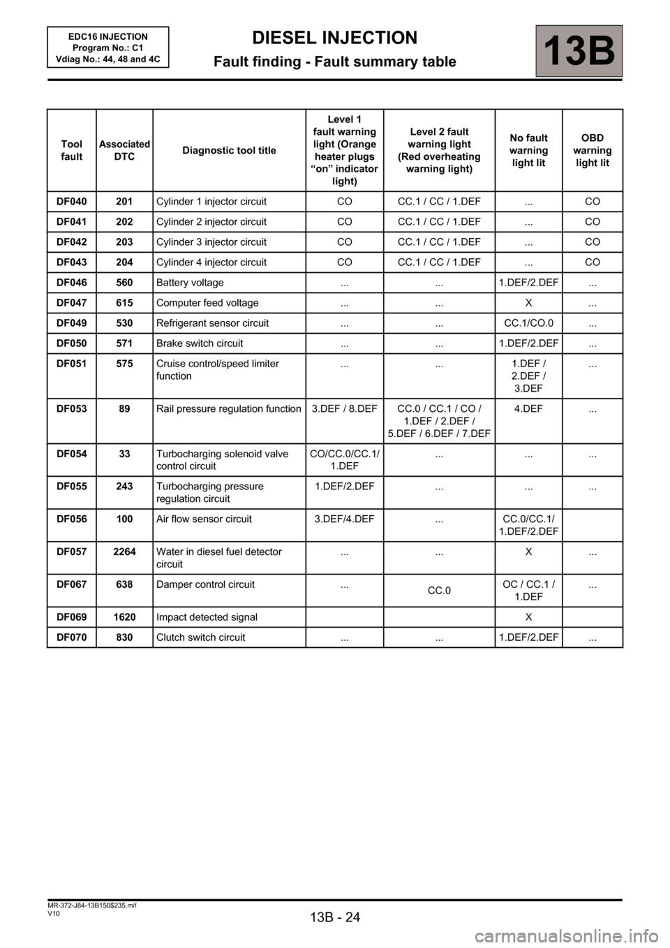
Tool
faultAssociated
DTCDiagnostic tool titleLevel 1
fault warning
light (Orange
heater plugs
“on” indicator
light)Level 2 fault
warning light
(Red overheating
warning light)No fault
warning
light litOBD
warning
light lit
DF040 201Cylinder 1 injector circuit CO CC.1 / CC / 1.DEF ... CO
DF041 202Cylinder 2 injector circuit CO CC.1 / CC / 1.DEF ... CO
DF042 203Cylinder 3 injector circuit CO CC.1 / CC / 1.DEF ... CO
DF043 204Cylinder 4 injector circuit CO CC.1 / CC / 1.DEF ... CO
DF046 560Battery voltage ... ... 1.DEF/2.DEF ...
DF047 615Computer feed voltage ... ... X ...
DF049 530Refrigerant sensor circuit ... ... CC.1/CO.0 ...
DF050 571Brake switch circuit ... ... 1.DEF/2.DEF ...
DF051 575Cruise control/speed limiter
function... ... 1.DEF /
2.DEF /
3.DEF...
DF053 89Rail pressure regulation function 3.DEF / 8.DEF CC.0 / CC.1 / CO /
1.DEF / 2.DEF /
5.DEF / 6.DEF / 7.DEF4.DEF ...
DF054 33Turbocharging solenoid valve
control circuitCO/CC.0/CC.1/
1.DEF... ... ...
DF055 243Turbocharging pressure
regulation circuit1.DEF/2.DEF ... ... ...
DF056 100Air flow sensor circuit 3.DEF/4.DEF ... CC.0/CC.1/
1.DEF/2.DEF
DF057 2264Water in diesel fuel detector
circuit... ... X ...
DF067 638Damper control circuit ...
CC.0OC / CC.1 /
1.DEF...
DF069 1620Impact detected signal X
DF070 830Clutch switch circuit ... ... 1.DEF/2.DEF ...
Page 28 of 236
13B-28
DIESEL INJECTION
Fault finding - Interpretation of faults13B
V10 MR-372-J84-13B150$282.mif
EDC16 INJECTION
Program No.: C1
Vdiag No.: 44, 48 and 4C
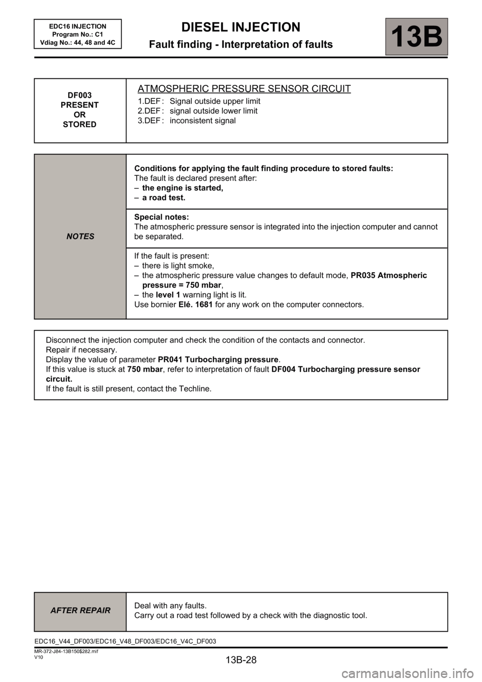
DF003
PRESENT
OR
STOREDATMOSPHERIC PRESSURE SENSOR CIRCUIT
1.DEF : Signal outside upper limit
2.DEF : signal outside lower limit
3.DEF : inconsistent signal
NOTESConditions for applying the fault finding procedure to stored faults:
The fault is declared present after:
–the engine is started,
–a road test.
Special notes:
The atmospheric pressure sensor is integrated into the injection computer and cannot
be separated.
If the fault is present:
– there is light smoke,
– the atmospheric pressure value changes to default mode, PR035 Atmospheric
pressure = 750 mbar,
–the level 1 warning light is lit.
Use bornier Elé. 1681 for any work on the computer connectors.
Disconnect the injection computer and check the condition of the contacts and connector.
Repair if necessary.
Display the value of parameter PR041 Turbocharging pressure.
If this value is stuck at 750 mbar, refer to interpretation of fault DF004 Turbocharging pressure sensor
circuit.
If the fault is still present, contact the Techline.
AFTER REPAIRDeal with any faults.
Carry out a road test followed by a check with the diagnostic tool.
EDC16_V44_DF003/EDC16_V48_DF003/EDC16_V4C_DF003
Page 29 of 236
13B-29
DIESEL INJECTION
Fault finding - Interpretation of faults13B
V10 MR-372-J84-13B150$282.mif
EDC16 INJECTION
Program No.: C1
Vdiag No.: 44, 48 and 4C
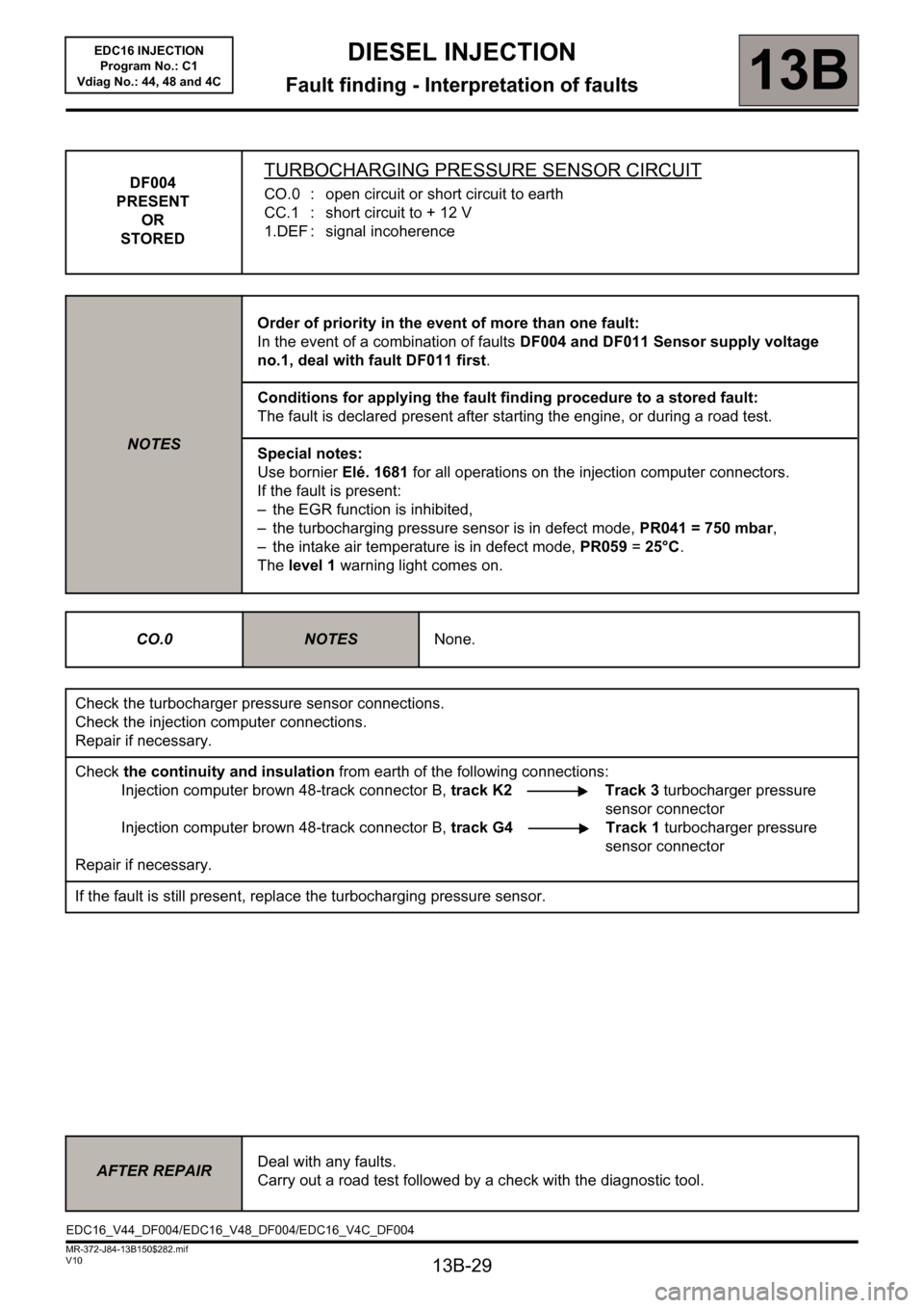
DF004
PRESENT
OR
STOREDTURBOCHARGING PRESSURE SENSOR CIRCUIT
CO.0 : open circuit or short circuit to earth
CC.1 : short circuit to + 12 V
1.DEF : signal incoherence
NOTESOrder of priority in the event of more than one fault:
In the event of a combination of faults DF004 and DF011 Sensor supply voltage
no.1, deal with fault DF011 first.
Conditions for applying the fault finding procedure to a stored fault:
The fault is declared present after starting the engine, or during a road test.
Special notes:
Use bornier Elé. 1681 for all operations on the injection computer connectors.
If the fault is present:
– the EGR function is inhibited,
– the turbocharging pressure sensor is in defect mode, PR041 = 750 mbar,
– the intake air temperature is in defect mode, PR059 = 25°C.
The level 1 warning light comes on.
CO.0
NOTESNone.
Check the turbocharger pressure sensor connections.
Check the injection computer connections.
Repair if necessary.
Check the continuity and insulation from earth of the following connections:
Injection computer brown 48-track connector B, track K2 Track 3 turbocharger pressure
sensor connector
Injection computer brown 48-track connector B, track G4 Track 1 turbocharger pressure
sensor connector
Repair if necessary.
If the fault is still present, replace the turbocharging pressure sensor.
AFTER REPAIRDeal with any faults.
Carry out a road test followed by a check with the diagnostic tool.
EDC16_V44_DF004/EDC16_V48_DF004/EDC16_V4C_DF004
Page 30 of 236
13B-30
DIESEL INJECTION
Fault finding - Interpretation of faults13B
V10 MR-372-J84-13B150$282.mif
EDC16 INJECTION
Program No.: C1
Vdiag No.: 44, 48 and 4C
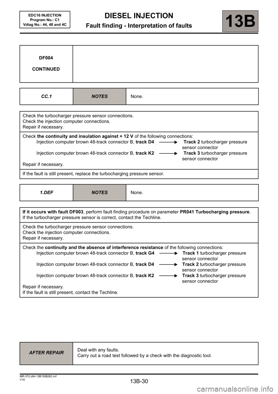
DF004
CONTINUED
CC.1
NOTESNone.
Check the turbocharger pressure sensor connections.
Check the injection computer connections.
Repair if necessary.
Check the continuity and insulation against + 12 V of the following connections:
Injection computer brown 48-track connector B, track D4 Track 2 turbocharger pressure
sensor connector
Injection computer brown 48-track connector B, track K2 Track 3 turbocharger pressure
sensor connector
Repair if necessary.
If the fault is still present, replace the turbocharging pressure sensor.
1.DEF
NOTESNone.
If it occurs with fault DF003, perform fault finding procedure on parameter PR041 Turbocharging pressure.
If the turbocharger pressure sensor is correct, contact the Techline.
Check the turbocharger pressure sensor connections.
Check the injection computer connections.
Repair if necessary.
Check the continuity and the absence of interference resistance of the following connections:
Injection computer brown 48-track connector B, track G4 Track 1 turbocharger pressure
sensor connector
Injection computer brown 48-track connector B, track D4 Track 2 turbocharger pressure
sensor connector
Injection computer brown 48-track connector B, track K2 Track 3 turbocharger pressure
sensor connector
Repair if necessary.
If the fault is still present, contact the Techline.
AFTER REPAIRDeal with any faults.
Carry out a road test followed by a check with the diagnostic tool.