diagram RENAULT SCENIC 2011 J95 / 3.G Engine And Peripherals EDC16 Injection Workshop Manual
[x] Cancel search | Manufacturer: RENAULT, Model Year: 2011, Model line: SCENIC, Model: RENAULT SCENIC 2011 J95 / 3.GPages: 236, PDF Size: 1.32 MB
Page 2 of 236
13B - 2
DIESEL INJECTION
Fault finding - Introduction13B
V10 MR-372-J84-13B150$047.mif
113B
EDC16 INJECTION
Program No.: C1
Vdiag No.: 44, 48 and 4CDIESEL INJECTION
Fault finding - Introduction
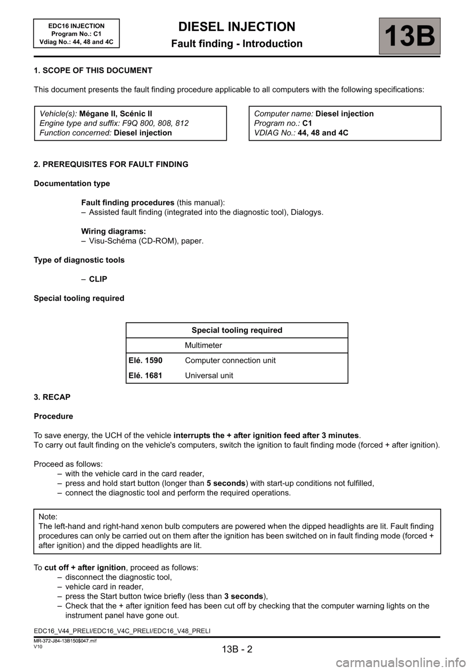
1. SCOPE OF THIS DOCUMENT
This document presents the fault finding procedure applicable to all computers with the following specifications:
2. PREREQUISITES FOR FAULT FINDING
Documentation type
Fault finding procedures (this manual):
– Assisted fault finding (integrated into the diagnostic tool), Dialogys.
Wiring diagrams:
– Visu-Schéma (CD-ROM), paper.
Type of diagnostic tools
–CLIP
Special tooling required
3. RECAP
Procedure
To save energy, the UCH of the vehicle interrupts the + after ignition feed after 3 minutes.
To carry out fault finding on the vehicle's computers, switch the ignition to fault finding mode (forced + after ignition).
Proceed as follows:
– with the vehicle card in the card reader,
– press and hold start button (longer than 5 seconds) with start-up conditions not fulfilled,
– connect the diagnostic tool and perform the required operations.
To cut off + after ignition, proceed as follows:
– disconnect the diagnostic tool,
– vehicle card in reader,
– press the Start button twice briefly (less than 3 seconds),
– Check that the + after ignition feed has been cut off by checking that the computer warning lights on the
instrument panel have gone out. Vehicle(s): Mégane II, Scénic II
Engine type and suffix: F9Q 800, 808, 812
Function concerned: Diesel injectionComputer name: Diesel injection
Program no.: C1
VDIAG No.: 44, 48 and 4C
Special tooling required
Multimeter
Elé. 1590Computer connection unit
Elé. 1681Universal unit
Note:
The left-hand and right-hand xenon bulb computers are powered when the dipped headlights are lit. Fault finding
procedures can only be carried out on them after the ignition has been switched on in fault finding mode (forced +
after ignition) and the dipped headlights are lit.
EDC16_V44_PRELI/EDC16_V4C_PRELI/EDC16_V48_PRELI
MR-372-J84-13B150$047.mif
Page 59 of 236
13B-59
DIESEL INJECTION
Fault finding - Interpretation of faults13B
V10 MR-372-J84-13B150$329.mif
EDC16 INJECTION
Program No.: C1
Vdiag No.: 44, 48 and 4C
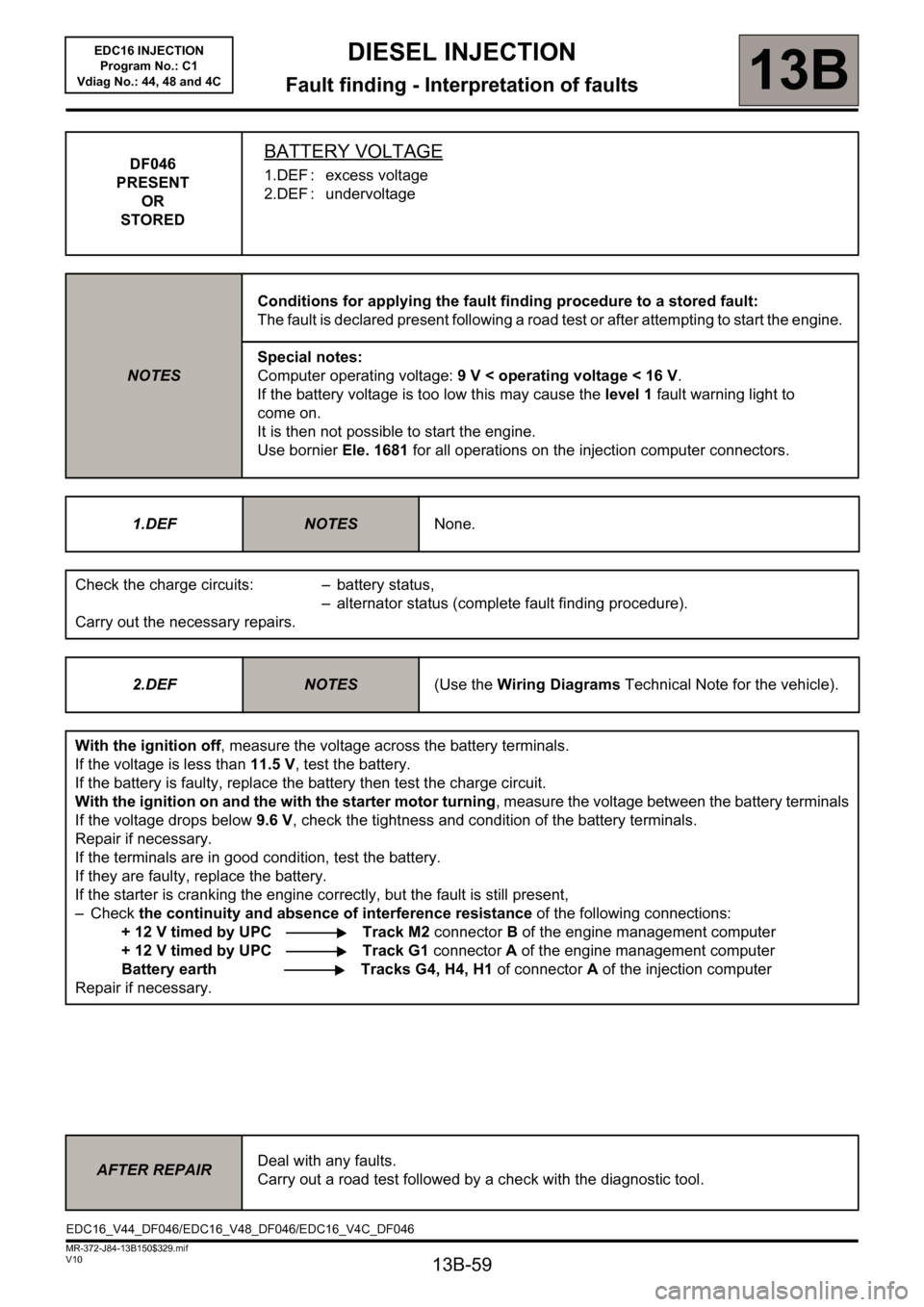
DF046
PRESENT
OR
STOREDBATTERY VOLTAGE
1.DEF : excess voltage
2.DEF : undervoltage
NOTESConditions for applying the fault finding procedure to a stored fault:
The fault is declared present following a road test or after attempting to start the engine.
Special notes:
Computer operating voltage: 9 V < operating voltage < 16 V.
If the battery voltage is too low this may cause the level 1 fault warning light to
come on.
It is then not possible to start the engine.
Use bornier Ele. 1681 for all operations on the injection computer connectors.
1.DEF
NOTESNone.
Check the charge circuits: – battery status,
– alternator status (complete fault finding procedure).
Carry out the necessary repairs.
2.DEF
NOTES(Use the Wiring Diagrams Technical Note for the vehicle).
With the ignition off, measure the voltage across the battery terminals.
If the voltage is less than 11.5 V, test the battery.
If the battery is faulty, replace the battery then test the charge circuit.
With the ignition on and the with the starter motor turning, measure the voltage between the battery terminals
If the voltage drops below 9.6 V, check the tightness and condition of the battery terminals.
Repair if necessary.
If the terminals are in good condition, test the battery.
If they are faulty, replace the battery.
If the starter is cranking the engine correctly, but the fault is still present,
–Check the continuity and absence of interference resistance of the following connections:
+ 12 V timed by UPC Track M2 connector B of the engine management computer
+ 12 V timed by UPC Track G1 connector A of the engine management computer
Battery earth Tracks G4, H4, H1 of connectorA of the injection computer
Repair if necessary.
AFTER REPAIRDeal with any faults.
Carry out a road test followed by a check with the diagnostic tool.
EDC16_V44_DF046/EDC16_V48_DF046/EDC16_V4C_DF046
Page 73 of 236
13B-73
DIESEL INJECTION
Fault finding - Interpretation of faults13B
V10 MR-372-J84-13B150$329.mif
EDC16 INJECTION
Program No.: C1
Vdiag No.: 44, 48 and 4C
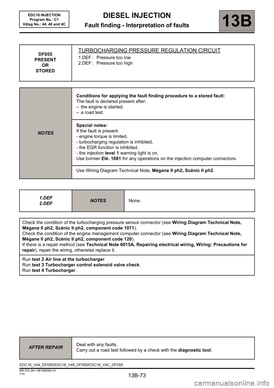
DF055
PRESENT
OR
STOREDTURBOCHARGING PRESSURE REGULATION CIRCUIT
1.DEF : Pressure too low
2.DEF : Pressure too high
NOTESConditions for applying the fault finding procedure to a stored fault:
The fault is declared present after:
– the engine is started,
– a road test.
Special notes:
If the fault is present:
- engine torque is limited,
- turbocharging regulation is inhibited,
- the EGR function is inhibited,
- the injection level 1 warning light is on.
Use bornier Elé. 1681 for any operations on the injection computer connectors.
Use Wiring Diagram Technical Note, Mégane II ph2, Scénic II ph2.
1.DEF
2.DEF
NOTESNone.
Check the condition of the turbocharging pressure sensor connector (see Wiring Diagram Technical Note,
Mégane II ph2, Scénic II ph2, component code 1071).
Check the condition of the engine management computer connector (see Wiring Diagram Technical Note,
Mégane II ph2, Scénic II ph2, component code 120).
If there is a repair method (see Technical Note 6015A, Repairing electrical wiring, Wiring: Precautions for
repair), repair the wiring, otherwise replace it.
Run test 2 Air line at the turbocharger.
Run test 3 Turbocharger control solenoid valve check.
Run test 4 Turbocharger.
AFTER REPAIRDeal with any faults.
Carry out a road test followed by a check with the diagnostic tool.
EDC16_V44_DF055/EDC16_V48_DF055/EDC16_V4C_DF055
Page 85 of 236
13B-85
DIESEL INJECTION
Fault finding - Interpretation of faults
13B
V10 MR-372-J84-13B150$376.mif
EDC16 INJECTION
Program No.: C1
Vdiag No.: 44, 48 and 4C
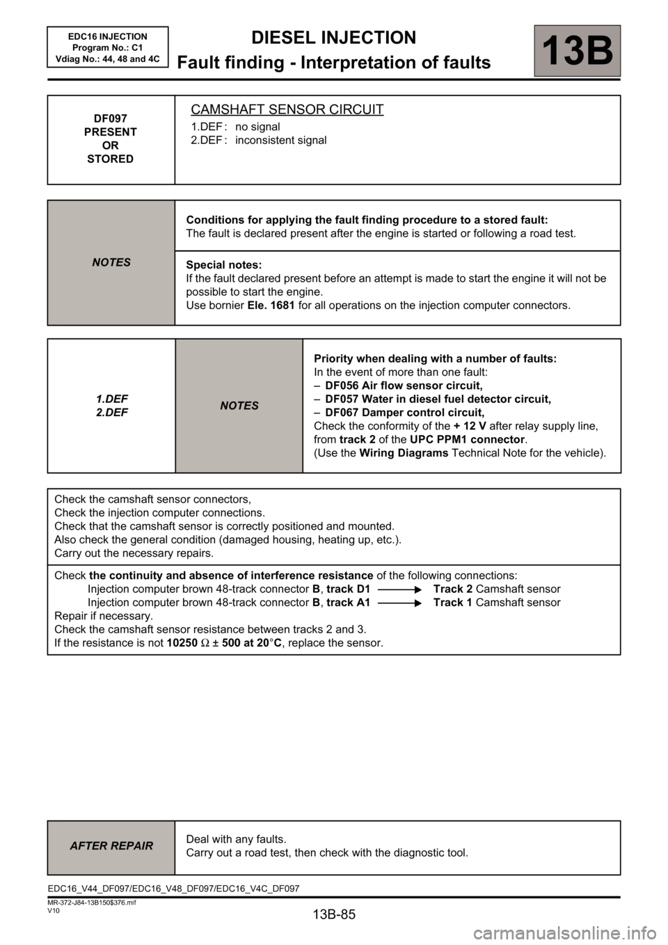
DF097
PRESENT
OR
STOREDCAMSHAFT SENSOR CIRCUIT
1.DEF : no signal
2.DEF : inconsistent signal
NOTESConditions for applying the fault finding procedure to a stored fault:
The fault is declared present after the engine is started or following a road test.
Special notes:
If the fault declared present before an attempt is made to start the engine it will not be
possible to start the engine.
Use bornier Ele. 1681 for all operations on the injection computer connectors.
1.DEF
2.DEF
NOTESPriority when dealing with a number of faults:
In the event of more than one fault:
–DF056 Air flow sensor circuit,
–DF057 Water in diesel fuel detector circuit,
–DF067 Damper control circuit,
Check the conformity of the + 12 V after relay supply line,
from track 2 of the UPC PPM1 connector.
(Use the Wiring Diagrams Technical Note for the vehicle).
Check the camshaft sensor connectors,
Check the injection computer connections.
Check that the camshaft sensor is correctly positioned and mounted.
Also check the general condition (damaged housing, heating up, etc.).
Carry out the necessary repairs.
Check the continuity and absence of interference resistance of the following connections:
Injection computer brown 48-track connector B, track D1 Track 2 Camshaft sensor
Injection computer brown 48-track connector B, track A1 Track 1 Camshaft sensor
Repair if necessary.
Check the camshaft sensor resistance between tracks 2 and 3.
If the resistance is not 10250Ω ±500 at 20°C, replace the sensor.
AFTER REPAIRDeal with any faults.
Carry out a road test, then check with the diagnostic tool.
EDC16_V44_DF097/EDC16_V48_DF097/EDC16_V4C_DF097
Page 194 of 236
13B - 194
DIESEL INJECTION
Fault finding - Interpretation of commands13B
V10 MR-372-J84-13B150$752.mif
EDC16 INJECTION
Program No.: C1
Vdiag No: 44, 48 and 4C
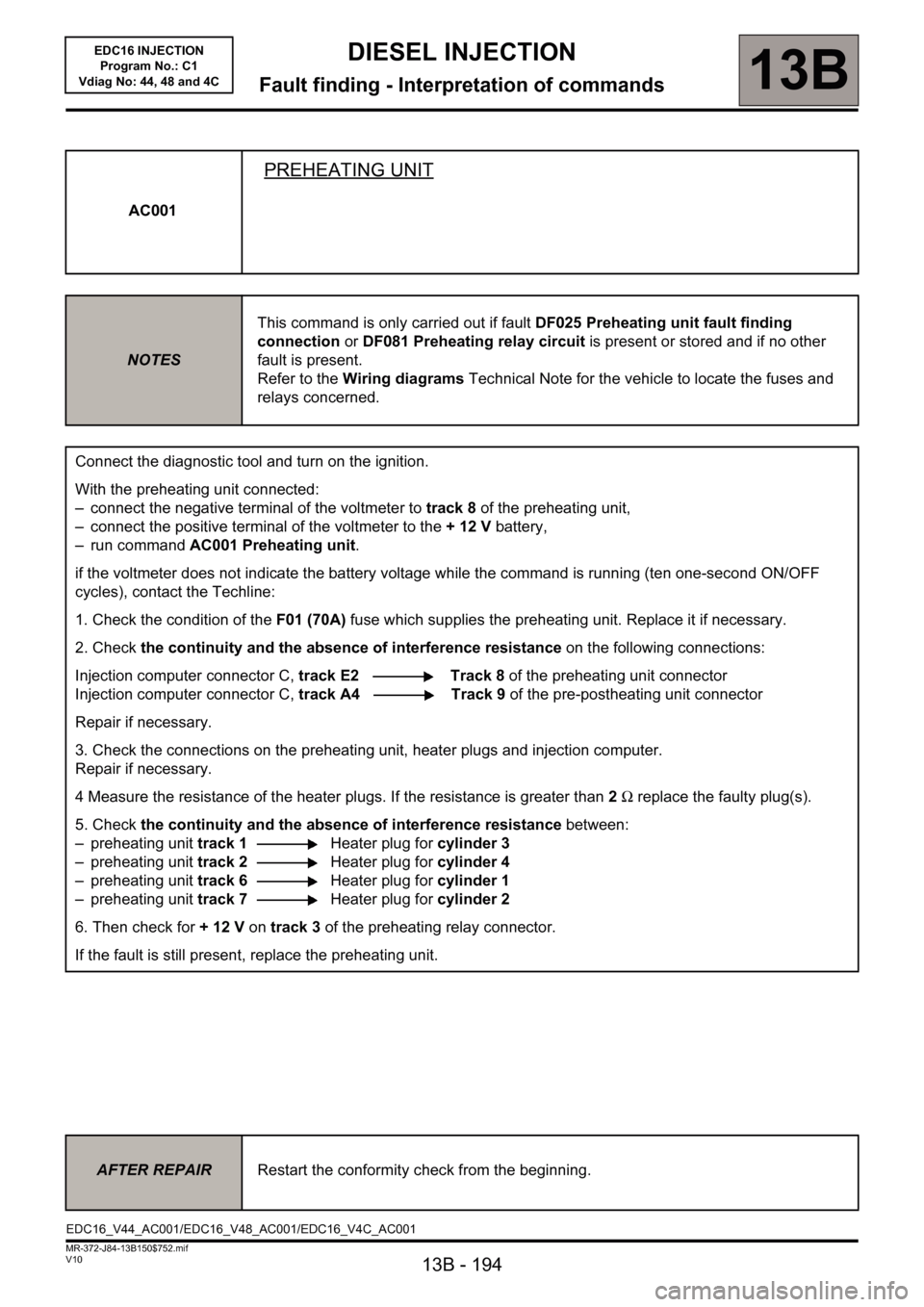
AC001
PREHEATING UNIT
NOTESThis command is only carried out if fault DF025 Preheating unit fault finding
connection or DF081 Preheating relay circuit is present or stored and if no other
fault is present.
Refer to the Wiring diagrams Technical Note for the vehicle to locate the fuses and
relays concerned.
Connect the diagnostic tool and turn on the ignition.
With the preheating unit connected:
– connect the negative terminal of the voltmeter to track 8 of the preheating unit,
– connect the positive terminal of the voltmeter to the + 12 V battery,
– run command AC001 Preheating unit.
if the voltmeter does not indicate the battery voltage while the command is running (ten one-second ON/OFF
cycles), contact the Techline:
1. Check the condition of theF01 (70A) fuse which supplies the preheating unit. Replace it if necessary.
2. Check the continuity and the absence of interference resistance on the following connections:
Injection computer connector C, track E2 Track 8 of the preheating unit connector
Injection computer connector C, track A4 Track 9 of the pre-postheating unit connector
Repair if necessary.
3. Check the connections on the preheating unit, heater plugs and injection computer.
Repair if necessary.
4 Measure the resistance of the heater plugs. If the resistance is greater than 2Ω replace the faulty plug(s).
5. Check the continuity and the absence of interference resistance between:
– preheating unit track 1Heater plug for cylinder 3
– preheating unit track 2Heater plug for cylinder 4
– preheating unit track 6Heater plug for cylinder 1
– preheating unit track 7Heater plug for cylinder 2
6. Then check for +12V on track 3 of the preheating relay connector.
If the fault is still present, replace the preheating unit.
AFTER REPAIRRestart the conformity check from the beginning.
EDC16_V44_AC001/EDC16_V48_AC001/EDC16_V4C_AC001
Page 204 of 236
13B-204
MR-372-J84-13B150$846.mif
V10
DIESEL INJECTION
Fault finding - Fault finding chart13B
ALP 1
CONTINUED
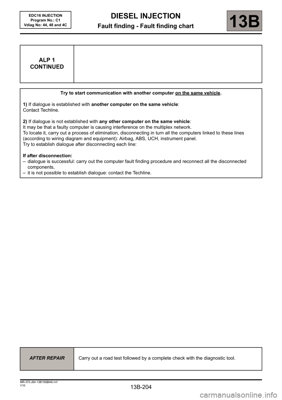
Try to start communication with another computer on the same vehicle.
1)If dialogue is established with another computer on the same vehicle:
Contact Techline.
2)If dialogue is not established with any other computer on the same vehicle:
It may be that a faulty computer is causing interference on the multiplex network.
To locate it, carry out a process of elimination, disconnecting in turn all the computers linked to these lines
(according to wiring diagram and equipment): Airbag, ABS, UCH, instrument panel.
Try to establish dialogue after disconnecting each line:
If after disconnection:
– dialogue is successful: carry out the computer fault finding procedure and reconnect all the disconnected
components,
– it is not possible to establish dialogue: contact the Techline.
AFTER REPAIRCarry out a road test followed by a complete check with the diagnostic tool.
EDC16 INJECTION
Program No.: C1
Vdiag No: 44, 48 and 4C
Page 220 of 236
13B-220
MR-372-J84-13B150$893.mif
V10
DIESEL INJECTION
Fault finding - Tests
EDC16 INJECTION
Program No.: C1
Vdiag No.: 44, 48 and 4C
13B
TEST 1
CONTINUED 2
Part C: Measuring fuel return flow
1 - Fitting the tool:
Only carry out this part if PR063 Fuel temperature is greater than 50°C (see step 2 of Part C of this test).
Remove the engine undertray
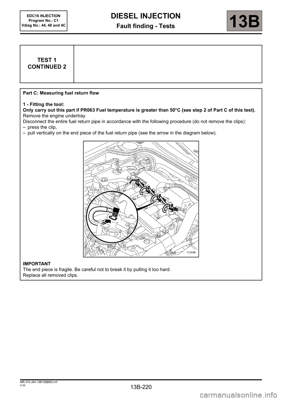
Disconnect the entire fuel return pipe in accordance with the following procedure (do not remove the clips):
– press the clip,
– pull vertically on the end piece of the fuel return pipe (see the arrow in the diagram below).
IMPORTANT
The end piece is fragile. Be careful not to break it by pulling it too hard.
Replace all removed clips.
Page 222 of 236
13B-222
MR-372-J84-13B150$893.mif
V10
DIESEL INJECTION
Fault finding - Tests
EDC16 INJECTION
Program No.: C1
Vdiag No.: 44, 48 and 4C
13B
TEST 1
CONTINUED 4
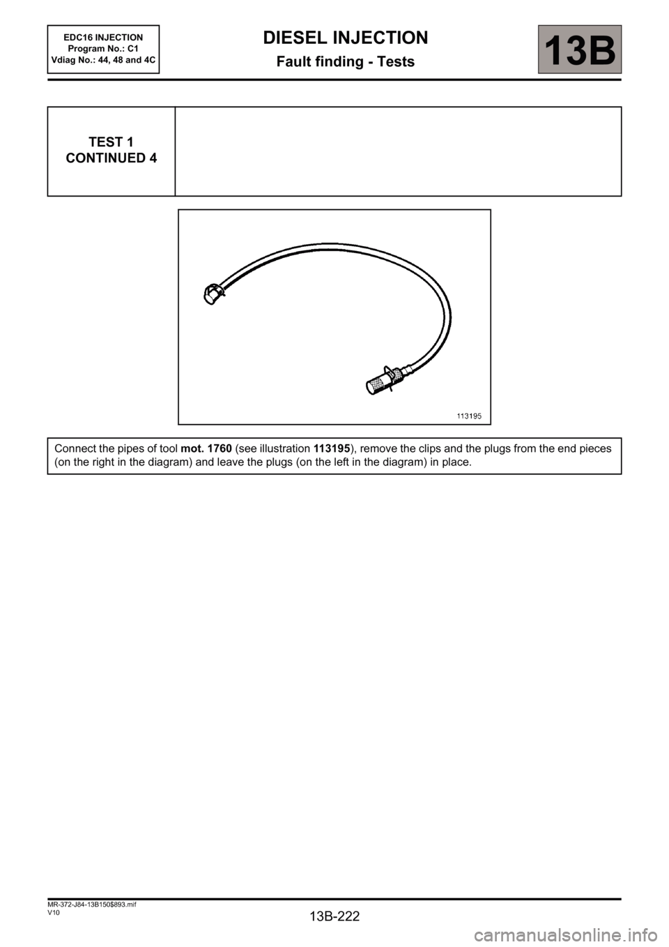
Connect the pipes of tool mot. 1760 (see illustration 113195), remove the clips and the plugs from the end pieces
(on the right in the diagram) and leave the plugs (on the left in the diagram) in place.