relay RENAULT SCENIC 2011 J95 / 3.G Engine And Peripherals EDC16 Injection Workshop Manual
[x] Cancel search | Manufacturer: RENAULT, Model Year: 2011, Model line: SCENIC, Model: RENAULT SCENIC 2011 J95 / 3.GPages: 236, PDF Size: 1.32 MB
Page 18 of 236
13B - 18
DIESEL INJECTION
Fault finding - Allocation of computer tracks13B
V10 MR-372-J84-13B150$141.mif
EDC16 INJECTION
Program No.: C1
Vdiag No: 44, 48 and 4C
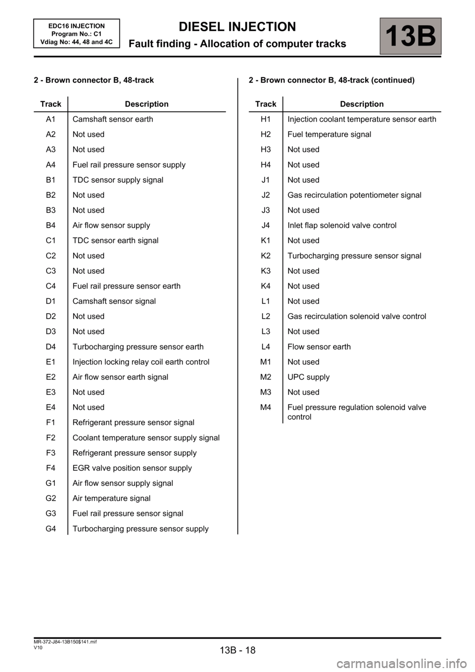
2 - Brown connector B, 48-track 2 - Brown connector B, 48-track (continued)
Track Description
A1 Camshaft sensor earth
A2 Not used
A3 Not used
A4 Fuel rail pressure sensor supply
B1 TDC sensor supply signal
B2 Not used
B3 Not used
B4 Air flow sensor supply
C1 TDC sensor earth signal
C2 Not used
C3 Not used
C4 Fuel rail pressure sensor earth
D1 Camshaft sensor signal
D2 Not used
D3 Not used
D4 Turbocharging pressure sensor earth
E1 Injection locking relay coil earth control
E2 Air flow sensor earth signal
E3 Not used
E4 Not used
F1 Refrigerant pressure sensor signal
F2 Coolant temperature sensor supply signal
F3 Refrigerant pressure sensor supply
F4 EGR valve position sensor supply
G1 Air flow sensor supply signal
G2 Air temperature signal
G3 Fuel rail pressure sensor signal
G4 Turbocharging pressure sensor supply
Track Description
H1 Injection coolant temperature sensor earth
H2 Fuel temperature signal
H3 Not used
H4 Not used
J1 Not used
J2 Gas recirculation potentiometer signal
J3 Not used
J4 Inlet flap solenoid valve control
K1 Not used
K2 Turbocharging pressure sensor signal
K3 Not used
K4 Not used
L1 Not used
L2 Gas recirculation solenoid valve control
L3 Not used
L4 Flow sensor earth
M1 Not used
M2 UPC supply
M3 Not used
M4 Fuel pressure regulation solenoid valve
control
Page 19 of 236
13B - 19
DIESEL INJECTION
Fault finding - Allocation of computer tracks13B
V10 MR-372-J84-13B150$141.mif
EDC16 INJECTION
Program No.: C1
Vdiag No: 44, 48 and 4C
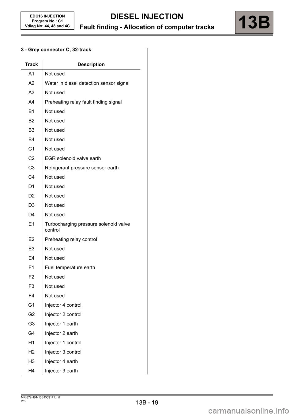
3 - Grey connector C, 32-track
Track Description
A1 Not used
A2 Water in diesel detection sensor signal
A3 Not used
A4 Preheating relay fault finding signal
B1 Not used
B2 Not used
B3 Not used
B4 Not used
C1 Not used
C2 EGR solenoid valve earth
C3 Refrigerant pressure sensor earth
C4 Not used
D1 Not used
D2 Not used
D3 Not used
D4 Not used
E1 Turbocharging pressure solenoid valve
control
E2 Preheating relay control
E3 Not used
E4 Not used
F1 Fuel temperature earth
F2 Not used
F3 Not used
F4 Not used
G1 Injector 4 control
G2 Injector 2 control
G3 Injector 1 earth
G4 Injector 2 earth
H1 Injector 1 control
H2 Injector 3 control
H3 Injector 4 earth
H4 Injector 3 earth
Page 23 of 236
13B - 23
DIESEL INJECTION
Fault finding - Fault summary table13B
V10 MR-372-J84-13B150$235.mif
EDC16 INJECTION
Program No.: C1
Vdiag No.: 44, 48 and 4CDIESEL INJECTION
Fault finding - Fault summary table
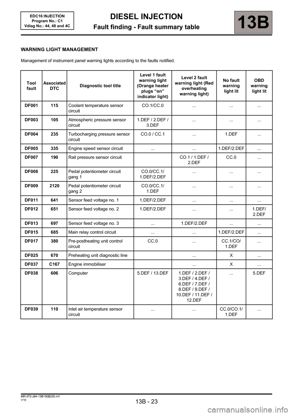
WARNING LIGHT MANAGEMENT
Management of instrument panel warning lights according to the faults notified.
Tool
fault
Associated
DTCDiagnostic tool titleLevel 1 fault
warning light
(Orange heater
plugs “on”
indicator light)Level 2 fault
warning light (Red
overheating
warning light)No fault
warning
light litOBD
warning
light lit
DF001 115Coolant temperature sensor
circuitCO.1/CC.0 ... ... ...
DF003 105Atmospheric pressure sensor
circuit1.DEF / 2.DEF /
3.DEF... ... ...
DF004 235Turbocharging pressure sensor
circuitCO.0 / CC.1 ... 1.DEF ...
DF005 335Engine speed sensor circuit ... ... 1.DEF/2.DEF ...
DF007 190Rail pressure sensor circuit CO.1 / 1.DEF /
2.DEFCC.0 ...
DF008 225Pedal potentiometer circuit
gang 1CO.0/CC.1/
1.DEF/2.DEF... ... ...
DF009 2120Pedal potentiometer circuit
gang 2CO.0/CC.1/
1.DEF... ... ...
DF011 641Sensor feed voltage no. 1 1.DEF/2.DEF ... ... ...
DF012 651Sensor feed voltage no. 2 1.DEF/2.DEF ... ... 1.DEF/
2.DEF
DF013 697Sensor feed voltage no. 3 ... 1.DEF/2.DEF ... ...
DF015 685Main relay control circuit ... ... 1.DEF/2.DEF ...
DF017 380Pre-postheating unit control
circuitCC.0 ... CC.1/CO/
1.DEF...
DF025 670Preheating unit diagnostic line ... X ...
DF037 C167Engine immobiliser ... X ...
DF038 606Computer 5.DEF / 13.DEF 1.DEF / 2.DEF /
3.DEF / 4.DEF /
6.DEF / 7.DEF /
8.DEF / 9.DEF /
10.DEF / 11.DEF /
12.DEF... 5.DEF
DF039 110Inlet air temperature sensor
circuit... ... CC.0/CO.1/
1.DEF...
MR-372-J84-13B150$235.mif
Page 45 of 236
13B-45
DIESEL INJECTION
Fault finding - Interpretation of faults13B
V10 MR-372-J84-13B150$282.mif
EDC16 INJECTION
Program No.: C1
Vdiag No.: 44, 48 and 4C
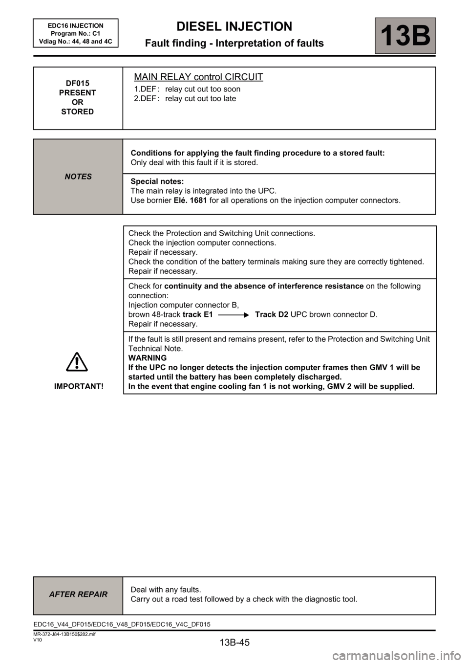
DF015
PRESENT
OR
STOREDMAIN RELAY control CIRCUIT
1.DEF : relay cut out too soon
2.DEF : relay cut out too late
NOTESConditions for applying the fault finding procedure to a stored fault:
Only deal with this fault if it is stored.
Special notes:
The main relay is integrated into the UPC.
Use bornier Elé. 1681 for all operations on the injection computer connectors.
Check the Protection and Switching Unit connections.
Check the injection computer connections.
Repair if necessary.
Check the condition of the battery terminals making sure they are correctly tightened.
Repair if necessary.
Check for continuity and the absence of interference resistance on the following
connection:
Injection computer connector B,
brown 48-track track E1 Track D2 UPC brown connector D.
Repair if necessary.
IMPORTANT!If the fault is still present and remains present, refer to the Protection and Switching Unit
Technical Note.
WARNING
If the UPC no longer detects the injection computer frames then GMV 1 will be
started until the battery has been completely discharged.
In the event that engine cooling fan 1 is not working, GMV 2 will be supplied.
AFTER REPAIRDeal with any faults.
Carry out a road test followed by a check with the diagnostic tool.
EDC16_V44_DF015/EDC16_V48_DF015/EDC16_V4C_DF015
Page 48 of 236
13B-48
DIESEL INJECTION
Fault finding - Interpretation of faults13B
V10 MR-372-J84-13B150$282.mif
EDC16 INJECTION
Program No.: C1
Vdiag No.: 44, 48 and 4C
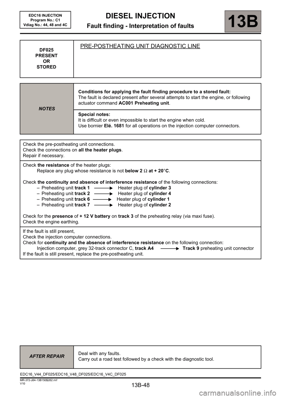
DF025
PRESENT
OR
STOREDPRE-POSTHEATING UNIT DIAGNOSTIC LINE
NOTESConditions for applying the fault finding procedure to a stored fault:
The fault is declared present after several attempts to start the engine, or following
actuator command AC001 Preheating unit.
Special notes:
It is difficult or even impossible to start the engine when cold.
Use bornier Elé. 1681 for all operations on the injection computer connectors.
Check the pre-postheating unit connections.
Check the connections on all the heater plugs.
Repair if necessary.
Check the resistance of the heater plugs:
Replace any plug whose resistance is not below 2Ω at + 20°C.
Check the continuity and absence of interference resistance of the following connections:
– Preheating unit track 1 Heater plug of cylinder 3
– Preheating unit track 2 Heater plug of cylinder 4
– Preheating unit track 6Heater plug of cylinder 1
– Preheating unit track 7 Heater plug of cylinder 2
Check for the presence of +12V battery on track 3 of the preheating relay (via maxi fuse).
Check the engine earthing.
If the fault is still present,
Check the injection computer connections.
Check for continuity and the absence of interference resistance on the following connection:
Injection computer, grey 32-track connector C, track A4 Track 9 preheating unit connector
If the fault is still present, replace the pre-postheating unit.
AFTER REPAIRDeal with any faults.
Carry out a road test followed by a check with the diagnostic tool.
EDC16_V44_DF025/EDC16_V48_DF025/EDC16_V4C_DF025
Page 60 of 236
13B-60
DIESEL INJECTION
Fault finding - Interpretation of faults13B
V10 MR-372-J84-13B150$329.mif
EDC16 INJECTION
Program No.: C1
Vdiag No.: 44, 48 and 4C
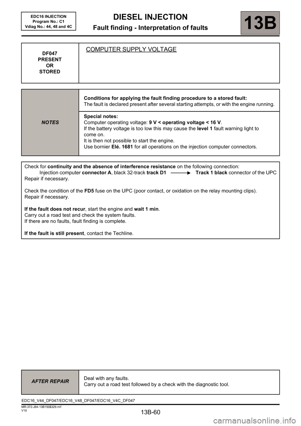
DF047
PRESENT
OR
STOREDCOMPUTER SUPPLY VOLTAGE
NOTESConditions for applying the fault finding procedure to a stored fault:
The fault is declared present after several starting attempts, or with the engine running.
Special notes:
Computer operating voltage: 9 V < operating voltage < 16 V.
If the battery voltage is too low this may cause the level 1 fault warning light to
come on.
It is then not possible to start the engine.
Use bornier Elé. 1681 for all operations on the injection computer connectors.
Check for continuity and the absence of interference resistance on the following connection:
Injection computer connector A, black 32-track track D1 Track 1 black connector of the UPC
Repair if necessary.
Check the condition of the FD5 fuse on the UPC (poor contact, or oxidation on the relay mounting clips).
Repair if necessary.
If the fault does not recur, start the engine and wait 1 min.
Carry out a road test and check the system faults.
If there are no faults, fault finding is complete.
If the fault is still present, contact the Techline.
AFTER REPAIRDeal with any faults.
Carry out a road test followed by a check with the diagnostic tool.
EDC16_V44_DF047/EDC16_V48_DF047/EDC16_V4C_DF047
Page 64 of 236
13B-64
DIESEL INJECTION
Fault finding - Interpretation of faults13B
V10 MR-372-J84-13B150$329.mif
EDC16 INJECTION
Program No.: C1
Vdiag No.: 44, 48 and 4C
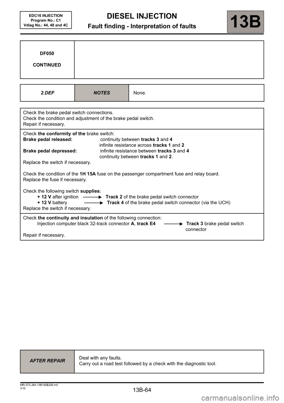
DF050
CONTINUED
2.DEF
NOTESNone.
Check the brake pedal switch connections.
Check the condition and adjustment of the brake pedal switch.
Repair if necessary.
Check the conformity of the brake switch:
Brake pedal released: continuity between tracks 3 and 4
infinite resistance across tracks 1 and 2
Brake pedal depressed: infinite resistance between tracks 3 and 4
continuity between tracks 1 and 2.
Replace the switch if necessary.
Check the condition of the 1H 15A fuse on the passenger compartment fuse and relay board.
Replace the fuse if necessary.
Check the following switch supplies:
+ 12 V after ignition Track 2 of the brake pedal switch connector
+ 12 V battery Track 4 of the brake pedal switch connector (via the UCH)
Replace the switch if necessary.
Check the continuity and insulation of the following connection:
Injection computer black 32-track connector A, track E4 Track 3 brake pedal switch
connector
Repair if necessary.
AFTER REPAIRDeal with any faults.
Carry out a road test followed by a check with the diagnostic tool.
Page 67 of 236
13B-67
DIESEL INJECTION
Fault finding - Interpretation of faults13B
V10 MR-372-J84-13B150$329.mif
EDC16 INJECTION
Program No.: C1
Vdiag No.: 44, 48 and 4C
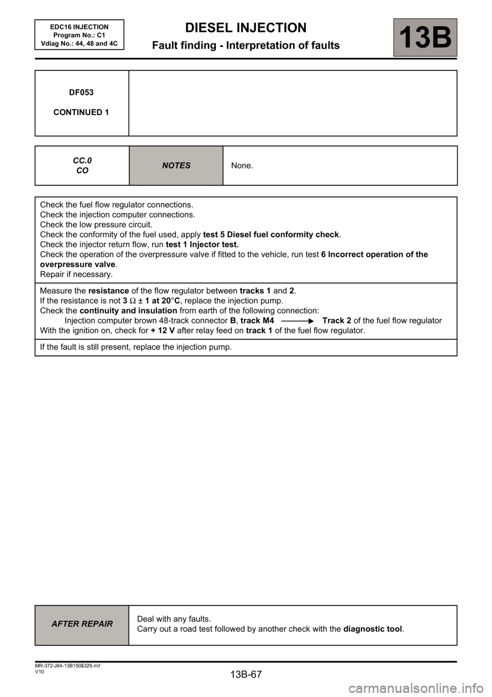
DF053
CONTINUED 1
CC.0
CO
NOTESNone.
Check the fuel flow regulator connections.
Check the injection computer connections.
Check the low pressure circuit.
Check the conformity of the fuel used, apply test 5 Diesel fuel conformity check.
Check the injector return flow, run test 1 Injector test.
Check the operation of the overpressure valve if fitted to the vehicle, run test 6 Incorrect operation of the
overpressure valve.
Repair if necessary.
Measure the resistance of the flow regulator between tracks 1 and 2.
If the resistance is not 3Ω ±1 at 20°C, replace the injection pump.
Check the continuity and insulation from earth of the following connection:
Injection computer brown 48-track connector B, track M4 Track 2 of the fuel flow regulator
With the ignition on, check for + 12 V after relay feed on track 1 of the fuel flow regulator.
If the fault is still present, replace the injection pump.
AFTER REPAIRDeal with any faults.
Carry out a road test followed by another check with the diagnostic tool.
Page 85 of 236
13B-85
DIESEL INJECTION
Fault finding - Interpretation of faults
13B
V10 MR-372-J84-13B150$376.mif
EDC16 INJECTION
Program No.: C1
Vdiag No.: 44, 48 and 4C
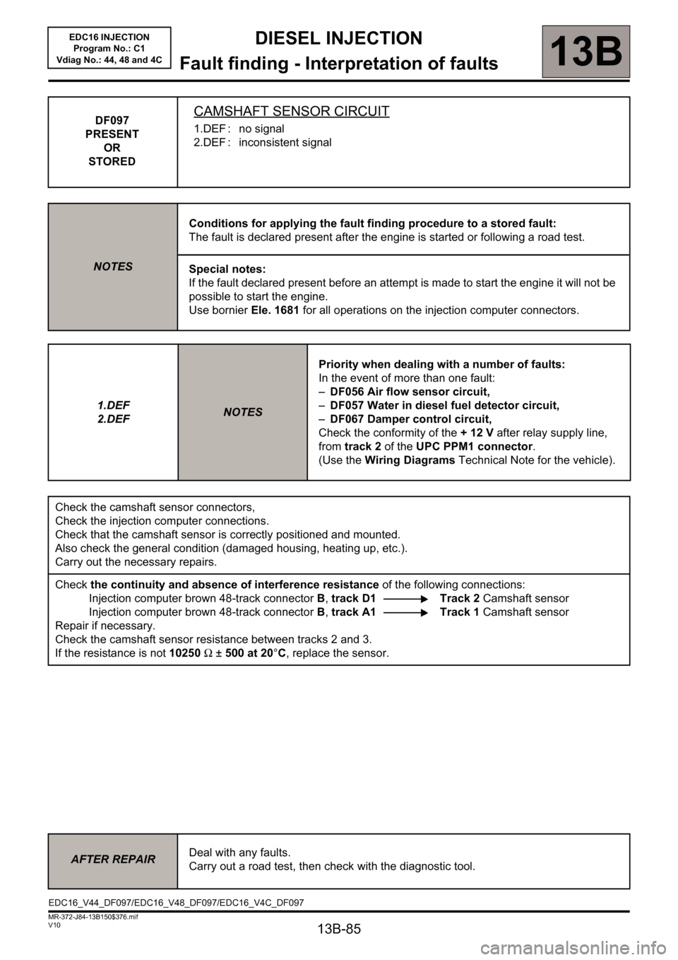
DF097
PRESENT
OR
STOREDCAMSHAFT SENSOR CIRCUIT
1.DEF : no signal
2.DEF : inconsistent signal
NOTESConditions for applying the fault finding procedure to a stored fault:
The fault is declared present after the engine is started or following a road test.
Special notes:
If the fault declared present before an attempt is made to start the engine it will not be
possible to start the engine.
Use bornier Ele. 1681 for all operations on the injection computer connectors.
1.DEF
2.DEF
NOTESPriority when dealing with a number of faults:
In the event of more than one fault:
–DF056 Air flow sensor circuit,
–DF057 Water in diesel fuel detector circuit,
–DF067 Damper control circuit,
Check the conformity of the + 12 V after relay supply line,
from track 2 of the UPC PPM1 connector.
(Use the Wiring Diagrams Technical Note for the vehicle).
Check the camshaft sensor connectors,
Check the injection computer connections.
Check that the camshaft sensor is correctly positioned and mounted.
Also check the general condition (damaged housing, heating up, etc.).
Carry out the necessary repairs.
Check the continuity and absence of interference resistance of the following connections:
Injection computer brown 48-track connector B, track D1 Track 2 Camshaft sensor
Injection computer brown 48-track connector B, track A1 Track 1 Camshaft sensor
Repair if necessary.
Check the camshaft sensor resistance between tracks 2 and 3.
If the resistance is not 10250Ω ±500 at 20°C, replace the sensor.
AFTER REPAIRDeal with any faults.
Carry out a road test, then check with the diagnostic tool.
EDC16_V44_DF097/EDC16_V48_DF097/EDC16_V4C_DF097
Page 100 of 236
13B-100
DIESEL INJECTION
Fault finding - Interpretation of faults
13B
V10 MR-372-J84-13B150$376.mif
EDC16 INJECTION
Program No.: C1
Vdiag No.: 44, 48 and 4C
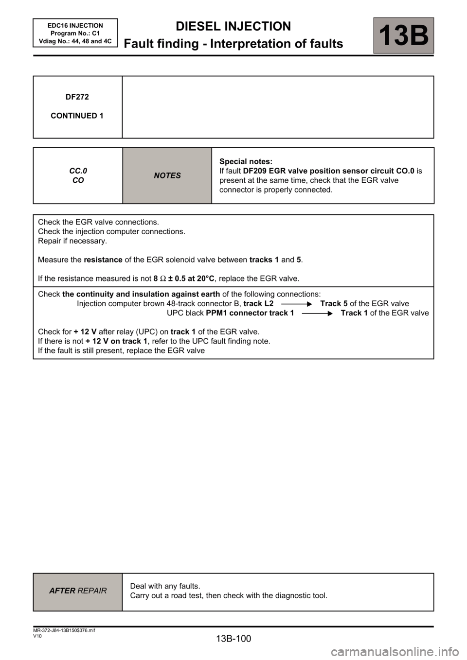
DF272
CONTINUED 1
CC.0
CO
NOTESSpecial notes:
If fault DF209 EGR valve position sensor circuit CO.0 is
present at the same time, check that the EGR valve
connector is properly connected.
Check the EGR valve connections.
Check the injection computer connections.
Repair if necessary.
Measure the resistance of the EGR solenoid valve between tracks 1 and 5.
If the resistance measured is not 8Ω ± 0.5 at 20°C, replace the EGR valve.
Check the continuity and insulation against earth of the following connections:
Injection computer brown 48-track connector B, track L2 Track 5 of the EGR valve
UPC black PPM1 connector track 1 Track 1 of the EGR valve
Check for + 12 V after relay (UPC) on track 1 of the EGR valve.
If there is not + 12 V on track 1, refer to the UPC fault finding note.
If the fault is still present, replace the EGR valve
AFTER REPAIRDeal with any faults.
Carry out a road test, then check with the diagnostic tool.