stop start RENAULT SCENIC 2011 J95 / 3.G Engine And Peripherals EDC16 Injection Workshop Manual
[x] Cancel search | Manufacturer: RENAULT, Model Year: 2011, Model line: SCENIC, Model: RENAULT SCENIC 2011 J95 / 3.GPages: 236, PDF Size: 1.32 MB
Page 21 of 236
13B - 21
DIESEL INJECTION
Fault finding - Replacement of components13B
V10 MR-372-J84-13B150$188.mif
EDC16 INJECTION
Program No.: C1
Vdiag No.: 44, 48 and 4C
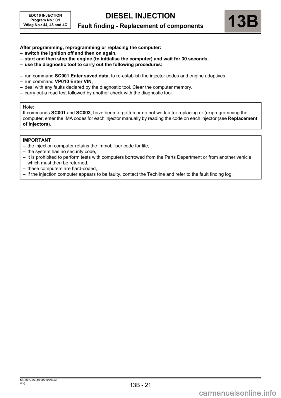
After programming, reprogramming or replacing the computer:
–switch the ignition off and then on again,
–start and then stop the engine (to initialise the computer) and wait for 30 seconds,
–use the diagnostic tool to carry out the following procedures:
– run command SC001 Enter saved data, to re-establish the injector codes and engine adaptives,
– run command VP010 Enter VIN,
– deal with any faults declared by the diagnostic tool. Clear the computer memory.
– carry out a road test followed by another check with the diagnostic tool.
Note:
If commands SC001 and SC003, have been forgotten or do not work after replacing or (re)programming the
computer, enter the IMA codes for each injector manually by reading the code on each injector (see Replacement
of injectors).
IMPORTANT
– the injection computer retains the immobiliser code for life,
– the system has no security code,
– it is prohibited to perform tests with computers borrowed from the Parts Department or from another vehicle
which must then be returned,
– these computers are hard-coded,
– if the injection computer appears to be faulty, contact the Techline and refer to the fault finding log.
Page 32 of 236
13B-32
DIESEL INJECTION
Fault finding - Interpretation of faults13B
V10 MR-372-J84-13B150$282.mif
EDC16 INJECTION
Program No.: C1
Vdiag No.: 44, 48 and 4C
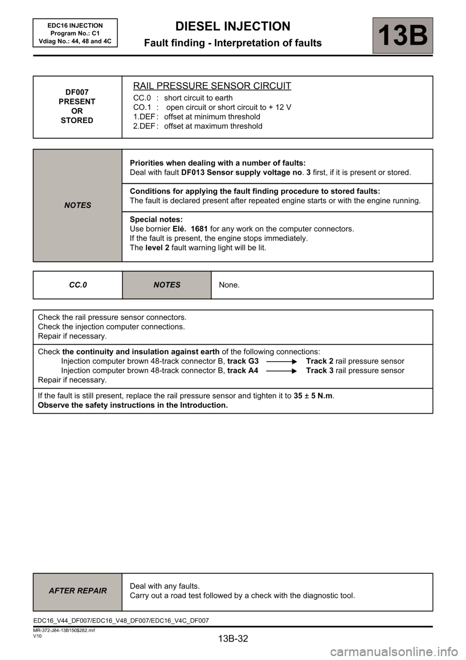
DF007
PRESENT
OR
STOREDRAIL PRESSURE SENSOR CIRCUIT
CC.0 : short circuit to earth
CO.1 : open circuit or short circuit to + 12 V
1.DEF : offset at minimum threshold
2.DEF : offset at maximum threshold
NOTESPriorities when dealing with a number of faults:
Deal with fault DF013 Sensor supply voltage no. 3 first, if it is present or stored.
Conditions for applying the fault finding procedure to stored faults:
The fault is declared present after repeated engine starts or with the engine running.
Special notes:
Use bornier Elé. 1681 for any work on the computer connectors.
If the fault is present, the engine stops immediately.
The level 2 fault warning light will be lit.
CC.0
NOTESNone.
Check the rail pressure sensor connectors.
Check the injection computer connections.
Repair if necessary.
Check the continuity and insulation against earth of the following connections:
Injection computer brown 48-track connector B, track G3 Track 2 rail pressure sensor
Injection computer brown 48-track connector B, track A4 Track 3 rail pressure sensor
Repair if necessary.
If the fault is still present, replace the rail pressure sensor and tighten it to 35 ± 5 N.m.
Observe the safety instructions in the Introduction.
AFTER REPAIRDeal with any faults.
Carry out a road test followed by a check with the diagnostic tool.
EDC16_V44_DF007/EDC16_V48_DF007/EDC16_V4C_DF007
Page 50 of 236
13B-50
DIESEL INJECTION
Fault finding - Interpretation of faults13B
V10 MR-372-J84-13B150$282.mif
EDC16 INJECTION
Program No.: C1
Vdiag No.: 44, 48 and 4C
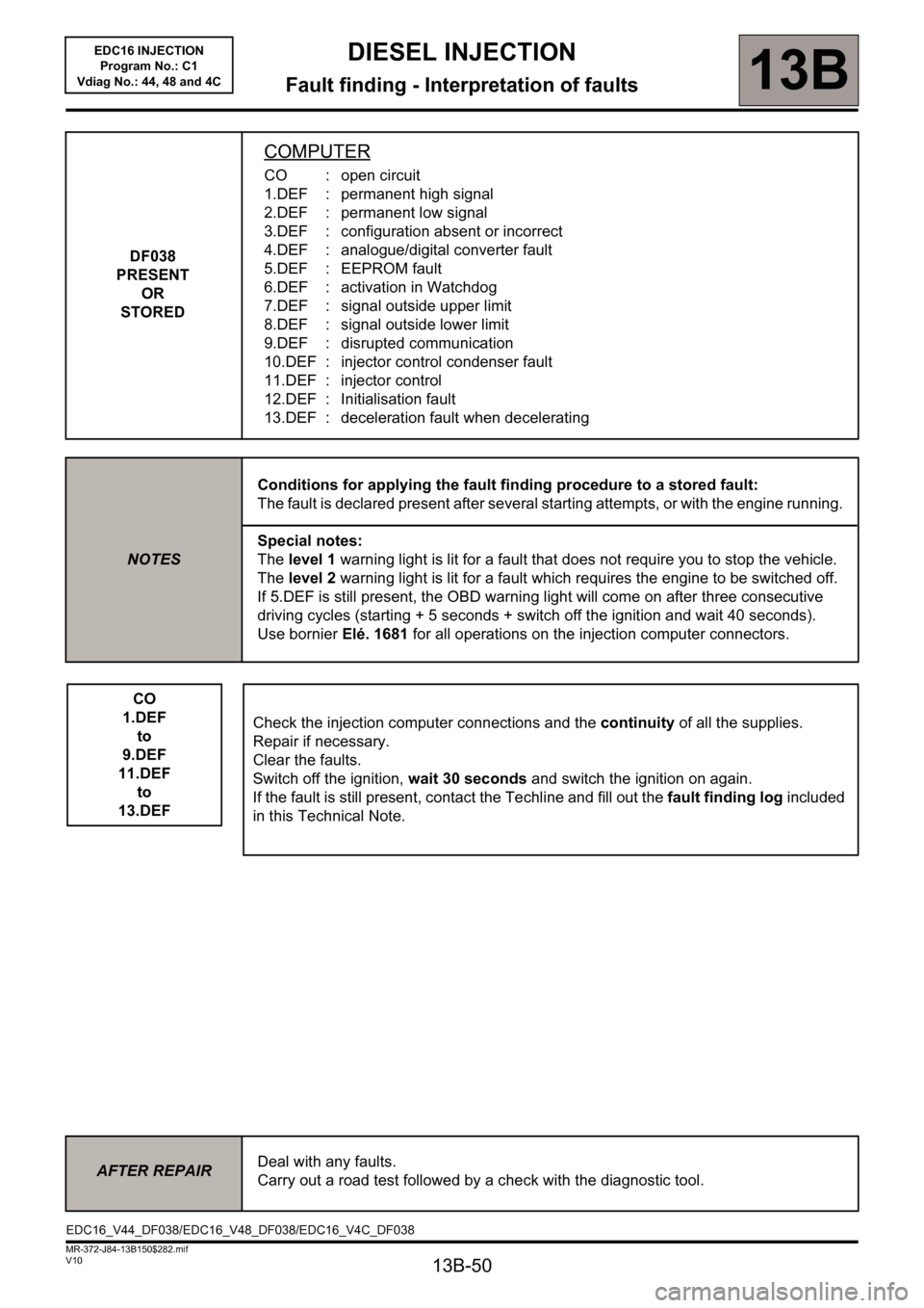
DF038
PRESENT
OR
STORED
COMPUTER
CO : open circuit
1.DEF : permanent high signal
2.DEF : permanent low signal
3.DEF : configuration absent or incorrect
4.DEF : analogue/digital converter fault
5.DEF : EEPROM fault
6.DEF : activation in Watchdog
7.DEF : signal outside upper limit
8.DEF : signal outside lower limit
9.DEF : disrupted communication
10.DEF : injector control condenser fault
11.DEF : injector control
12.DEF : Initialisation fault
13.DEF : deceleration fault when decelerating
NOTESConditions for applying the fault finding procedure to a stored fault:
The fault is declared present after several starting attempts, or with the engine running.
Special notes:
The level 1 warning light is lit for a fault that does not require you to stop the vehicle.
The level 2 warning light is lit for a fault which requires the engine to be switched off.
If 5.DEF is still present, the OBD warning light will come on after three consecutive
driving cycles (starting + 5 seconds + switch off the ignition and wait 40 seconds).
Use bornier Elé. 1681 for all operations on the injection computer connectors.
CO
1.DEF
to
9.DEF
11.DEF
to
13.DEFCheck the injection computer connections and the continuity of all the supplies.
Repair if necessary.
Clear the faults.
Switch off the ignition, wait 30 seconds and switch the ignition on again.
If the fault is still present, contact the Techline and fill out the fault finding log included
in this Technical Note.
AFTER REPAIRDeal with any faults.
Carry out a road test followed by a check with the diagnostic tool.
EDC16_V44_DF038/EDC16_V48_DF038/EDC16_V4C_DF038
Page 126 of 236
13B-126
DIESEL INJECTION
Fault finding - Conformity check13B
V10 MR-372-J84-13B150$423.mif
EDC16 INJECTION
Program No.: C1
Vdiag No: 44, 48 and 4C
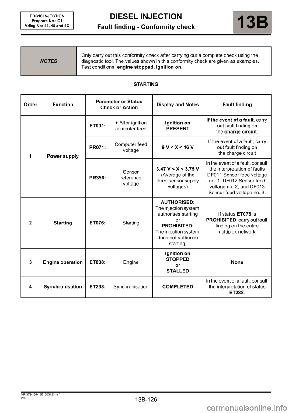
STARTING
NOTESOnly carry out this conformity check after carrying out a complete check using the
diagnostic tool. The values shown in this conformity check are given as examples.
Test conditions: engine stopped, ignition on.
Order FunctionParameter or Status
Check or ActionDisplay and Notes Fault finding
1 Power supplyET001: + After ignition
computer feedIgnition on
PRESENTIf the event of a fault, carry
out fault finding on
thecharge circuit.
PR071:Computer feed
voltage9 V < X < 16 VIf the event of a fault, carry
out fault finding on
the charge circuit
PR358: Sensor
reference
voltage3.47 V < X < 3.75 V
(Average of the
three sensor supply
voltages)In the event of a fault, consult
the interpretation of faults
DF011 Sensor feed voltage
no. 1, DF012 Sensor feed
voltage no. 2, and DF013
Sensor feed voltage no. 3.
2 Starting ET076: StartingAUTHORISED:
The injection system
authorises starting
or
PROHIBITED:
The injection system
does not authorise
starting.If status ET076 is
PROHIBITED, carry out fault
finding on the entire
multiplex network.
3 Engine operation ET038: EngineIgnition on
STOPPED
or
STALLEDNone
4 Synchronisation ET238: SynchronisationCOMPLETEDIn the event of a fault, consult
the interpretation of status
ET238.
Page 127 of 236
13B-127
DIESEL INJECTION
Fault finding - Conformity check13B
V10 MR-372-J84-13B150$423.mif
EDC16 INJECTION
Program No.: C1
Vdiag No: 44, 48 and 4C
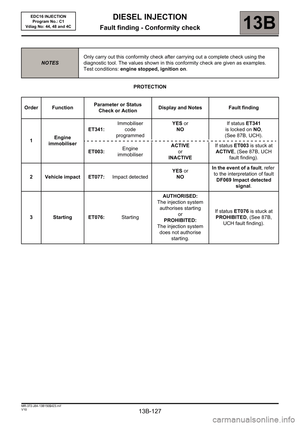
PROTECTION
NOTESOnly carry out this conformity check after carrying out a complete check using the
diagnostic tool. The values shown in this conformity check are given as examples.
Test conditions: engine stopped, ignition on.
Order FunctionParameter or Status
Check or ActionDisplay and Notes Fault finding
1Engine
immobiliserET341: Immobiliser
code
programmedYES or
NOIf status ET341
is locked on NO,
(See 87B, UCH).
ET003: Engine
immobiliserACTIVE
or
INACTIVEIf status ET003 is stuck at
ACTIVE, (See 87B, UCH
fault finding).
2 Vehicle impact ET077: Impact detectedYES or
NOIn the event of a fault, refer
to the interpretation of fault
DF069 Impact detected
signal.
3 Starting ET076: StartingAUTHORISED:
The injection system
authorises starting
or
PROHIBITED:
The injection system
does not authorise
starting.If status ET076 is stuck at
PROHIBITED, (See 87B,
UCH fault finding).
Page 151 of 236
DIESEL INJECTION
Fault finding - Interpretation of statuses13B
13B-151V10 MR-372-J84-13B150$564.mif
EDC16 INJECTION
Program No.: C1
Vdiag No.: 44, 48 and 4C
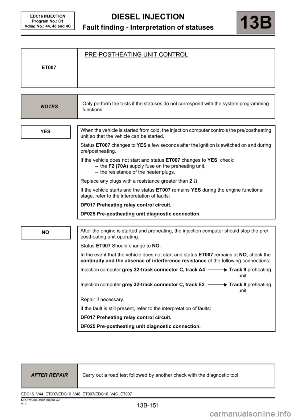
ET007
PRE-POSTHEATING UNIT CONTROL
NOTESOnly perform the tests if the statuses do not correspond with the system programming
functions.
YES
NO
When the vehicle is started from cold, the injection computer controls the pre/postheating
unit so that the vehicle can be started.
Status ET007 changes to YES a few seconds after the ignition is switched on and during
pre/postheating.
If the vehicle does not start and status ET007 changes to YES, check:
–the F2 (70A) supply fuse on the preheating unit,
– the resistance of the heater plugs.
Replace any plugs with a resistance greater than 2 Ω.
If the vehicle starts and the status ET007 remains YES during the engine functional
stage, refer to the interpretation of faults:
DF017 Preheating relay control circuit.
DF025 Pre-postheating unit diagnostic connection.
After the engine is started and preheating, the injection computer should stop the pre/
postheating unit operating.
Status ET007 Should change to NO.
In the event that the vehicle does not start and status ET007 remains at NO, check the
continuity and the absence of interference resistance of the following connections:
Injection computer grey 32-track connector C, track A4 Track 9 preheating
unit
Injection computer grey 32-track connector C, track E2 Track 8 preheating
unit
Repair if necessary.
If the fault is still present, refer to the interpretation of faults:
DF017 Preheating relay control circuit.
DF025 Pre-postheating unit diagnostic connection.
AFTER REPAIRCarry out a road test followed by another check with the diagnostic tool.
EDC16_V44_ET007/EDC16_V48_ET007/EDC16_V4C_ET007
Page 156 of 236

13B-156
DIESEL INJECTION
Fault finding - Interpretation of statuses13B
V10 MR-372-J84-13B150$564.mif
EDC16 INJECTION
Program No.: C1
Vdiag No.: 44, 48 and 4C
ET038
ENGINE
STOPPEDStatus ET038 is stopped if the engine ignition is on but there has been no starter
operation.
STALLEDStatus ET038 is stalled when the engine has stalled. The vehicle is still under + after
ignition feed.
RUNNINGStatus ET038 is running if the engine has started.
STARTINGStatus ET038 is starter if the engine is in starting phase.
AFTER REPAIRCarry out a road test followed by another check with the diagnostic tool.
EDC16_V44_ET038/EDC16_V48_ET038/EDC16_V4C_ET038
Page 166 of 236

DIESEL INJECTION
Fault finding - Interpretation of statuses13B
13B-166V10 MR-372-J84-13B150$564.mif
EDC16 INJECTION
Program No.: C1
Vdiag No.: 44, 48 and 4C
ET238
SYNCHRONISATION
NOTESOnly perform the tests if the statuses do not correspond with the system programming
functions.
WARNING
Synchronisation is carried out during the engine starting phase. This is established between the camshaft
position sensor and the TDC sensor.
Once this synchronisation has been carried out, it enables the computer to identify cylinder no.1 and to
ascertain the precise position of the cylinder's top dead centre.
INACTIVE
COMPLETED
When the engine is stopped but the ignition switched on, cylinder no. 1 is no longer
indicated.
Status ET238 is INACTIVE, no synchronisation between the crankshaft and the
camshaft is performed.
Synchronisation is carried out during the engine starting phase.
Cylinder No. 1 is indicated and synchronisation will be performed once the engine is
started.
Status ET238 is "COMPLETED".
If after several attempts to start the engine status ET238 remains INACTIVE, refer to the
interpretation of the following faults:
–DF005 Engine speed sensor circuit
–DF097 Camshaft sensor circuit
If the engine still does not start, (see Customer complaints, ALP2 Starting faults).
AFTER REPAIRCarry out a road test followed by another check with the diagnostic tool.
EDC16_V44_ET238/EDC16_V48_ET238/EDC16_V4C_ET238
Page 197 of 236
13B - 197
DIESEL INJECTION
Fault finding - Interpretation of commands13B
V10 MR-372-J84-13B150$752.mif
EDC16 INJECTION
Program No.: C1
Vdiag No: 44, 48 and 4C
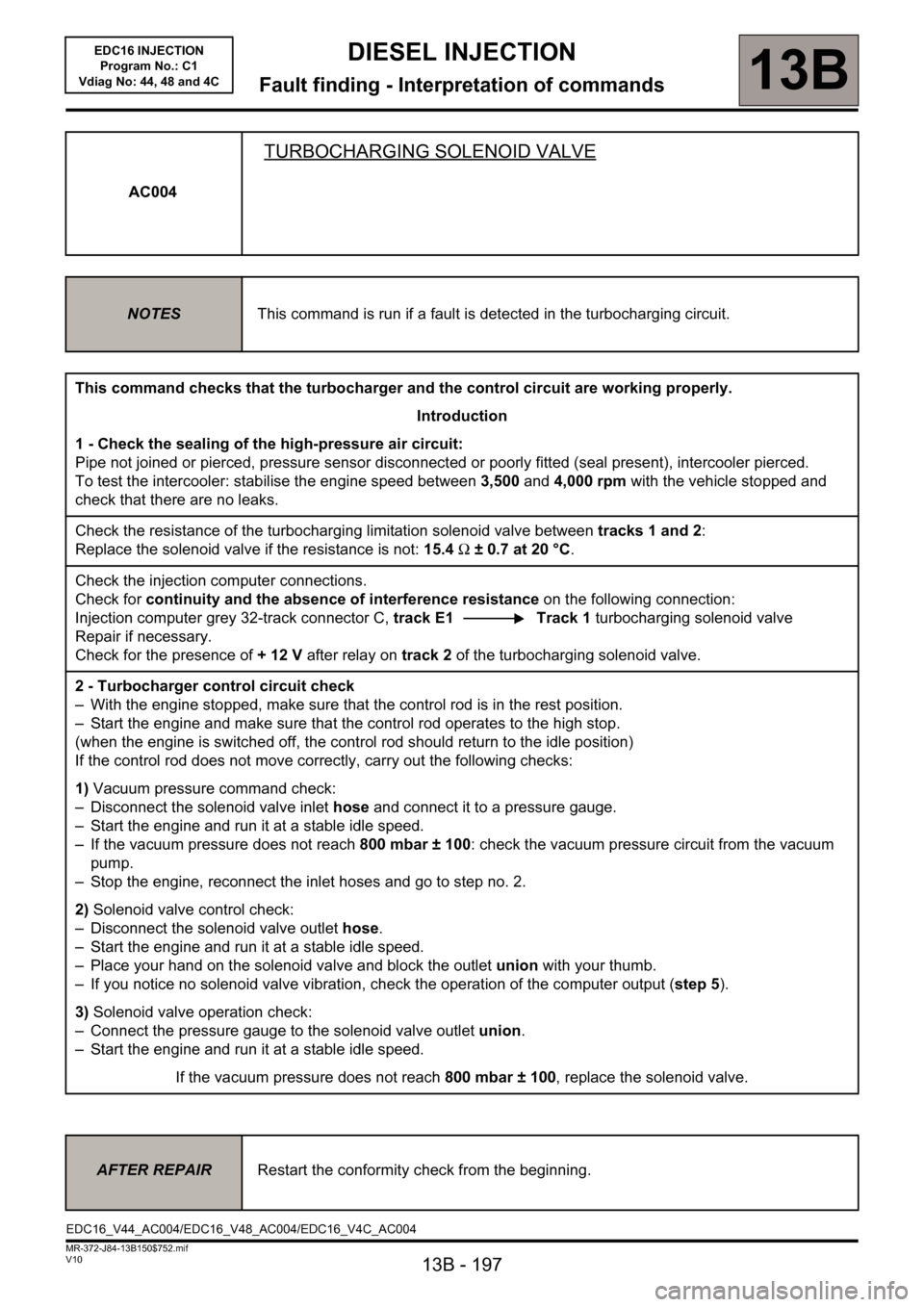
AC004
TURBOCHARGING SOLENOID VALVE
NOTESThis command is run if a fault is detected in the turbocharging circuit.
This command checks that the turbocharger and the control circuit are working properly.
Introduction
1 - Check the sealing of the high-pressure air circuit:
Pipe not joined or pierced, pressure sensor disconnected or poorly fitted (seal present), intercooler pierced.
To test the intercooler: stabilise the engine speed between 3,500 and 4,000 rpm with the vehicle stopped and
check that there are no leaks.
Check the resistance of the turbocharging limitation solenoid valve between tracks 1 and 2:
Replace the solenoid valve if the resistance is not: 15.4 Ω ± 0.7 at 20 °C.
Check the injection computer connections.
Check for continuity and the absence of interference resistance on the following connection:
Injection computer grey 32-track connector C, track E1 Track 1 turbocharging solenoid valve
Repair if necessary.
Check for the presence of +12V after relay on track 2 of the turbocharging solenoid valve.
2 - Turbocharger control circuit check
– With the engine stopped, make sure that the control rod is in the rest position.
– Start the engine and make sure that the control rod operates to the high stop.
(when the engine is switched off, the control rod should return to the idle position)
If the control rod does not move correctly, carry out the following checks:
1) Vacuum pressure command check:
– Disconnect the solenoid valve inlet hose and connect it to a pressure gauge.
– Start the engine and run it at a stable idle speed.
– If the vacuum pressure does not reach 800 mbar ± 100: check the vacuum pressure circuit from the vacuum
pump.
– Stop the engine, reconnect the inlet hoses and go to step no. 2.
2) Solenoid valve control check:
– Disconnect the solenoid valve outlet hose.
– Start the engine and run it at a stable idle speed.
– Place your hand on the solenoid valve and block the outlet union with your thumb.
– If you notice no solenoid valve vibration, check the operation of the computer output (step 5).
3) Solenoid valve operation check:
– Connect the pressure gauge to the solenoid valve outlet union.
– Start the engine and run it at a stable idle speed.
If the vacuum pressure does not reach 800 mbar ± 100, replace the solenoid valve.
AFTER REPAIRRestart the conformity check from the beginning.
EDC16_V44_AC004/EDC16_V48_AC004/EDC16_V4C_AC004
Page 201 of 236
13B - 201
DIESEL INJECTION
Fault finding - Interpretation of commands13B
V10 MR-372-J84-13B150$752.mif
EDC16 INJECTION
Program No.: C1
Vdiag No: 44, 48 and 4C
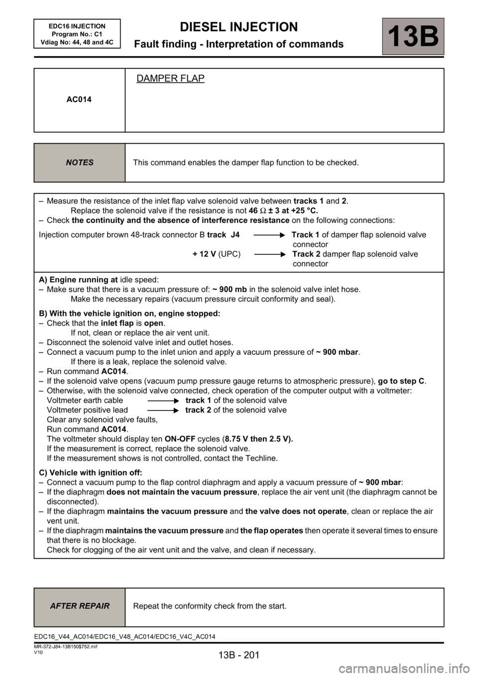
AC014
DAMPER FLAP
NOTESThis command enables the damper flap function to be checked.
– Measure the resistance of the inlet flap valve solenoid valve between tracks 1 and 2.
Replace the solenoid valve if the resistance is not 46 Ω ± 3 at +25 °C.
–Check the continuity and the absence of interference resistance on the following connections:
Injection computer brown 48-track connector B track J4 Track 1 of damper flap solenoid valve
connector
+ 12 V (UPC)Track 2 damper flap solenoid valve
connector
A) Engine running at idle speed:
– Make sure that there is a vacuum pressure of: ~ 900 mb in the solenoid valve inlet hose.
Make the necessary repairs (vacuum pressure circuit conformity and seal).
B) With the vehicle ignition on, engine stopped:
– Check that the inlet flap is open.
If not, clean or replace the air vent unit.
– Disconnect the solenoid valve inlet and outlet hoses.
– Connect a vacuum pump to the inlet union and apply a vacuum pressure of ~ 900 mbar.
If there is a leak, replace the solenoid valve.
– Run command AC014.
– If the solenoid valve opens (vacuum pump pressure gauge returns to atmospheric pressure), go to step C.
– Otherwise, with the solenoid valve connected, check operation of the computer output with a voltmeter:
Voltmeter earth cabletrack 1 of the solenoid valve
Voltmeter positive leadtrack 2 of the solenoid valve
Clear any solenoid valve faults,
Run command AC014.
The voltmeter should display ten ON-OFF cycles (8.75 V then 2.5 V).
If the measurement is correct, replace the solenoid valve.
If the measurement shows is not controlled, contact the Techline.
C) Vehicle with ignition off:
– Connect a vacuum pump to the flap control diaphragm and apply a vacuum pressure of ~ 900 mbar:
– If the diaphragm does not maintain the vacuum pressure, replace the air vent unit (the diaphragm cannot be
disconnected).
– If the diaphragm maintains the vacuum pressure and the valve does not operate, clean or replace the air
vent unit.
– If the diaphragm maintains the vacuum pressure and the flap operates then operate it several times to ensure
that there is no blockage.
Check for clogging of the air vent unit and the valve, and clean if necessary.
AFTER REPAIRRepeat the conformity check from the start.
EDC16_V44_AC014/EDC16_V48_AC014/EDC16_V4C_AC014