cooling RENAULT SCENIC 2011 J95 / 3.G Engine And Peripherals EDC16 Workshop Manual
[x] Cancel search | Manufacturer: RENAULT, Model Year: 2011, Model line: SCENIC, Model: RENAULT SCENIC 2011 J95 / 3.GPages: 365, PDF Size: 2.11 MB
Page 55 of 365
13B-55
MR-372-J84-13B200$252.mif
V13
DIESEL INJECTION
Fault finding – Interpretation of faults
EDC16
Program No.: C1
Vdiag no.: 18, 1C, 20,
50, 58, 5C
13B
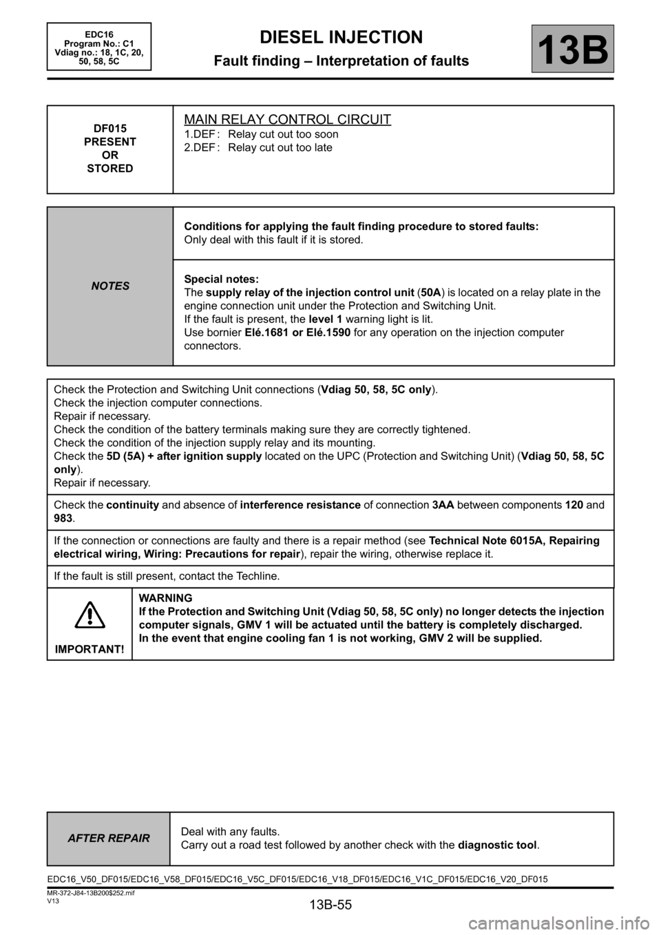
DF015
PRESENT
OR
STOREDMAIN RELAY CONTROL CIRCUIT
1.DEF : Relay cut out too soon
2.DEF : Relay cut out too late
NOTESConditions for applying the fault finding procedure to stored faults:
Only deal with this fault if it is stored.
Special notes:
The supply relay of the injection control unit (50A) is located on a relay plate in the
engine connection unit under the Protection and Switching Unit.
If the fault is present, the level 1 warning light is lit.
Use bornier Elé.1681 or Elé.1590 for any operation on the injection computer
connectors.
Check the Protection and Switching Unit connections (Vdiag 50, 58, 5C only).
Check the injection computer connections.
Repair if necessary.
Check the condition of the battery terminals making sure they are correctly tightened.
Check the condition of the injection supply relay and its mounting.
Check the 5D (5A) + after ignition supply located on the UPC (Protection and Switching Unit) (Vdiag 50, 58, 5C
only).
Repair if necessary.
Check the continuity and absence of interference resistance of connection 3AA between components 120 and
983.
If the connection or connections are faulty and there is a repair method (see Technical Note 6015A, Repairing
electrical wiring, Wiring: Precautions for repair), repair the wiring, otherwise replace it.
If the fault is still present, contact the Techline.
IMPORTANT!WA R N I N G
If the Protection and Switching Unit (Vdiag 50, 58, 5C only) no longer detects the injection
computer signals, GMV 1 will be actuated until the battery is completely discharged.
In the event that engine cooling fan 1 is not working, GMV 2 will be supplied.
AFTER REPAIRDeal with any faults.
Carry out a road test followed by another check with the diagnostic tool.
EDC16_V50_DF015/EDC16_V58_DF015/EDC16_V5C_DF015/EDC16_V18_DF015/EDC16_V1C_DF015/EDC16_V20_DF015
Page 162 of 365
13B-162
MR-372-J84-13B200$468.mif
V13
13B
DIESEL INJECTION
Fault finding – Status summary table
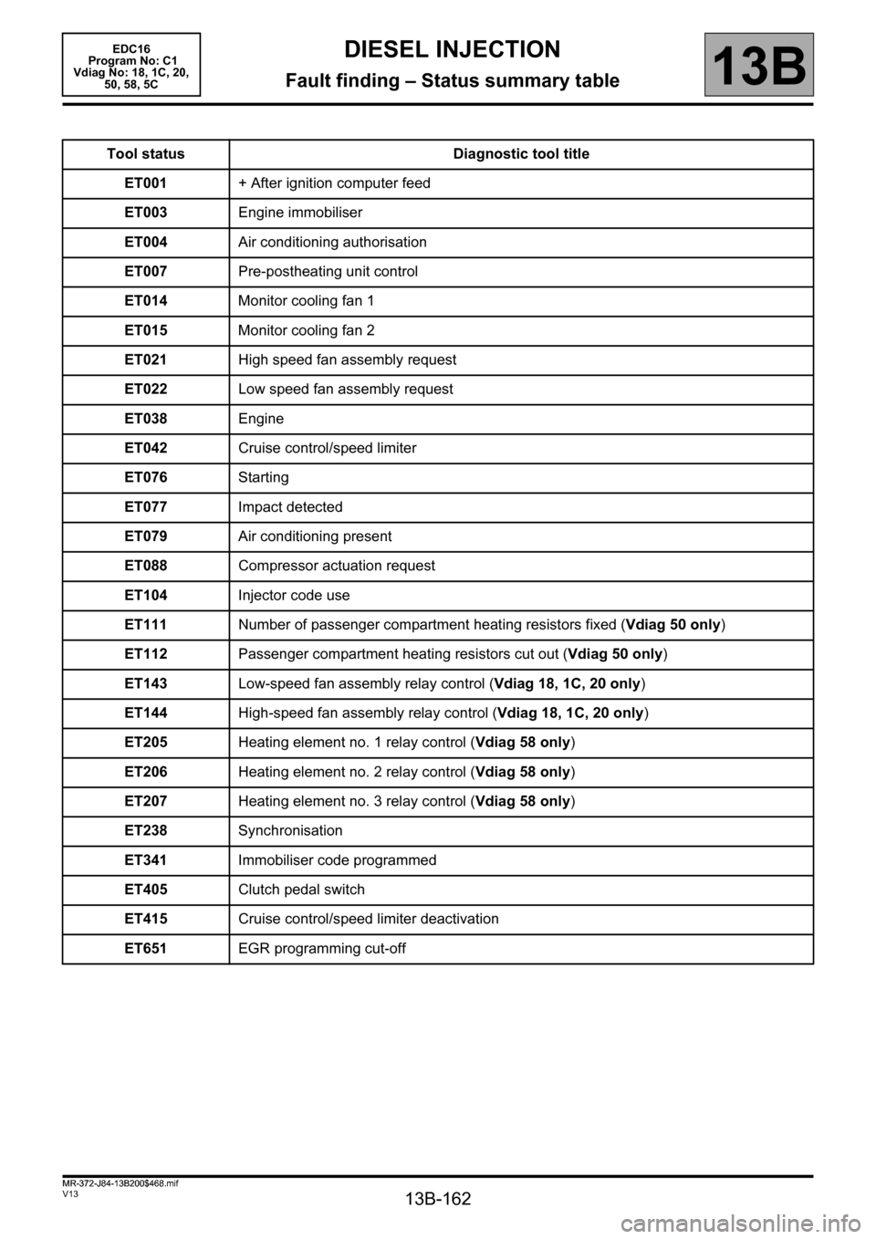
Tool status Diagnostic tool title
ET001+ After ignition computer feed
ET003Engine immobiliser
ET004Air conditioning authorisation
ET007Pre-postheating unit control
ET014Monitor cooling fan 1
ET015Monitor cooling fan 2
ET021High speed fan assembly request
ET022Low speed fan assembly request
ET038Engine
ET042Cruise control/speed limiter
ET076Starting
ET077Impact detected
ET079Air conditioning present
ET088Compressor actuation request
ET104Injector code use
ET111Number of passenger compartment heating resistors fixed (Vdiag 50 only)
ET112Passenger compartment heating resistors cut out (Vdiag 50 only)
ET143Low-speed fan assembly relay control (Vdiag 18, 1C, 20 only)
ET144High-speed fan assembly relay control (Vdiag 18, 1C, 20 only)
ET205Heating element no. 1 relay control (Vdiag 58 only)
ET206Heating element no. 2 relay control (Vdiag 58 only)
ET207Heating element no. 3 relay control (Vdiag 58 only)
ET238Synchronisation
ET341Immobiliser code programmed
ET405Clutch pedal switch
ET415Cruise control/speed limiter deactivation
ET651EGR programming cut-off
EDC16
Program No: C1
Vdiag No: 18, 1C, 20,
50, 58, 5C
MR-372-J84-13B200$468.mif
Page 170 of 365
13B-170
MR-372-J84-13B200$504.mif
V13
EDC16
Program No: C1
Vdiag No: 18, 1C, 20,
50, 58, 5CDIESEL INJECTION
Fault finding – Interpretation of statuses13B
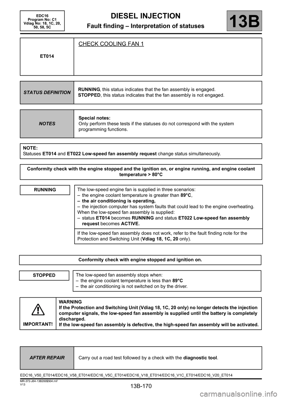
ET014
CHECK COOLING FAN 1
STATUS DEFINITIONRUNNING, this status indicates that the fan assembly is engaged.
STOPPED, this status indicates that the fan assembly is not engaged.
NOTESSpecial notes:
Only perform these tests if the statuses do not correspond with the system
programming functions.
NOTE:
Statuses ET014 and ET022 Low-speed fan assembly request change status simultaneously.
Conformity check with the engine stopped and the ignition on, or engine running, and engine coolant
temperature > 80°C
RUNNING
The low-speed engine fan is supplied in three scenarios:
– the engine coolant temperature is greater than 89°C,
– the air conditioning is operating,
– the injection computer has system faults that could lead to the engine overheating.
When the low-speed fan assembly is supplied:
–status ET014 becomes RUNNING and status ET022 Low-speed fan assembly
request becomes ACTIVE.
If the low-speed fan assembly does not work, refer to the fault finding note for the
Protection and Switching Unit (Vdiag 18, 1C, 20 only).
Conformity check with engine stopped and ignition on.
STOPPEDThe low-speed fan assembly stops when:
– the engine coolant temperature is less than 89°C
– the air conditioning is not switched on by the driver.
IMPORTANT!WARNING
If the Protection and Switching Unit (Vdiag 18, 1C, 20 only) no longer detects the injection
computer signals, the low-speed fan assembly is supplied until the battery is completely
discharged.
If the low-speed fan assembly is defective, the high-speed fan assembly will be activated.
AFTER REPAIRCarry out a road test followed by a check with the diagnostic tool.
EDC16_V50_ET014/EDC16_V58_ET014/EDC16_V5C_ET014/EDC16_V18_ET014/EDC16_V1C_ET014/EDC16_V20_ET014
Page 171 of 365
13B-171
MR-372-J84-13B200$504.mif
V13
EDC16
Program No: C1
Vdiag No: 18, 1C, 20,
50, 58, 5CDIESEL INJECTION
Fault finding – Interpretation of statuses13B
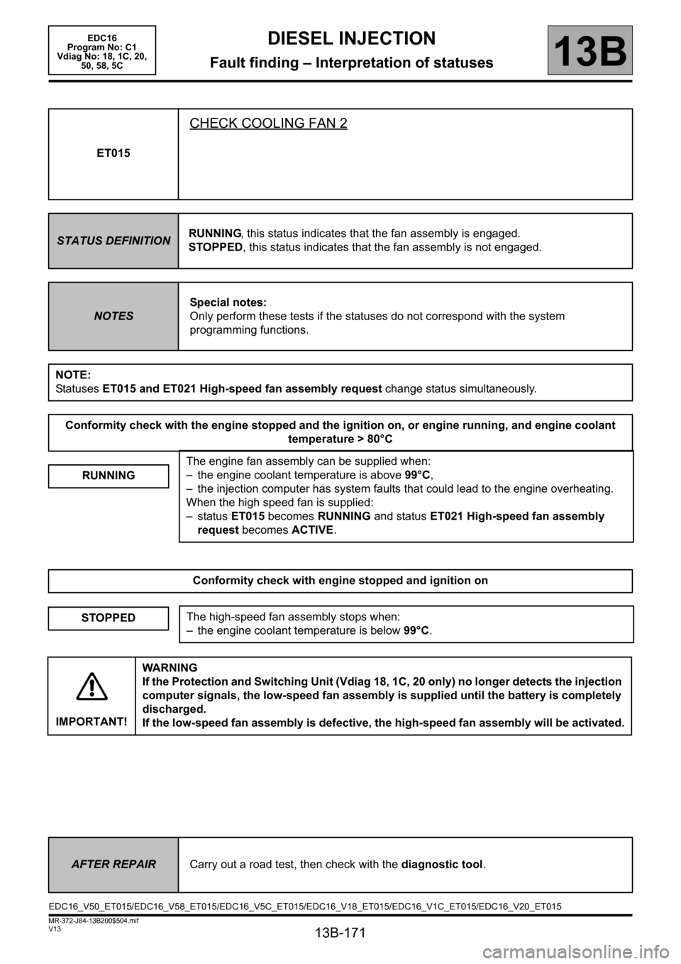
ET015
CHECK COOLING FAN 2
STATUS DEFINITIONRUNNING, this status indicates that the fan assembly is engaged.
STOPPED, this status indicates that the fan assembly is not engaged.
NOTESSpecial notes:
Only perform these tests if the statuses do not correspond with the system
programming functions.
NOTE:
Statuses ET015 and ET021 High-speed fan assembly request change status simultaneously.
Conformity check with the engine stopped and the ignition on, or engine running, and engine coolant
temperature > 80°C
RUNNING
The engine fan assembly can be supplied when:
– the engine coolant temperature is above 99°C,
– the injection computer has system faults that could lead to the engine overheating.
When the high speed fan is supplied:
–status ET015 becomes RUNNING and status ET021 High-speed fan assembly
request becomes ACTIVE.
Conformity check with engine stopped and ignition on
STOPPEDThe high-speed fan assembly stops when:
– the engine coolant temperature is below 99°C.
IMPORTANT!WARNING
If the Protection and Switching Unit (Vdiag 18, 1C, 20 only) no longer detects the injection
computer signals, the low-speed fan assembly is supplied until the battery is completely
discharged.
If the low-speed fan assembly is defective, the high-speed fan assembly will be activated.
AFTER REPAIRCarry out a road test, then check with the diagnostic tool.
EDC16_V50_ET015/EDC16_V58_ET015/EDC16_V5C_ET015/EDC16_V18_ET015/EDC16_V1C_ET015/EDC16_V20_ET015
Page 189 of 365
13B-189
MR-372-J84-13B200$504.mif
V13
13B
DIESEL INJECTION
Fault finding – Interpretation of statuses
ET143
LOW-SPEED FAN ASSEMBLY RELAY CONTROL
STATUS DEFINITIONACTVE: This status indicates that the low-speed fan assembly relay is actuated.
INACTIVE: This status indicates that the low-speed fan assembly relay is not actuated.
NOTESIf the vehicle is fitted with air conditioning, the fan assembly electrical circuit contains
2 relays. The fan assembly speed 1 relay will be actuated when the engine coolant
temperature exceeds 96° and will be dedicated to cooling the engine as long as the
engine coolant temperature does not exceed 99°.
If the engine coolant temperature exceeds 99°, fan assembly speed 2 relay will be
actuated and the engine cooling fan will run more quickly.
ACTIVE
When the coolant reaches 96°C, the diesel computer actuates the low-speed fan
assembly relay and status ET143 becomes ACTIVE.
The relay then supplies the fan assembly and the cooling fan begins to turn.
Run command AC038 Low-speed fan unit relay and check visually that the cooling
fan is turning.
If this is not the case, carry out the following operations:
– check the condition of fuse FM15 (60A) and the motor relay R09,
– disconnect the low-speed and high-speed relays, check their operation and the
condition of the connections.
– repair if necessary,
– check for a + 12 V on connection 3FB of the low speed relay when it is actuated
then check the continuity and the absence of interference resistance on connection
3JN between components 120 and 597.
If the connection or connections are faulty and there is a repair method (see Technical
Note 6015A, Repairing electrical wiring, Wiring: Precautions for repair), repair the
wiring, otherwise replace it.
INACTIVEIf the engine temperature is less than 96°C, the engine cooling fan cannot switch on
and the low-speed fan assembly relay cannot be actuated.
Sta tus ET143 becomes INACTIVE when the control relay and the engine cooling fan
are not supplied.
AFTER REPAIRCarry out a road test, then check with the diagnostic tool.
EDC16_V18_ET143/EDC16_V1C_ET143/EDC16_V20_ET143EDC16
Program No: C1
Vdiag No: 18, 1C, 20
Page 190 of 365
13B-190
MR-372-J84-13B200$504.mif
V13
EDC16
Program No: C1
Vdiag No: 18, 1C, 20DIESEL INJECTION
Fault finding – Interpretation of statuses13B
ET144
HIGH-SPEED FAN ASSEMBLY RELAY CONTROL
STATUS DEFINITIONACTIVE: This status indicates that the high-speed fan assembly relay is actuated.
INACTIVE: This status indicates that the high-speed fan assembly relay is not
actuated.
ACTIVE
When the coolant reaches 99°C, the diesel computer activates the high-speed fan
assembly relay and status ET144 becomes ACTIVE.
The relay then supplies the fan assembly and the cooling fan begins to turn.
Run command AC039 High-speed fan unit relay and visually check that the cooling
fan is turning. If this is not the case, carry out the following operations:
– check the condition of fuse FM15 (60A) and the motor relay R10,
– disconnect the fan unit relays, check their operation and the condition of the
connections,
– repair if necessary,
– check for a + 12 V on connection 49B of components 597 and 262, when the high-
speed relay is actuated.
Check the continuity and the absence of interference resistance on the following
connections:
–Connection codes 3JP and 49B between components 120, 957 and 262.
If the connection or connections are faulty and there is a repair method (see Technical
Note 6015A, Repairing electrical wiring, Wiring: Precautions for repair), repair the
wiring, otherwise replace it.
INACTIVEIf the engine temperature is less than 99°C, the engine cooling fan cannot switch on
and the high-speed fan assembly relay should not be actuated.
Status ET144 becomes INACTIVE when the control relay and the engine cooling fan
are not supplied.
AFTER REPAIRCarry out a road test, then check with the diagnostic tool.
EDC16_V18_ET144/EDC16_V1C_ET144/EDC16_V20_ET144
Page 296 of 365
13B-296
MR-372-J84-13B200$756.mif
V13
DIESEL INJECTION
Fault finding – Interpretation of commands
EDC16
Program No: C1
Vdiag No: 18, 1C, 20,
50, 58, 5C
13B
SC017
CONTINUED 1
DESCRIPTION OF THE PROCESS
particle filter regeneration takes place in 3 stages (values given as a guide only):
–Warm-up phase: the engine speed is fixed or varies between 1000 rpm and 1650 rpm.
This phase lasts at least 3 minutes, until the coolant temperature exceeds 80°C.
–Regeneration phase: the engine speed is fixed or varies between 1000 rpm and 1650 rpm. Engine injection
is retarded. The exhaust fumes rise in temperature and burn the soot retained in the particle filter. The particle
filter downstream temperature starts to rise after the particle filter upstream temperature due to the
volume of the particle filter. Then the combustion of the soot stored in the particle filter causes the particle filter
downstream temperature to increase, possibly reaching more than 700°C depending on the amount of soot in
the filter (with a particle filter upstream temperature of approximately 600°C). This phase lasts between 20
and 25 minutes.
–Cooling phase: the engine speed is fixed or varies between 1000 rpm and 1650 rpm.
Engine injection returns to normal and the exhaust gases cool the particle filter.
This phase lasts 3 minutes. At the end of this period, the engine speed returns to idle speed or remains fixed at
1500 rpm.
The process lasts at least 30 minutes (regeneration time will be increased depending on how long it takes for
the coolant temperature to reach 80°C).
CONFIRMING THE REGENERATION PROCESS:
At the end of regeneration, a message appears to announce whether the regeneration was successful:
●Particle filter regeneration finished:
Consult PR1012 Weight of soot after regeneration. If PR1012 is less than 15 g, the particle filter regeneration
completed correctly. If PR1012 is greater than 15 g, a second particle filter regeneration must be performed using
the command in the diagnostic tool and choose command SC017.
IMPORTANT:
Before performing a second After-Sales regeneration of the particle filter, the engine must be allowed to cool
down for 2 hours with the bonnet open.
Do not systematically change the engine oil before a second After-Sales regeneration.
Consult PR848 Number of regeneration failures. If PR848 is greater than 3, change the engine oil.
●Particle filter too full – replace the particle filter: regeneration has failed. The weight of soot in the particle
filter is so great that it is creating back-pressure. Deal with any faults that appear or replace the particle filter.
Run command SC036 Reinitialise programming and select After particle filter replacement.
Check the weight of soot: PR383 Weight of soot in the particle filter.
If PR383
≥ 1 g. Apply the procedure for test 8 Manual clearing of the soot weight.
Page 309 of 365
13B-309
MR-372-J84-13B200$756.mif
V13
DIESEL INJECTION
Fault finding – Interpretation of commands
EDC16
Program No: C1
Vdiag No: 18, 1C, 20,
50, 58, 5C
13B
AC031
CONTINUED
vdiag 18, 1C, 20:
If the additional heater no. 3 relay does not operate when running command AC031:
Check the additional heater no. 3 relay mounting.
check the engine management computer connections.
Repair if necessary.
if the fault is still present, check as follows that this relay is controlled by the engine management computer:
Disconnect the additional heater no. 3 relay, fit a 50 to 100Ω resistor on the mounting in place of the coil and
connect a voltmeter as follows:
Positive terminal to +12 V battery.
Negative terminal to connection 3JAB of the additional heater no. 3 relay mounting.
Clear the fault and actuate the relay using command AC031.
If the voltmeter shows the battery voltage (two, 2-second ON-OFF cycles), replace the additional heater no. 3
relay.
If the voltmeter does not show the battery voltage (two 2 second ON-OFF cycles), contact the Techline.
If the additional heater no. 3 relay is supplied by command AC031, but there is still a fault with the passenger
compartment heating and demisting, check using a wiring diagram:
– the conformity of the thermoplunger maxi-fuse,
– the presence of + 12 V battery on connection BP9 of the additional heater no. 3 relay mounting,
– the conformity of the additional heater relay 3;
– the continuity between connection 3JAC of the additional heater no. 3 relay mounting and the supply terminal
for thermoplunger no. 3.
– the conformity of the thermoplunger resistance: 0.4 Ω < X < 0.5 Ω at 20 °C,
– the presence of earth at the water chamber (thermoplunger mounting).
Also check the level of the cooling circuit and that there are no leaks.
Carry out the necessary repairs.
Page 310 of 365
13B-310
MR-372-J84-13B200$756.mif
V13
DIESEL INJECTION
Fault finding – Interpretation of commands
EDC16
Program No: C1
Vdiag No: 18, 1C, 20,
50, 58, 5C
13B
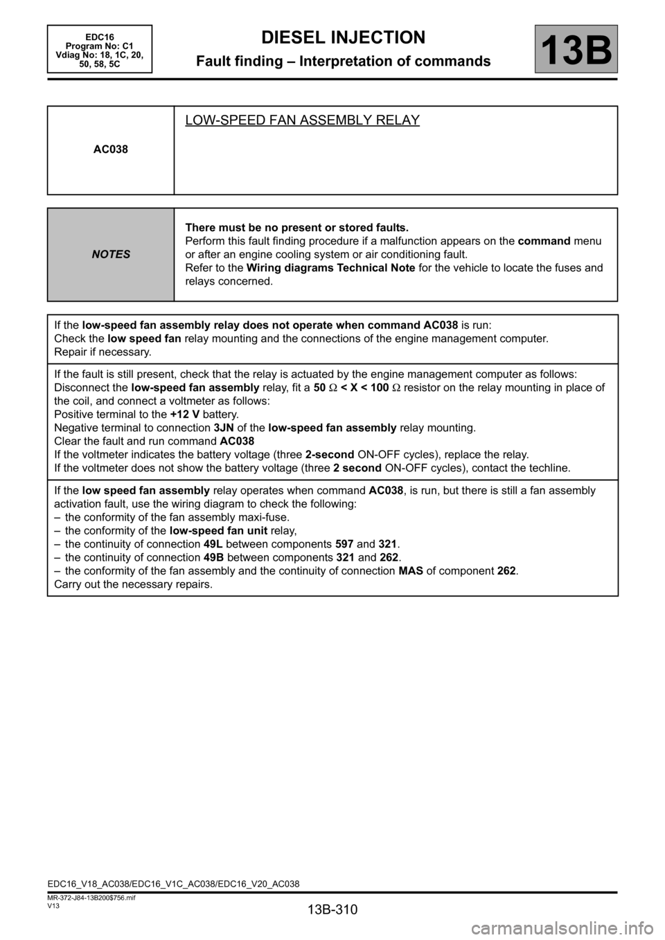
AC038
LOW-SPEED FAN ASSEMBLY RELAY
NOTESThere must be no present or stored faults.
Perform this fault finding procedure if a malfunction appears on the command menu
or after an engine cooling system or air conditioning fault.
Refer to the Wiring diagrams Technical Note for the vehicle to locate the fuses and
relays concerned.
If the low-speed fan assembly relay does not operate when command AC038 is run:
Check the low speed fan relay mounting and the connections of the engine management computer.
Repair if necessary.
If the fault is still present, check that the relay is actuated by the engine management computer as follows:
Disconnect the low-speed fan assembly relay, fit a 50 Ω < X < 100 Ω resistor on the relay mounting in place of
the coil, and connect a voltmeter as follows:
Positive terminal to the +12 V battery.
Negative terminal to connection 3JN of the low-speed fan assembly relay mounting.
Clear the fault and run command AC038
If the voltmeter indicates the battery voltage (three 2-second ON-OFF cycles), replace the relay.
If the voltmeter does not show the battery voltage (three 2 second ON-OFF cycles), contact the techline.
If the low speed fan assembly relay operates when command AC038, is run, but there is still a fan assembly
activation fault, use the wiring diagram to check the following:
– the conformity of the fan assembly maxi-fuse.
– the conformity of the low-speed fan unit relay,
– the continuity of connection 49L between components 597 and 321.
– the continuity of connection 49B between components 321 and 262.
– the conformity of the fan assembly and the continuity of connection MAS of component 262.
Carry out the necessary repairs.
EDC16_V18_AC038/EDC16_V1C_AC038/EDC16_V20_AC038
Page 311 of 365
13B-311
MR-372-J84-13B200$756.mif
V13
DIESEL INJECTION
Fault finding – Interpretation of commands
EDC16
Program No: C1
Vdiag No: 18, 1C, 20,
50, 58, 5C
13B
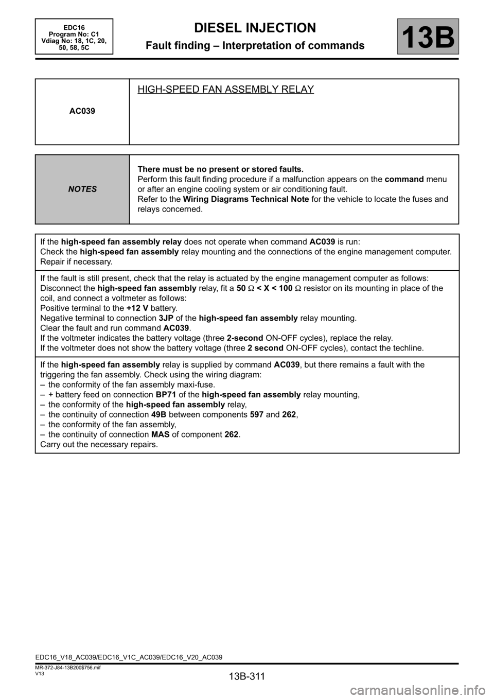
AC039
HIGH-SPEED FAN ASSEMBLY RELAY
NOTESThere must be no present or stored faults.
Perform this fault finding procedure if a malfunction appears on the command menu
or after an engine cooling system or air conditioning fault.
Refer to the Wiring Diagrams Technical Note for the vehicle to locate the fuses and
relays concerned.
If the high-speed fan assembly relay does not operate when command AC039 is run:
Check the high-speed fan assembly relay mounting and the connections of the engine management computer.
Repair if necessary.
If the fault is still present, check that the relay is actuated by the engine management computer as follows:
Disconnect the high-speed fan assembly relay, fit a 50 Ω < X < 100 Ω resistor on its mounting in place of the
coil, and connect a voltmeter as follows:
Positive terminal to the +12 V battery.
Negative terminal to connection 3JP of the high-speed fan assembly relay mounting.
Clear the fault and run command AC039.
If the voltmeter indicates the battery voltage (three 2-second ON-OFF cycles), replace the relay.
If the voltmeter does not show the battery voltage (three 2 second ON-OFF cycles), contact the techline.
If the high-speed fan assembly relay is supplied by command AC039, but there remains a fault with the
triggering the fan assembly. Check using the wiring diagram:
– the conformity of the fan assembly maxi-fuse.
– + battery feed on connection BP71 of the high-speed fan assembly relay mounting,
– the conformity of the high-speed fan assembly relay,
– the continuity of connection 49B between components 597 and 262,
– the conformity of the fan assembly,
– the continuity of connection MAS of component 262.
Carry out the necessary repairs.
EDC16_V18_AC039/EDC16_V1C_AC039/EDC16_V20_AC039