cooling RENAULT SCENIC 2011 J95 / 3.G Engine And Peripherals EDC16 User Guide
[x] Cancel search | Manufacturer: RENAULT, Model Year: 2011, Model line: SCENIC, Model: RENAULT SCENIC 2011 J95 / 3.GPages: 365, PDF Size: 2.11 MB
Page 313 of 365

13B-313
MR-372-J84-13B200$756.mif
V13
DIESEL INJECTION
Fault finding – Interpretation of commands
EDC16
Program No: C1
Vdiag No: 18, 1C, 20,
50, 58, 5C
13B
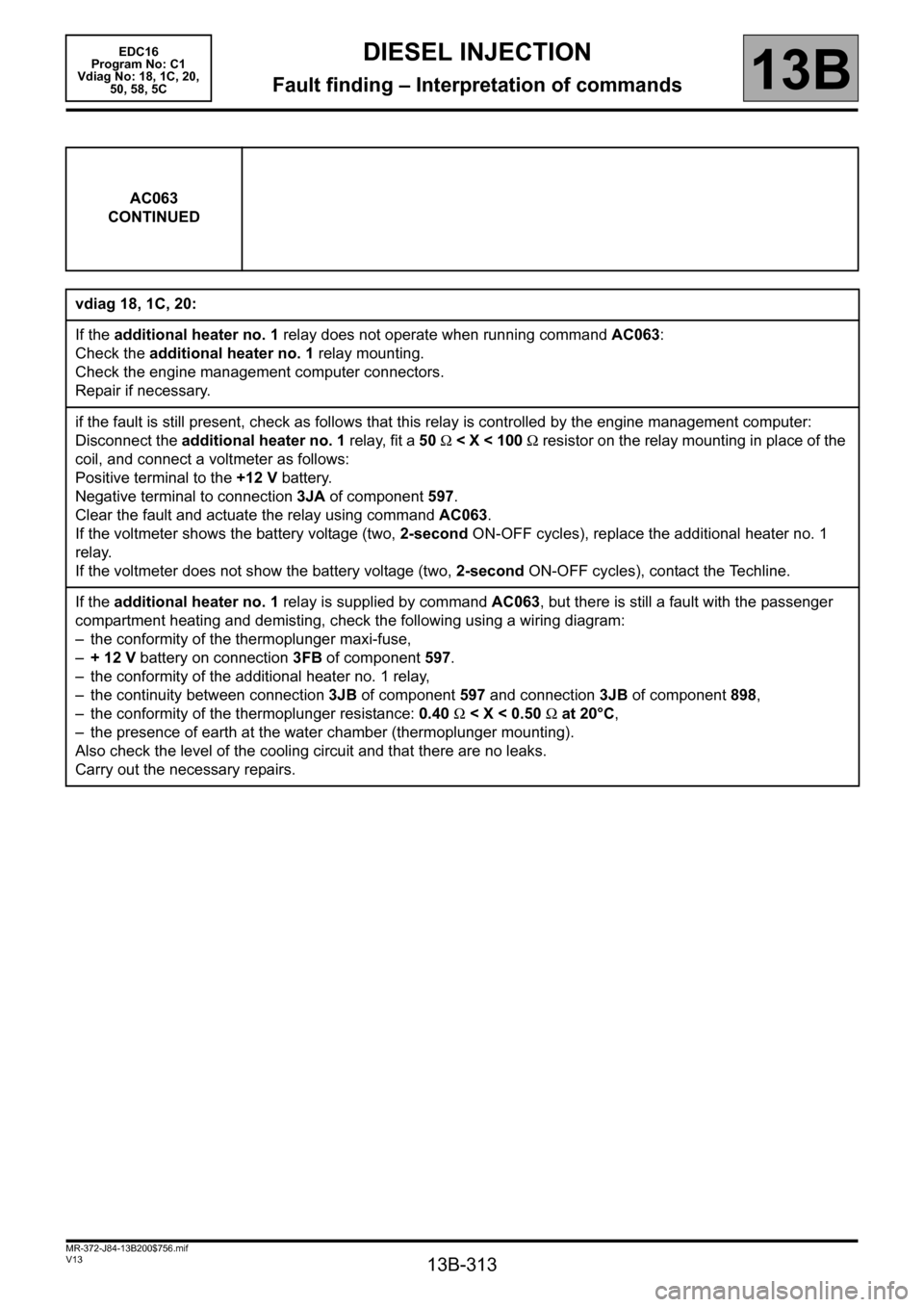
AC063
CONTINUED
vdiag 18, 1C, 20:
If the additional heater no. 1 relay does not operate when running command AC063:
Check the additional heater no. 1 relay mounting.
Check the engine management computer connectors.
Repair if necessary.
if the fault is still present, check as follows that this relay is controlled by the engine management computer:
Disconnect the additional heater no. 1 relay, fit a 50 Ω < X < 100 Ω resistor on the relay mounting in place of the
coil, and connect a voltmeter as follows:
Positive terminal to the +12 V battery.
Negative terminal to connection 3JA of component 597.
Clear the fault and actuate the relay using command AC063.
If the voltmeter shows the battery voltage (two, 2-second ON-OFF cycles), replace the additional heater no. 1
relay.
If the voltmeter does not show the battery voltage (two, 2-second ON-OFF cycles), contact the Techline.
If the additional heater no. 1 relay is supplied by command AC063, but there is still a fault with the passenger
compartment heating and demisting, check the following using a wiring diagram:
– the conformity of the thermoplunger maxi-fuse,
–+12V battery on connection 3FB of component 597.
– the conformity of the additional heater no. 1 relay,
– the continuity between connection 3JB of component 597 and connection 3JB of component 898,
– the conformity of the thermoplunger resistance: 0.40 Ω < X < 0.50 Ω at 20°C,
– the presence of earth at the water chamber (thermoplunger mounting).
Also check the level of the cooling circuit and that there are no leaks.
Carry out the necessary repairs.
Page 315 of 365

13B-315
MR-372-J84-13B200$756.mif
V13
DIESEL INJECTION
Fault finding – Interpretation of commands
EDC16
Program No: C1
Vdiag No: 18, 1C, 20,
50, 58, 5C
13B
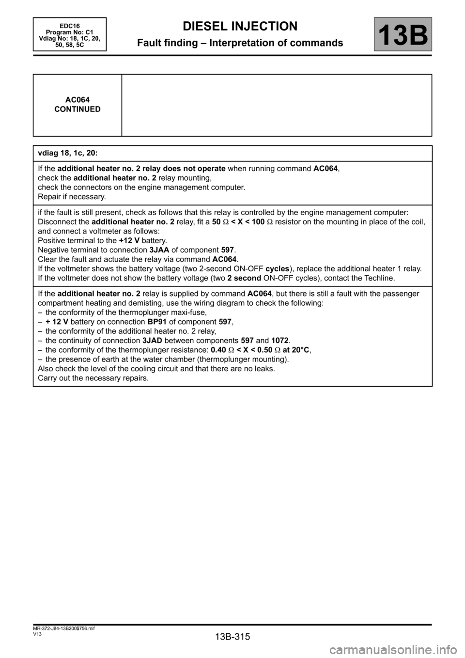
AC064
CONTINUED
vdiag 18, 1c, 20:
If the additional heater no. 2 relay does not operate when running command AC064,
check the additional heater no. 2 relay mounting,
check the connectors on the engine management computer.
Repair if necessary.
if the fault is still present, check as follows that this relay is controlled by the engine management computer:
Disconnect the additional heater no. 2 relay, fit a 50 Ω < X < 100 Ω resistor on the mounting in place of the coil,
and connect a voltmeter as follows:
Positive terminal to the +12 V battery.
Negative terminal to connection 3JAA of component 597.
Clear the fault and actuate the relay via command AC064.
If the voltmeter shows the battery voltage (two 2-second ON-OFF cycles), replace the additional heater 1 relay.
If the voltmeter does not show the battery voltage (two 2 second ON-OFF cycles), contact the Techline.
If the additional heater no. 2 relay is supplied by command AC064, but there is still a fault with the passenger
compartment heating and demisting, use the wiring diagram to check the following:
– the conformity of the thermoplunger maxi-fuse,
–+12V battery on connection BP91 of component 597,
– the conformity of the additional heater no. 2 relay,
– the continuity of connection 3JAD between components 597 and 1072.
– the conformity of the thermoplunger resistance: 0.40 Ω < X < 0.50 Ω at 20°C,
– the presence of earth at the water chamber (thermoplunger mounting).
Also check the level of the cooling circuit and that there are no leaks.
Carry out the necessary repairs.