torque RENAULT SCENIC 2011 J95 / 3.G Engine And Peripherals EDC16 Workshop Manual
[x] Cancel search | Manufacturer: RENAULT, Model Year: 2011, Model line: SCENIC, Model: RENAULT SCENIC 2011 J95 / 3.GPages: 365, PDF Size: 2.11 MB
Page 11 of 365
13B-11
MR-372-J84-13B200$108.mif
V13
13B
DIESEL INJECTION
Fault finding – System operation
System outline
The high pressure injection system is designed to deliver a precise quantity of diesel fuel to the engine at a set
moment.
It is fitted with a 112-track BOSCH EDC16 C3 type computer.
The system comprises:
– a priming bulb on the low pressure circuit,
– a diesel filter,
– a high pressure pump with a built-in low pressure pump (transfer pump),
– a high pressure regulator mounted on the pump,
– an injector rail,
– a diesel fuel pressure sensor built into the rail,
– four solenoid injectors,
– a coolant temperature sensor,
– a cylinder reference sensor,
– an engine speed sensor,
– a turbocharger pressure sensor,
– an accelerator pedal potentiometer,
– an EGR solenoid valve,
– an atmospheric pressure sensor integrated into the injection computer,
– an air flowmeter with an air temperature sensor,
– a turbocharging pressure limitation solenoid valve,
– a motorised damper valve,
– a particle filter,
– a particle filter differential pressure sensor,
– a particle filter upstream temperature sensor,
– a particle filter downstream temperature sensor,
– a temperature sensor upstream of the turbine,
– four thermoplungers
The common rail direct high pressure injection system works sequentially (based on the petrol engine multipoint
injection).
This injection system reduces operating noise, reduces the volume of pollutant gases and particles and produces
high engine torque at low engine speeds thanks to a pre-injection procedure.
The high pressure pump generates the high pressure and transmits it to the injector rail. The actuator located on the
pump controls the quantity of diesel fuel supplied, according to the requirement determined by the computer. The rail
supplies each injector through a steel pipe.
MR-372-J84-13B200$108.mif
EDC16
Program No: C1
Vdiag No: 18, 1C, 20,
50, 58, 5C
Page 40 of 365
13B-40
MR-372-J84-13B200$252.mif
V13
DIESEL INJECTION
Fault finding – Interpretation of faults
EDC16
Program No.: C1
Vdiag no.: 18, 1C, 20,
50, 58, 5C
13B
DF008
PRESENT
OR
STOREDPEDAL POTENTIOMETER CIRCUIT GANG 1
CO.0: Open circuit or short circuit to earth
CC.1 : Short circuit to + 12 V
1.DEF: Inconsistent signal
2.DEF: Accelerator pedal sensor locked
NOTESConditions for applying the fault finding procedure to stored faults:
The fault is declared present after a series of full-load/no-load actions on the
accelerator pedal.
Special notes:
Turbocharging, passenger compartment heating resistor activation and the cruise
control/speed limiter are not authorised.
If CO.0, CC.1 or 1.DEF is present the level 1 warning light is lit.
The engine speed is fixed at 1400 rpm if there is a fault on gangs 1 and 2 of the pedal
potentiometer and the engine torque is limited.
Use bornier Elé. 1681 or Elé. 1590 for all operations on the computer connectors.
Priorities when dealing with a number of faults:
Deal with fault first if it is DF011 Sensor feed voltage no. 1 first if it is present or
stored.
WARNING
This fault may appear if the wiring harness has been damaged.
Follow the procedure described in the Wiring Check in the Introduction.
This check enables the condition and the conformity of the engine wiring harness to be checked.
CO.0
NOTESPriorities when dealing with a number of faults:
If fault DF009 Pedal potentiometer circuit gang 2 is
present at the same time, check that the pedal sensor
connector is connected correctly.
Check the pedal potentiometer connections.
Check the injection computer connections.
Repair if necessary.
Check the continuity and insulation to earth of the following connections:
– connection code 3KW,
– connection code 3LR,
between components 120 and 921.
If the connection or connections are faulty and there is a repair method (see Technical Note 6015A, Repairing
electrical wiring, Wiring: Precautions for repair), repair the wiring, otherwise replace it.
Measure the resistance of the pedal potentiometer on gang 1 between connections 3LR and 3LT.
Replace the pedal potentiometer if the resistance is not approximately 0.8 kΩ < X < 2.6 kΩ.
AFTER REPAIRDeal with any faults.
Carry out a road test followed by another check with the diagnostic tool.
EDC16_V50_DF008/EDC16_V58_DF008/EDC16_V5C_DF008/EDC16_V18_DF008/EDC16_V1C_DF008/EDC16_V20_DF008
Page 43 of 365
13B-43
MR-372-J84-13B200$252.mif
V13
DIESEL INJECTION
Fault finding – Interpretation of faults
EDC16
Program No.: C1
Vdiag no.: 18, 1C, 20,
50, 58, 5C
13B
DF009
PRESENT
OR
STOREDPEDAL POTENTIOMETER CIRCUIT GANG 2
CO.0: Open circuit or short circuit to earth
CC.1 : Short circuit to + 12 V
1.DEF: Inconsistent signal
NOTESConditions for applying the fault finding procedure to stored faults:
The fault is declared present after a series of full-load/no-load actions on the
accelerator pedal.
Special notes:
Turbocharging, passenger compartment heating resistor activation and the cruise
control/speed limiter are not authorised.
If the fault is present, the level 1 warning light is lit.
The engine speed is fixed at 1400 rpm if there is a fault on gangs 1 and 2 of the pedal
potentiometer and the engine torque is limited.
Use bornier Ele. 1681 or Ele. 1590 for all operations on the computer connectors.
Priorities when dealing with a number of faults:
Deal with fault DF012 Sensor supply voltage no. 2 first if it is present or stored.
WARNING
This fault may appear if the wiring harness has been damaged.
Follow the procedure described in the Wiring Check in the Introduction.
This check enables the condition and the conformity of the engine wiring harness to be checked.
AFTER REPAIRDeal with any faults.
Carry out a road test followed by another check with the diagnostic tool.
EDC16_V50_DF009/EDC16_V58_DF009/EDC16_V5C_DF009/EDC16_V18_DF009/EDC16_V1C_DF009/EDC16_V20_DF009
Page 187 of 365
13B-187
MR-372-J84-13B200$504.mif
V13
EDC16
Program No: C1
Vdiag No: 18, 1C, 20,
50, 58, 5CDIESEL INJECTION
Fault finding – Interpretation of statuses13B
ET111
SET NUMBER OF PASSENGER COMPARTMENT HEATING
RESISTORS
STATUS DEFINITIONYES: This status indicates that the number of activated passenger compartment
heating resistors is set by the injection computer.
NO: This status indicates that the number of passenger compartment heating resistors
can be freely controlled by the UCH.
NOTESSpecial notes:
Only perform these tests if the statuses do not correspond with the system
programming functions.
Conformity check with the engine stopped and the ignition on, or engine running, and engine coolant
temperature > 80°C
YES
Depending on the requirements of the injection system (power requirement, torque
reduction, etc.), the injection computer fixes the number of controlled passenger
compartment heating resistors (no more, no less).
Status ET111 becomes YES when the number of activated passenger compartment
heating resistors is set by the injection computer.
NODepending on the requirements of the injection system (power requirement, torque
reduction, etc.), the injection computer fixes the number of controlled passenger
compartment heating resistors (no more, no less).
Status ET111 becomes NO when the number of activated passenger compartment
heating resistors can be freely controlled by the UCH.
AFTER REPAIRCarry out a road test followed by a check with the diagnostic tool.
EDC16_V50_ET111/EDC16_V58_ET111/EDC16_V5C_ET111/EDC16_V18_ET111/EDC16_V1C_ET111/EDC16_V20_ET111
Page 188 of 365
13B-188
MR-372-J84-13B200$504.mif
V13
EDC16
Program No: C1
Vdiag No: 18, 1C, 20,
50, 58, 5CDIESEL INJECTION
Fault finding – Interpretation of statuses13B
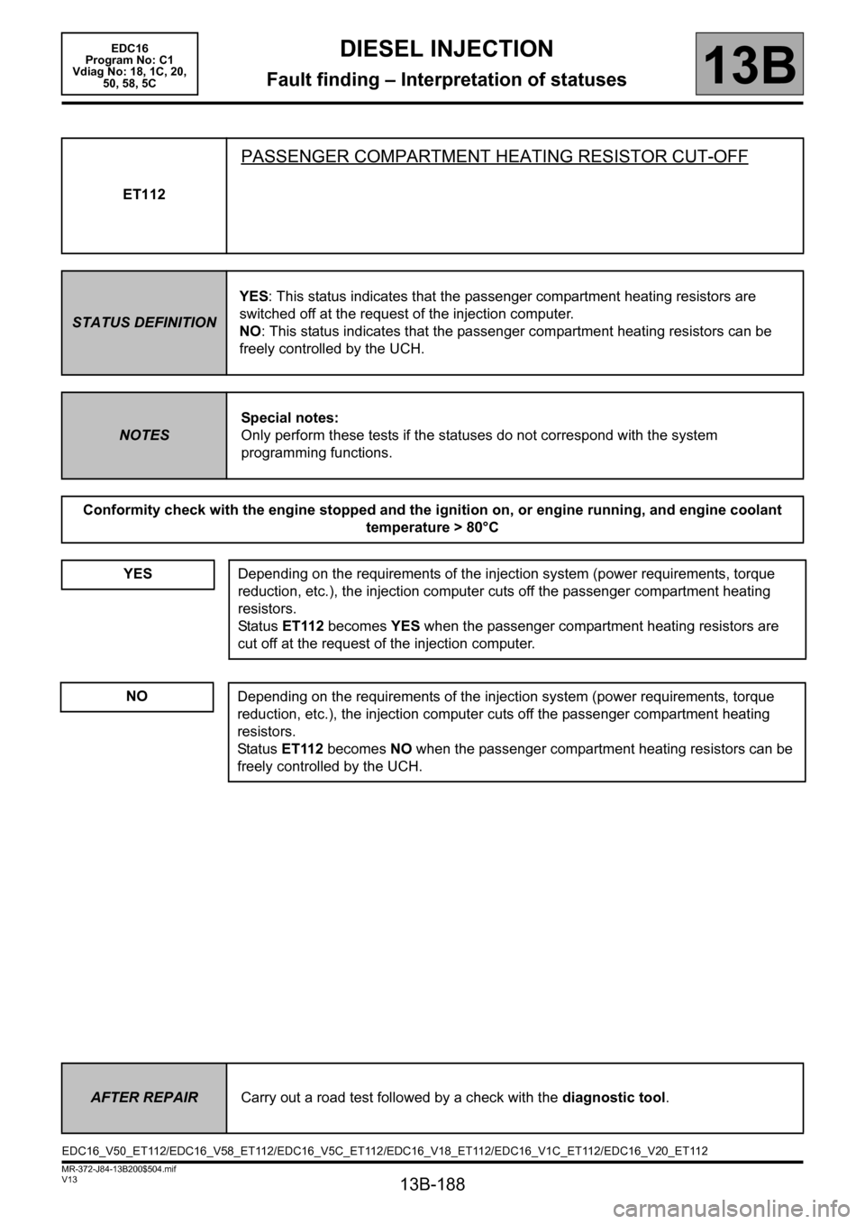
ET112
PASSENGER COMPARTMENT HEATING RESISTOR CUT-OFF
STATUS DEFINITIONYES: This status indicates that the passenger compartment heating resistors are
switched off at the request of the injection computer.
NO: This status indicates that the passenger compartment heating resistors can be
freely controlled by the UCH.
NOTESSpecial notes:
Only perform these tests if the statuses do not correspond with the system
programming functions.
Conformity check with the engine stopped and the ignition on, or engine running, and engine coolant
temperature > 80°C
YES
Depending on the requirements of the injection system (power requirements, torque
reduction, etc.), the injection computer cuts off the passenger compartment heating
resistors.
Status ET112 becomes YES when the passenger compartment heating resistors are
cut off at the request of the injection computer.
NODepending on the requirements of the injection system (power requirements, torque
reduction, etc.), the injection computer cuts off the passenger compartment heating
resistors.
Status ET112 becomes NO when the passenger compartment heating resistors can be
freely controlled by the UCH.
AFTER REPAIRCarry out a road test followed by a check with the diagnostic tool.
EDC16_V50_ET112/EDC16_V58_ET112/EDC16_V5C_ET112/EDC16_V18_ET112/EDC16_V1C_ET112/EDC16_V20_ET112
Page 210 of 365
13B-210
MR-372-J84-13B200$576.mif
V13
13B
DIESEL INJECTION
Fault finding – Parameter summary table
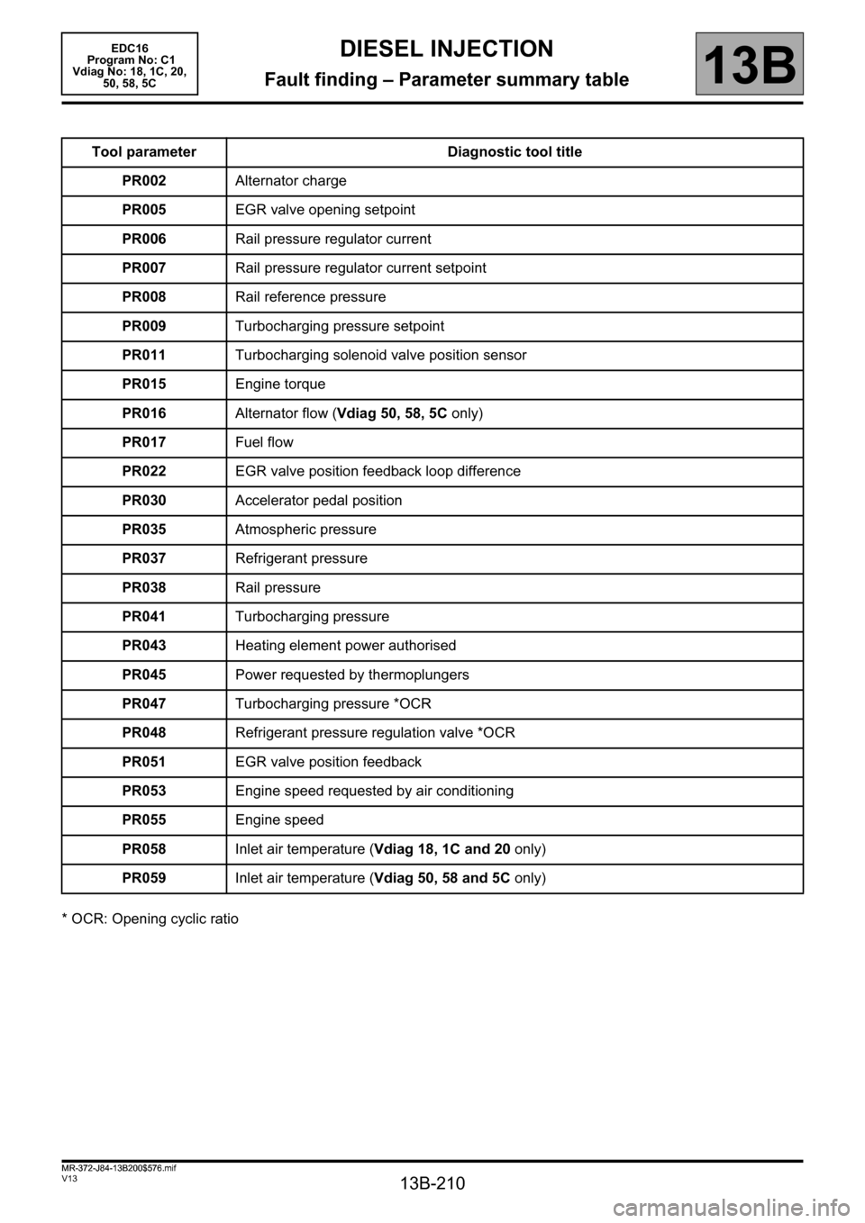
* OCR: Opening cyclic ratioTool parameter Diagnostic tool title
PR002Alternator charge
PR005EGR valve opening setpoint
PR006Rail pressure regulator current
PR007Rail pressure regulator current setpoint
PR008Rail reference pressure
PR009Turbocharging pressure setpoint
PR011Turbocharging solenoid valve position sensor
PR015Engine torque
PR016Alternator flow (Vdiag 50, 58, 5C only)
PR017Fuel flow
PR022EGR valve position feedback loop difference
PR030Accelerator pedal position
PR035Atmospheric pressure
PR037Refrigerant pressure
PR038Rail pressure
PR041Turbocharging pressure
PR043Heating element power authorised
PR045Power requested by thermoplungers
PR047Turbocharging pressure *OCR
PR048Refrigerant pressure regulation valve *OCR
PR051EGR valve position feedback
PR053Engine speed requested by air conditioning
PR055Engine speed
PR058Inlet air temperature (Vdiag 18, 1C and 20 only)
PR059Inlet air temperature (Vdiag 50, 58 and 5C only)
MR-372-J84-13B200$576.mif
EDC16
Program No: C1
Vdiag No: 18, 1C, 20,
50, 58, 5C
Page 221 of 365
13B-221
MR-372-J84-13B200$612.mif
V13
DIESEL INJECTION
Fault finding – Interpretation of parameters
EDC16
Program No: C1
Vdiag No: 18, 1C, 20,
50, 58, 5C
13B
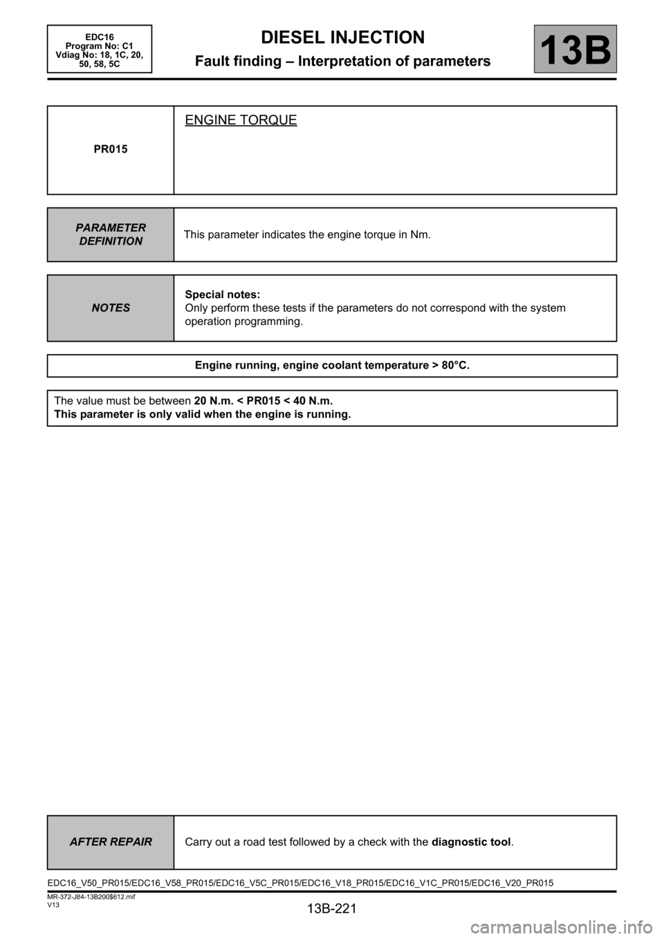
PR015
ENGINE TORQUE
PARAMETER
DEFINITIONThis parameter indicates the engine torque in Nm.
NOTESSpecial notes:
Only perform these tests if the parameters do not correspond with the system
operation programming.
Engine running, engine coolant temperature > 80°C.
The value must be between 20 N.m. < PR015 < 40 N.m.
This parameter is only valid when the engine is running.
AFTER REPAIRCarry out a road test followed by a check with the diagnostic tool.
EDC16_V50_PR015/EDC16_V58_PR015/EDC16_V5C_PR015/EDC16_V18_PR015/EDC16_V1C_PR015/EDC16_V20_PR015