warning lights RENAULT SCENIC 2011 J95 / 3.G Engine And Peripherals EDC16 Workshop Manual
[x] Cancel search | Manufacturer: RENAULT, Model Year: 2011, Model line: SCENIC, Model: RENAULT SCENIC 2011 J95 / 3.GPages: 365, PDF Size: 2.11 MB
Page 13 of 365
13B-13
MR-372-J84-13B200$108.mif
V13
DIESEL INJECTION
Fault finding – System operation
EDC16
Program No: C1
Vdiag No: 18, 1C, 20,
50, 58, 5C
13B
Some vehicles have adopted a sensor for detecting water in the diesel fuel, located in the filter. If there is water in
the diesel fuel, the orange "Injection and pre-post heating" warning light will come on.
The system can inject diesel fuel into the engine at a pressure of up to 1600 bar. Before each operation, check that
the injector rail is depressurised and that the fuel temperature is not too high.
You must respect the cleanliness guidelines and safety advice specified in this document for any work on the high
pressure injection system.
Do not remove the internal parts of the pump and injectors. Only the flow actuator, the diesel temperature sensor
and the Venturi tube can be replaced.
For safety reasons, do not loosen high pressure pipe unions when the engine is running.
It is not possible to remove the pressure sensor from the fuel rail because this may cause circuit contamination
faults. If the pressure sensor fails, the pressure sensor, the rail and the five high pressure pipes must be replaced.
Do not remove an injection pump pulley marked with the number 070 575. If the pump needs to be replaced, replace
the pulley.
Supplying any system component directly with +12V is prohibited.
Ultrasonic decoking and cleaning are prohibited.
Never start the engine unless the battery is connected correctly.
Disconnect the injection computer when carrying out any welding work on the vehicle.
b)The connections between the vehicle's various computers are multiplexed.
The electronic system fitted in this vehicle is multiplexed. This system enables dialogue between the various vehicle
computers. As a result:
– the activation of the fault warning lights on the instrument panel is performed by the multiplex network, with the
vehicle speed sensor on the gearbox deactivated,
– vehicle faults are displayed by the multiplex network,
– the vehicle speed sensor on the gearbox is not needed.
The vehicle speed signal on the instrument panel is transmitted by the ABS computer via a wire connection, then
sent out on the multiplex network by the instrument panel. The vehicle speed signal is used mainly by the injection
computer and the airbag computer.WARNING
The engine must not operate with:
– Diesel fuel containing more than 10% diester.
– petrol, even in tiny quantities.
Page 17 of 365
13B-17
MR-372-J84-13B200$108.mif
V13
DIESEL INJECTION
Fault finding – System operation
EDC16
Program No: C1
Vdiag No: 18, 1C, 20,
50, 58, 5C
13B
If regeneration whilst driving has not been possible, the driver should request After-Sales regeneration in the
following cases:
– the soot weight is greater than 56 g for Vdiag 18.
– the soot weight is greater than 59 g or the number of failed regenerations is greater than 10 for Vdiag 1C
and 20.
This regeneration is carried out in the workshop. It is essential to follow the instructions described in the
interpretation of commands SC017 Particle filter regeneration. To carry out regeneration safely (see Te c h n i c a l
Note 5040A, Recommendations for particle filter regeneration).
Warning light management:
Instrument panel display
The computer manages the data display on the instrument panel relating to engine operation. This involves six
functions:
– the pre-postheating warning light,
– the coolant temperature warning light or warning message;
– the level 1 fault warning light (non-critical fault),
– the level 2 fault warning light (emergency stop),
– the OBD warning light (European On Board Diagnostic),
– particle filter warning message or light.
These six functions are represented by 4 or 5 warning lights and/or messages displayed by the trip computer.
In addition, for vehicles fitted with a voice synthesiser the illumination of some warning lights may be accompanied
by a spoken message (refer to the Driver's Handbook for the vehicle concerned).
A 3 second visual inspection (automatic test procedure managed by the instrument panel) is carried out by the
injection computer when the ignition is switched on.
Orange pre-post heating/non-critical fault SERVICE warning light (level 1)
This light is used both as an in-operation indicator light and as a system fault indicator:
– Continuously lit with + after ignition feed:
Indicates plug preheating (this light goes out when preheating is complete and the engine is able to start).
– Continuously lit accompanied by the message Check injection or Electronic fault:
Indicates a level 1 fault (involving operation of the injection system in defect mode).
The driver should carry out repairs as soon as possible. IMPORTANT
The particle filter must be replaced after a period of time which largely depends on the grade of engine oil used.
This information is provided in the vehicle's Driver's handbook.
After replacing the particle filter, it is essential to reconfigure certain parameters in the computer (see SC036
Reinitialise programming).
Page 18 of 365
13B-18
MR-372-J84-13B200$108.mif
V13
DIESEL INJECTION
Fault finding – System operation
EDC16
Program No: C1
Vdiag No: 18, 1C, 20,
50, 58, 5C
13B
Temperature warning light/red EMERGENCY STOP (level 2)
This indicator light is used both as an in-operation indicator light and as a system fault warning light. It lights up for
3 seconds after the ignition is switched on (automatic test procedure managed by the instrument panel):
– Continuously or intermittently lit, accompanied by the message Engine overheating:
Indicates engine overheating (the driver is free to choose whether or not to stop the vehicle).
–For Vdiag 50, 58 and 5C: continuously lit, accompanied by the message faulty injection:
Indicates a level 2 fault (in this case, the injection is automatically cut after a few seconds).
The driver should carry out repairs as soon as possible.
–For Vdiag 18, 1C and 20: continuously lit, accompanied by the message Injection fault: stop the engine and by
a bleep, this indicates a level 2 fault.
In that case, the vehicle must be stopped immediately (when traffic conditions allow).
The driver should carry out repairs as soon as possible.
ORANGE OBD excess pollution warning light
An engine symbol accompanied by the message Check emission control.
This warning light comes on if the system has one or more OBD faults.
This warning light is used to alert the driver of any injection faults that could lead to excessive pollution, or if the
EOBD system has been deactivated.
The injection computer requests illumination of the OBD warning light for a present fault only after three consecutive
driving cycles.
If it flashes, reduce the engine speed until the flashing stops.
The driver should carry out repairs as soon as possible.
The 3 second visual inspection when the ignition is switched on (automatic test procedure managed by the
instrument panel) is carried out by the injection computer.
Special particle filter ORANGE warning light or warning message (depending on instrument panel)
– Vdiag 50, 58, 5C:
This warning light or message is used to warn the driver that the particle filter is clogged or a significant number of
failed regenerations while driving due to driving conditions not being favourable for regeneration.
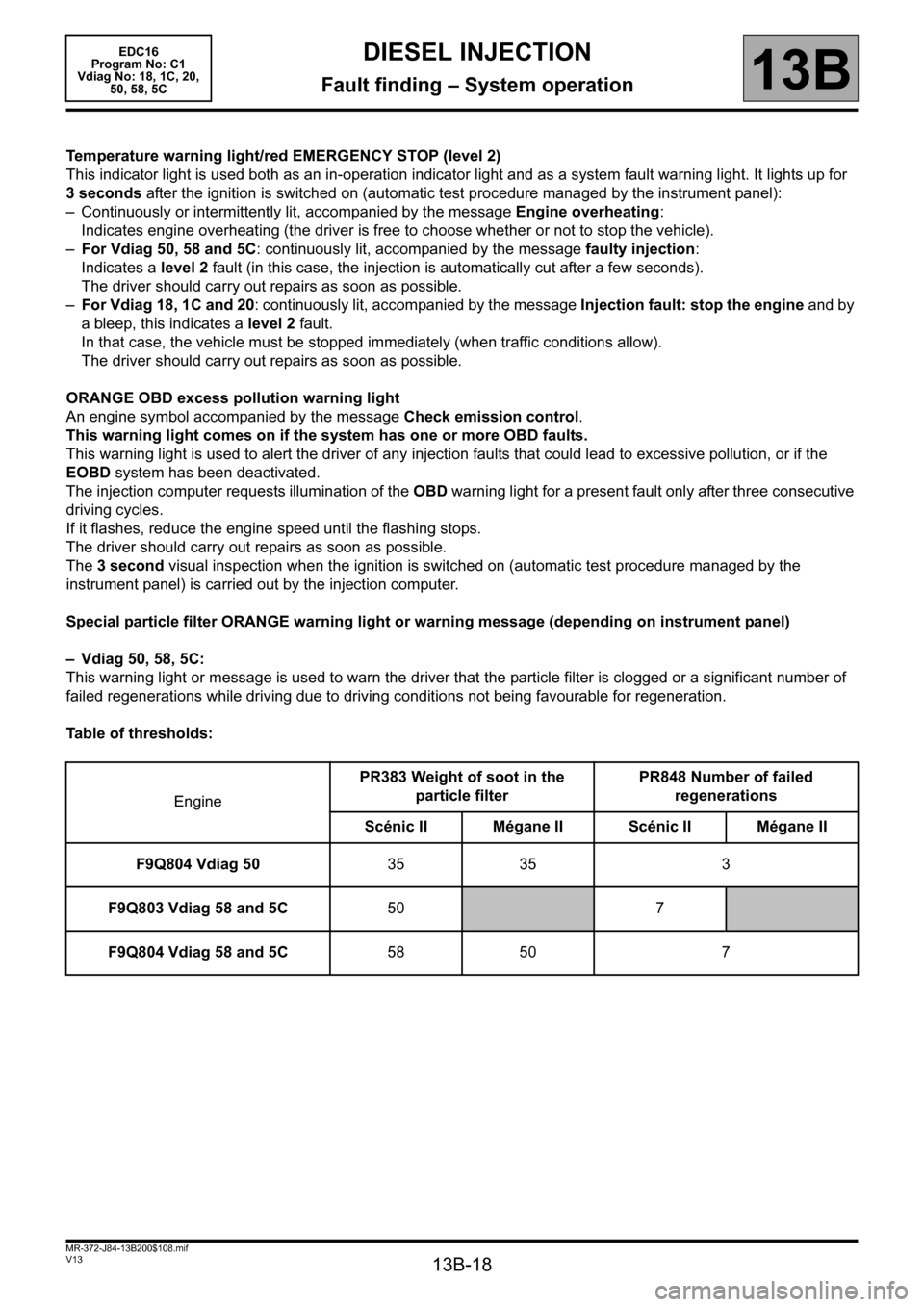
Table of thresholds:
EnginePR383 Weight of soot in the
particle filterPR848 Number of failed
regenerations
Scénic II Mégane IIScénic II Mégane II
F9Q804 Vdiag 5035 35 3
F9Q803 Vdiag 58 and 5C50
7
F9Q804 Vdiag 58 and 5C58 50 7
Page 27 of 365
13B-27
MR-372-J84-13B200$216.mif
V13
13B
DIESEL INJECTION
Fault finding – Fault summary table
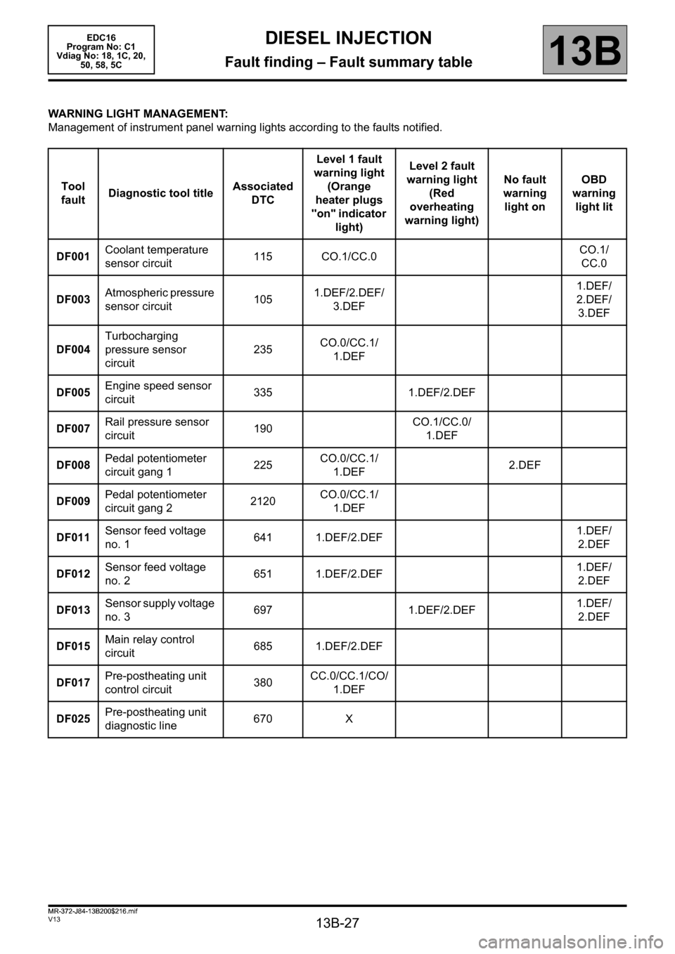
WARNING LIGHT MANAGEMENT:
Management of instrument panel warning lights according to the faults notified.
Tool
faultDiagnostic tool titleAssociated
DTCLevel 1 fault
warning light
(Orange
heater plugs
"on" indicator
light)Level 2 fault
warning light
(Red
overheating
warning light)No fault
warning
light onOBD
warning
light lit
DF001Coolant temperature
sensor circuit115 CO.1/CC.0CO.1/
CC.0
DF003Atmospheric pressure
sensor circuit1051.DEF/2.DEF/
3.DEF1.DEF/
2.DEF/
3.DEF
DF004Turbocharging
pressure sensor
circuit235CO.0/CC.1/
1.DEF
DF005Engine speed sensor
circuit335 1.DEF/2.DEF
DF007Rail pressure sensor
circuit190CO.1/CC.0/
1.DEF
DF008Pedal potentiometer
circuit gang 1225CO.0/CC.1/
1.DEF2.DEF
DF009Pedal potentiometer
circuit gang 22120CO.0/CC.1/
1.DEF
DF011Sensor feed voltage
no. 1641 1.DEF/2.DEF1.DEF/
2.DEF
DF012Sensor feed voltage
no. 2651 1.DEF/2.DEF1.DEF/
2.DEF
DF013Sensor supply voltage
no. 3697 1.DEF/2.DEF1.DEF/
2.DEF
DF015Main relay control
circuit685 1.DEF/2.DEF
DF017Pre-postheating unit
control circuit380CC.0/CC.1/CO/
1.DEF
DF025Pre-postheating unit
diagnostic line670 X
EDC16
Program No: C1
Vdiag No: 18, 1C, 20,
50, 58, 5C
MR-372-J84-13B200$216.mif
Page 335 of 365
13B-335
MR-372-J84-13B200$828.mif
V13
DIESEL INJECTION
Fault finding – Fault Finding Chart
EDC16
Program No.: C1
Vdiag no.: 18, 1C, 20,
50, 58, 5C
13B
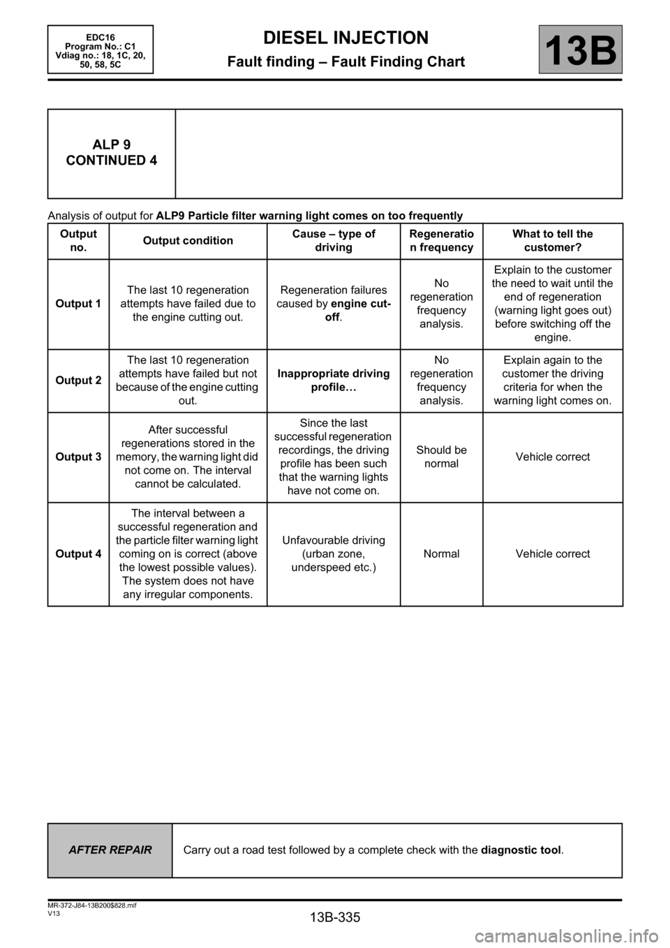
Analysis of output for ALP9 Particle filter warning light comes on too frequently
ALP 9
CONTINUED 4
Output
no. Output conditionCause – type of
drivingRegeneratio
n frequencyWhat to tell the
customer?
Output 1The last 10 regeneration
attempts have failed due to
the engine cutting out.Regeneration failures
caused by engine cut-
off.No
regeneration
frequency
analysis.Explain to the customer
the need to wait until the
end of regeneration
(warning light goes out)
before switching off the
engine.
Output 2The last 10 regeneration
attempts have failed but not
because of the engine cutting
out.Inappropriate driving
profile…No
regeneration
frequency
analysis.Explain again to the
customer the driving
criteria for when the
warning light comes on.
Output 3After successful
regenerations stored in the
memory, the warning light did
not come on. The interval
cannot be calculated.Since the last
successful regeneration
recordings, the driving
profile has been such
that the warning lights
have not come on.Should be
normalVehicle correct
Output 4The interval between a
successful regeneration and
the particle filter warning light
coming on is correct (above
the lowest possible values).
The system does not have
any irregular components.Unfavourable driving
(urban zone,
underspeed etc.)Normal Vehicle correct
AFTER REPAIRCarry out a road test followed by a complete check with the diagnostic tool.