engine coolant RENAULT SCENIC 2011 J95 / 3.G Engine And Peripherals EDC16C36 Workshop Manual
[x] Cancel search | Manufacturer: RENAULT, Model Year: 2011, Model line: SCENIC, Model: RENAULT SCENIC 2011 J95 / 3.GPages: 431, PDF Size: 2.03 MB
Page 345 of 431
13B-345V9 MR-372-J84-13B450$152.mif
DIESEL INJECTION
Fault finding – Interpretation of parameters13B
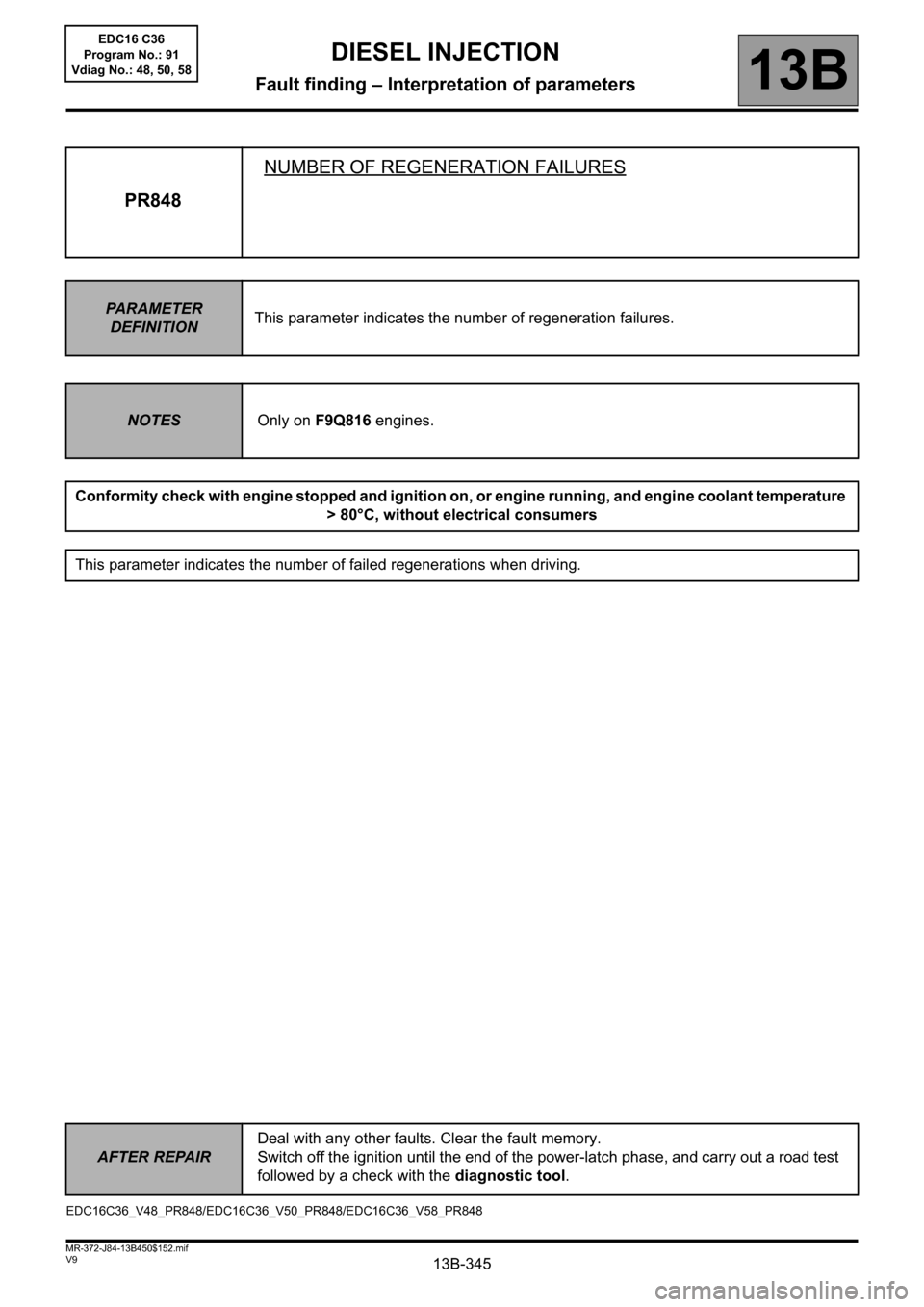
PR848NUMBER OF REGENERATION FAILURES
PARAMETER
DEFINITIONThis parameter indicates the number of regeneration failures.
NOTESOnly on F9Q816 engines.
Conformity check with engine stopped and ignition on, or engine running, and engine coolant temperature
> 80°C, without electrical consumers
This parameter indicates the number of failed regenerations when driving.
EDC16C36_V48_PR848/EDC16C36_V50_PR848/EDC16C36_V58_PR848
AFTER REPAIRDeal with any other faults. Clear the fault memory.
Switch off the ignition until the end of the power-latch phase, and carry out a road test
followed by a check with the diagnostic tool.
EDC16 C36
Program No.: 91
Vdiag No.: 48, 50, 58
Page 346 of 431
13B-346V9 MR-372-J84-13B450$152.mif
DIESEL INJECTION
Fault finding – Interpretation of parameters13B
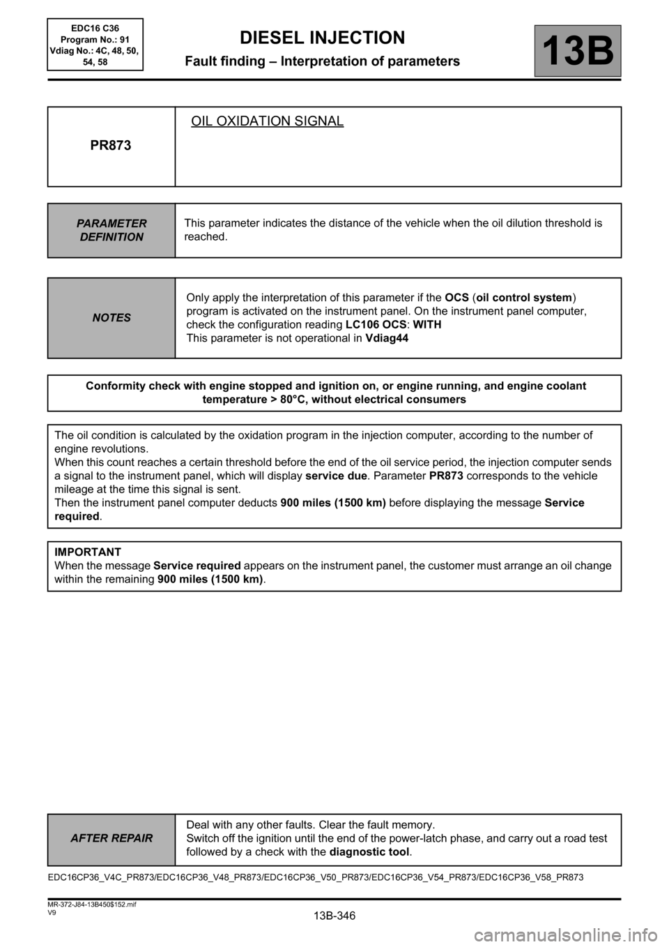
PR873OIL OXIDATION SIGNAL
PARAMETER
DEFINITIONThis parameter indicates the distance of the vehicle when the oil dilution threshold is
reached.
NOTESOnly apply the interpretation of this parameter if the OCS (oil control system)
program is activated on the instrument panel. On the instrument panel computer,
check the configuration reading LC106 OCS: WITH
This parameter is not operational in Vdiag44
Conformity check with engine stopped and ignition on, or engine running, and engine coolant
temperature > 80°C, without electrical consumers
The oil condition is calculated by the oxidation program in the injection computer, according to the number of
engine revolutions.
When this count reaches a certain threshold before the end of the oil service period, the injection computer sends
a signal to the instrument panel, which will display service due. Parameter PR873 corresponds to the vehicle
mileage at the time this signal is sent.
Then the instrument panel computer deducts 900 miles (1500 km) before displaying the message Service
required.
IMPORTANT
When the message Service required appears on the instrument panel, the customer must arrange an oil change
within the remaining 900 miles (1500 km).
EDC16CP36_V4C_PR873/EDC16CP36_V48_PR873/EDC16CP36_V50_PR873/EDC16CP36_V54_PR873/EDC16CP36_V58_PR873
AFTER REPAIRDeal with any other faults. Clear the fault memory.
Switch off the ignition until the end of the power-latch phase, and carry out a road test
followed by a check with the diagnostic tool.
EDC16 C36
Program No.: 91
Vdiag No.: 4C, 48, 50,
54, 58
Page 348 of 431
13B-348V9 MR-372-J84-13B450$152.mif
DIESEL INJECTION
Fault finding – Interpretation of parameters13B
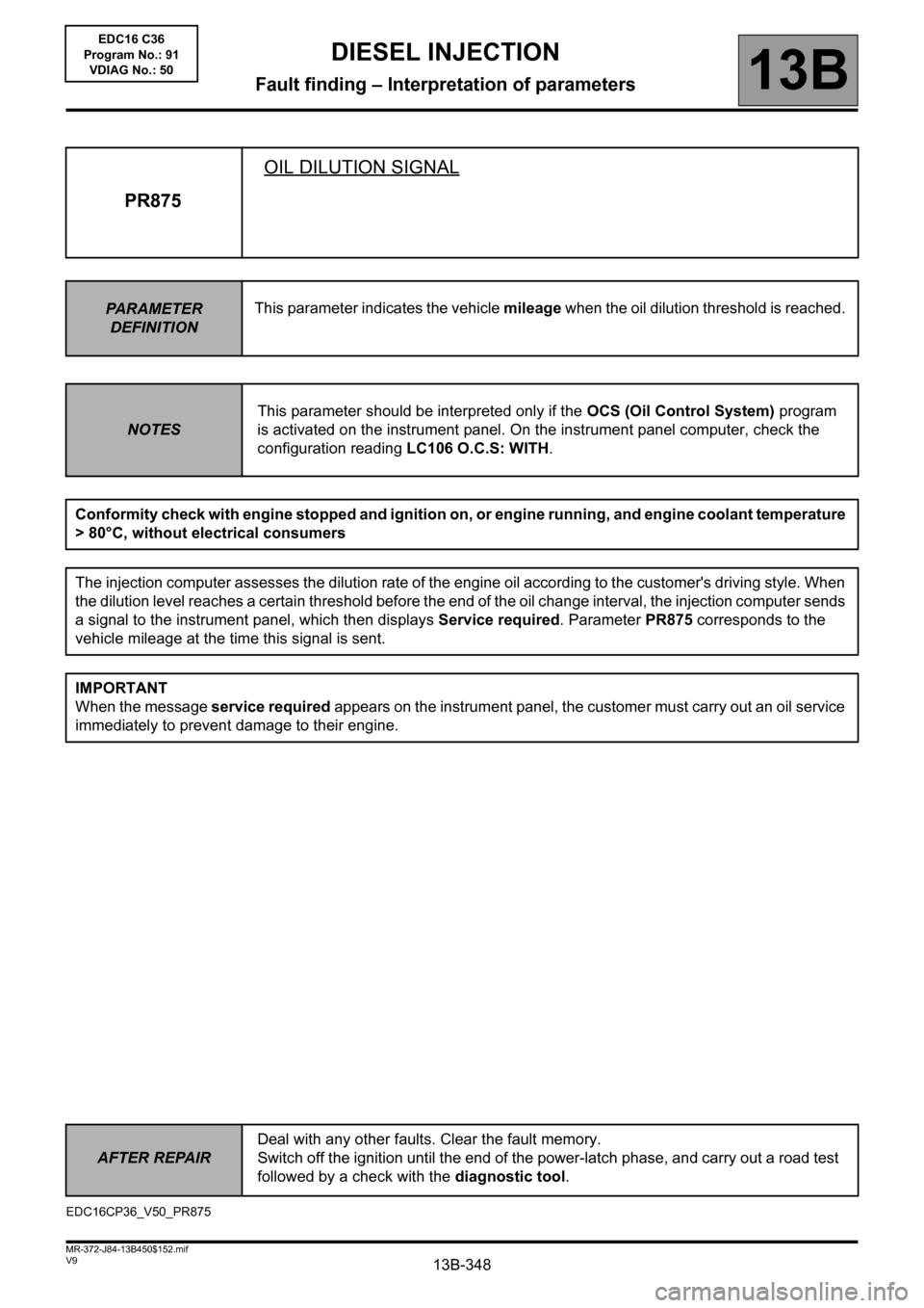
PR875OIL DILUTION SIGNAL
PARAMETER
DEFINITIONThis parameter indicates the vehicle mileage when the oil dilution threshold is reached.
NOTESThis parameter should be interpreted only if the OCS (Oil Control System) program
is activated on the instrument panel. On the instrument panel computer, check the
configuration reading LC106 O.C.S: WITH.
Conformity check with engine stopped and ignition on, or engine running, and engine coolant temperature
> 80°C, without electrical consumers
The injection computer assesses the dilution rate of the engine oil according to the customer's driving style. When
the dilution level reaches a certain threshold before the end of the oil change interval, the injection computer sends
a signal to the instrument panel, which then displays Service required. Parameter PR875 corresponds to the
vehicle mileage at the time this signal is sent.
IMPORTANT
When the message service required appears on the instrument panel, the customer must carry out an oil service
immediately to prevent damage to their engine.
EDC16CP36_V50_PR875EDC16 C36
Program No.: 91
VDIAG No.: 50
AFTER REPAIRDeal with any other faults. Clear the fault memory.
Switch off the ignition until the end of the power-latch phase, and carry out a road test
followed by a check with the diagnostic tool.
Page 349 of 431
13B-349V9 MR-372-J84-13B450$152.mif
DIESEL INJECTION
Fault finding – Interpretation of parameters13B
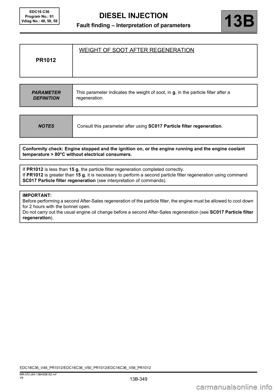
PR1012WEIGHT OF SOOT AFTER REGENERATION
PARAMETER
DEFINITIONThis parameter indicates the weight of soot, in g, in the particle filter after a
regeneration.
NOTESConsult this parameter after using SC017 Particle filter regeneration.
Conformity check: Engine stopped and the ignition on, or the engine running and the engine coolant
temperature > 80°C without electrical consumers.
If PR1012 is less than 15 g, the particle filter regeneration completed correctly.
If PR1012 is greater than 15 g, it is necessary to perform a second particle filter regeneration using command
SC017 Particle filter regeneration (see interpretation of commands).
IMPORTANT:
Before performing a second After-Sales regeneration of the particle filter, the engine must be allowed to cool down
for 2 hours with the bonnet open.
Do not carry out the usual engine oil change before a second After-Sales regeneration (see SC017 Particle filter
regeneration).
EDC16C36_V48_PR1012/EDC16C36_V50_PR1012/EDC16C36_V58_PR1012EDC16 C36
Program No.: 91
Vdiag No.: 48, 50, 58
Page 356 of 431
13B-356
AFTER REPAIRRepeat the conformity check in the interpretation of statuses and parameters
V9 MR-372-J84-13B450$170.mif
DIESEL INJECTION
Fault finding – Interpretation of commands13B
SC017
CONTINUED 1
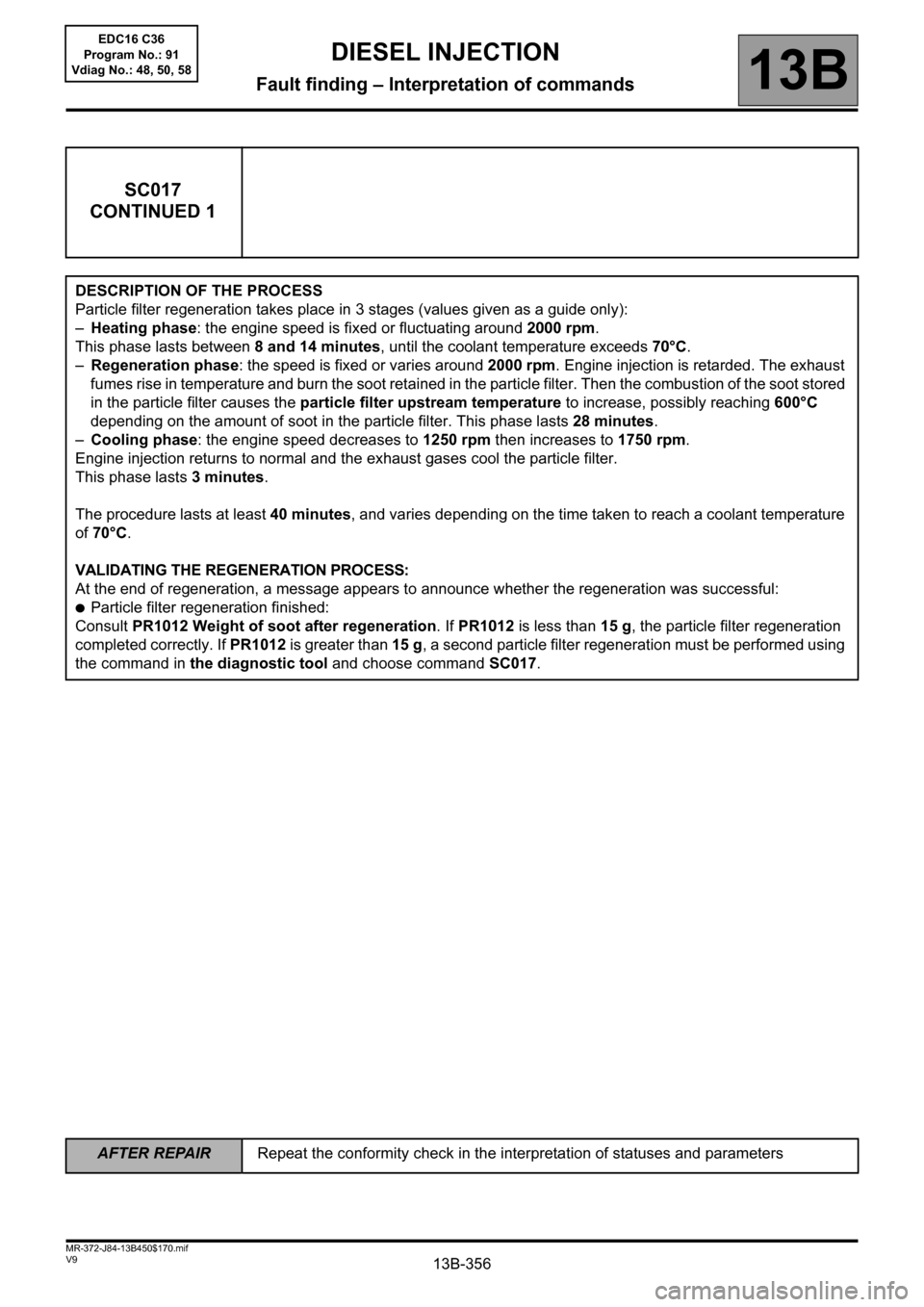
DESCRIPTION OF THE PROCESS
Particle filter regeneration takes place in 3 stages (values given as a guide only):
–Heating phase: the engine speed is fixed or fluctuating around 2000 rpm.
This phase lasts between 8 and 14 minutes, until the coolant temperature exceeds 70°C.
–Regeneration phase: the speed is fixed or varies around 2000 rpm. Engine injection is retarded. The exhaust
fumes rise in temperature and burn the soot retained in the particle filter. Then the combustion of the soot stored
in the particle filter causes the particle filter upstream temperature to increase, possibly reaching 600°C
depending on the amount of soot in the particle filter. This phase lasts 28 minutes.
–Cooling phase: the engine speed decreases to 1250 rpm then increases to 1750 rpm.
Engine injection returns to normal and the exhaust gases cool the particle filter.
This phase lasts 3 minutes.
The procedure lasts at least 40 minutes, and varies depending on the time taken to reach a coolant temperature
of 70°C.
VALIDATING THE REGENERATION PROCESS:
At the end of regeneration, a message appears to announce whether the regeneration was successful:
●Particle filter regeneration finished:
Consult PR1012 Weight of soot after regeneration. If PR1012 is less than 15 g, the particle filter regeneration
completed correctly. If PR1012 is greater than 15 g, a second particle filter regeneration must be performed using
the command in the diagnostic tool and choose command SC017.
EDC16 C36
Program No.: 91
Vdiag No.: 48, 50, 58
Page 384 of 431
13B-384
AFTER REPAIRCarry out a road test followed by a complete check with the diagnostic tool.
V9 MR-372-J84-13B450$190.mif
DIESEL INJECTION
Fault finding – Fault Finding Chart13B
ALP2
CONTINUED 1
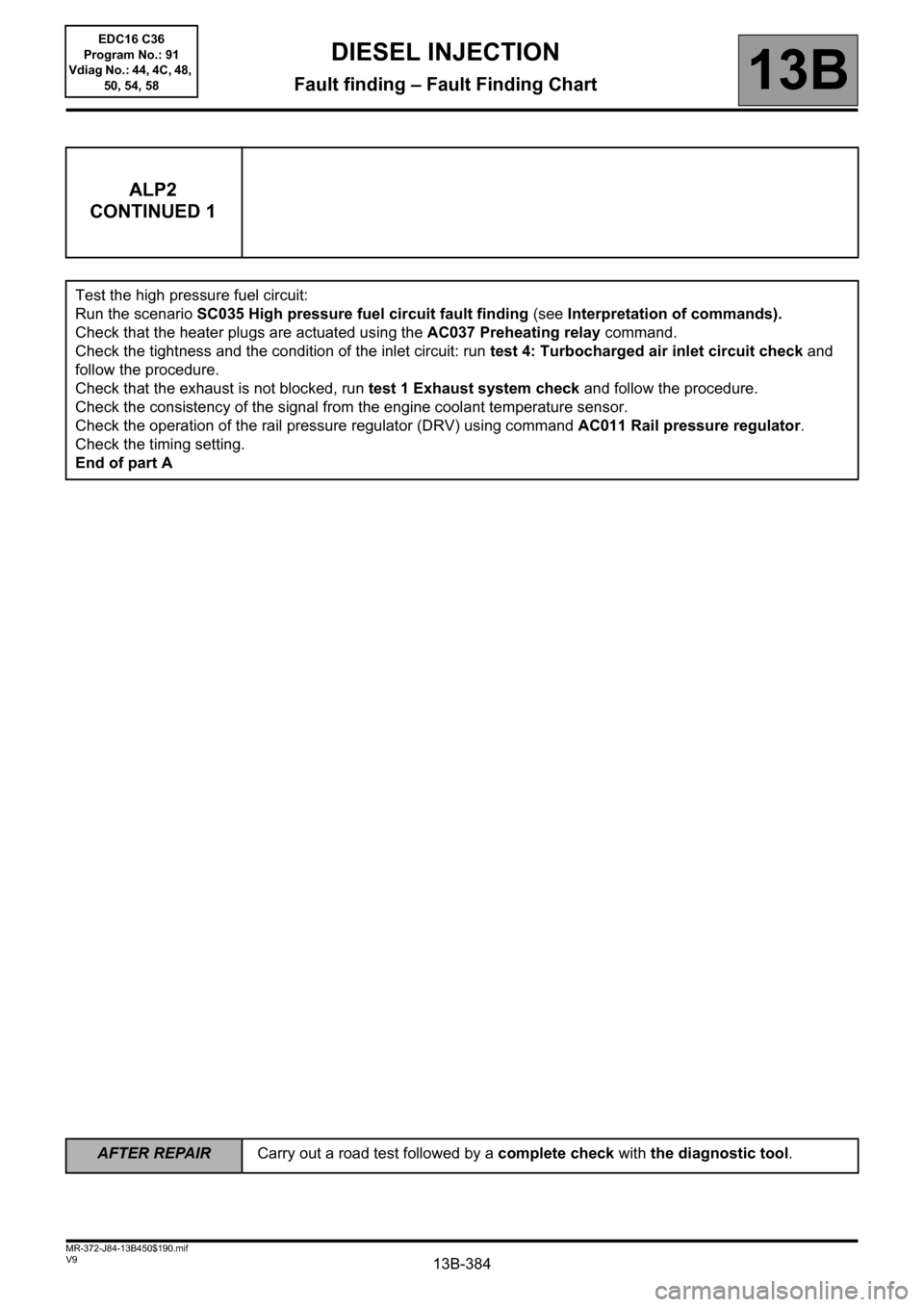
Test the high pressure fuel circuit:
Run the scenario SC035 High pressure fuel circuit fault finding (see Interpretation of commands).
Check that the heater plugs are actuated using the AC037 Preheating relay command.
Check the tightness and the condition of the inlet circuit: run test 4: Turbocharged air inlet circuit check and
follow the procedure.
Check that the exhaust is not blocked, run test 1 Exhaust system check and follow the procedure.
Check the consistency of the signal from the engine coolant temperature sensor.
Check the operation of the rail pressure regulator (DRV) using command AC011 Rail pressure regulator.
Check the timing setting.
End of part A
EDC16 C36
Program No.: 91
Vdiag No.: 44, 4C, 48,
50, 54, 58
Page 387 of 431
13B-387
AFTER REPAIRCarry out a road test followed by a complete check with the diagnostic tool.
V9 MR-372-J84-13B450$190.mif
DIESEL INJECTION
Fault finding – Fault Finding Chart13B
ALP4
CONTINUED
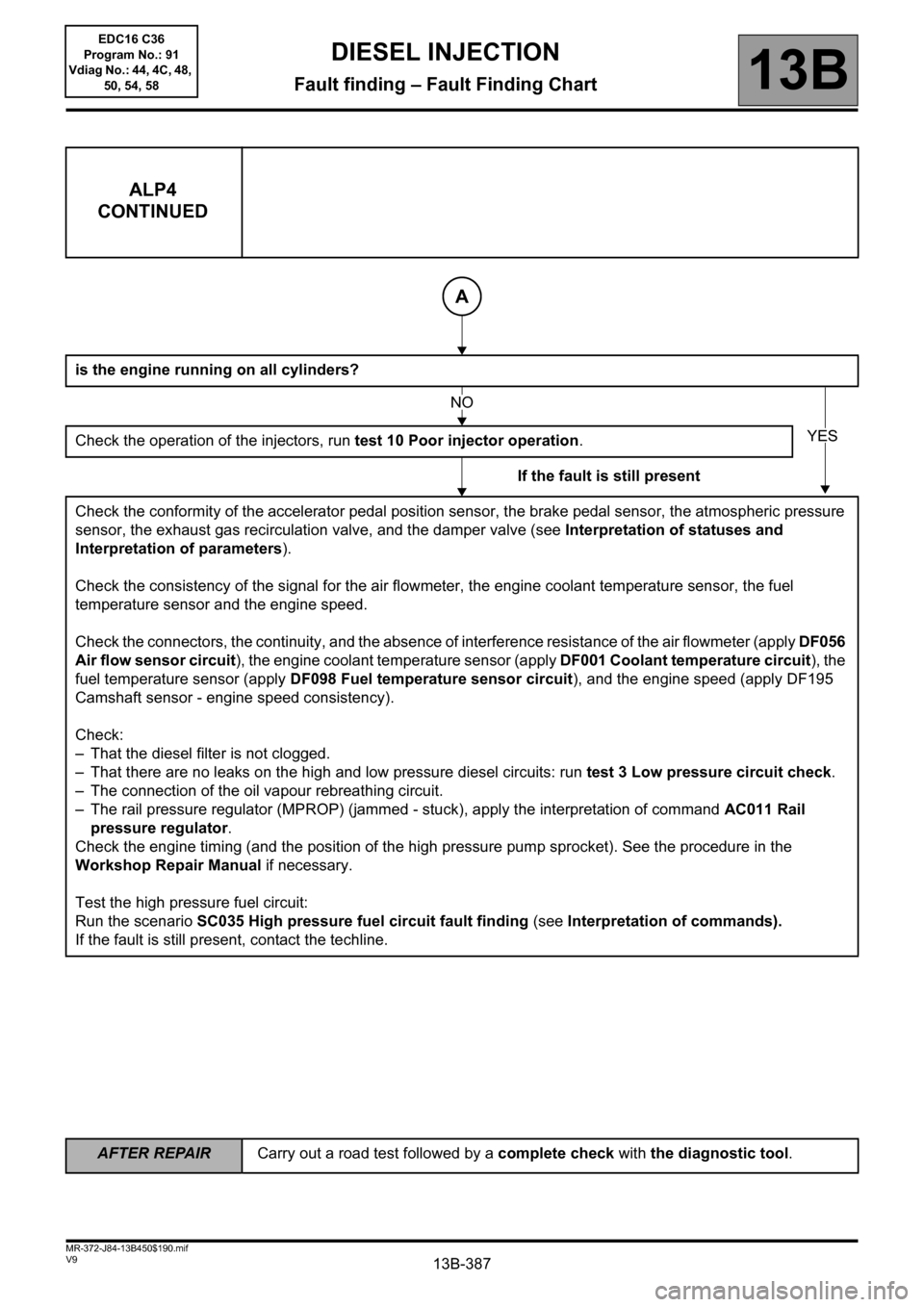
is the engine running on all cylinders?
Check the operation of the injectors, run test 10 Poor injector operation.
If the fault is still present
Check the conformity of the accelerator pedal position sensor, the brake pedal sensor, the atmospheric pressure
sensor, the exhaust gas recirculation valve, and the damper valve (see Interpretation of statuses and
Interpretation of parameters).
Check the consistency of the signal for the air flowmeter, the engine coolant temperature sensor, the fuel
temperature sensor and the engine speed.
Check the connectors, the continuity, and the absence of interference resistance of the air flowmeter (apply DF056
Air flow sensor circuit), the engine coolant temperature sensor (apply DF001 Coolant temperature circuit), the
fuel temperature sensor (apply DF098 Fuel temperature sensor circuit), and the engine speed (apply DF195
Camshaft sensor - engine speed consistency).
Check:
– That the diesel filter is not clogged.
– That there are no leaks on the high and low pressure diesel circuits: run test 3 Low pressure circuit check.
– The connection of the oil vapour rebreathing circuit.
– The rail pressure regulator (MPROP) (jammed - stuck), apply the interpretation of command AC011 Rail
pressure regulator.
Check the engine timing (and the position of the high pressure pump sprocket). See the procedure in the
Workshop Repair Manual if necessary.
Test the high pressure fuel circuit:
Run the scenario SC035 High pressure fuel circuit fault finding (see Interpretation of commands).
If the fault is still present, contact the techline.
A
NO
YES
EDC16 C36
Program No.: 91
Vdiag No.: 44, 4C, 48,
50, 54, 58
Page 412 of 431
13B-412V9 MR-372-J84-13B450$200.mif
DIESEL INJECTION
Fault finding – Tests13B
* OCR: Opening Cyclic Ratio
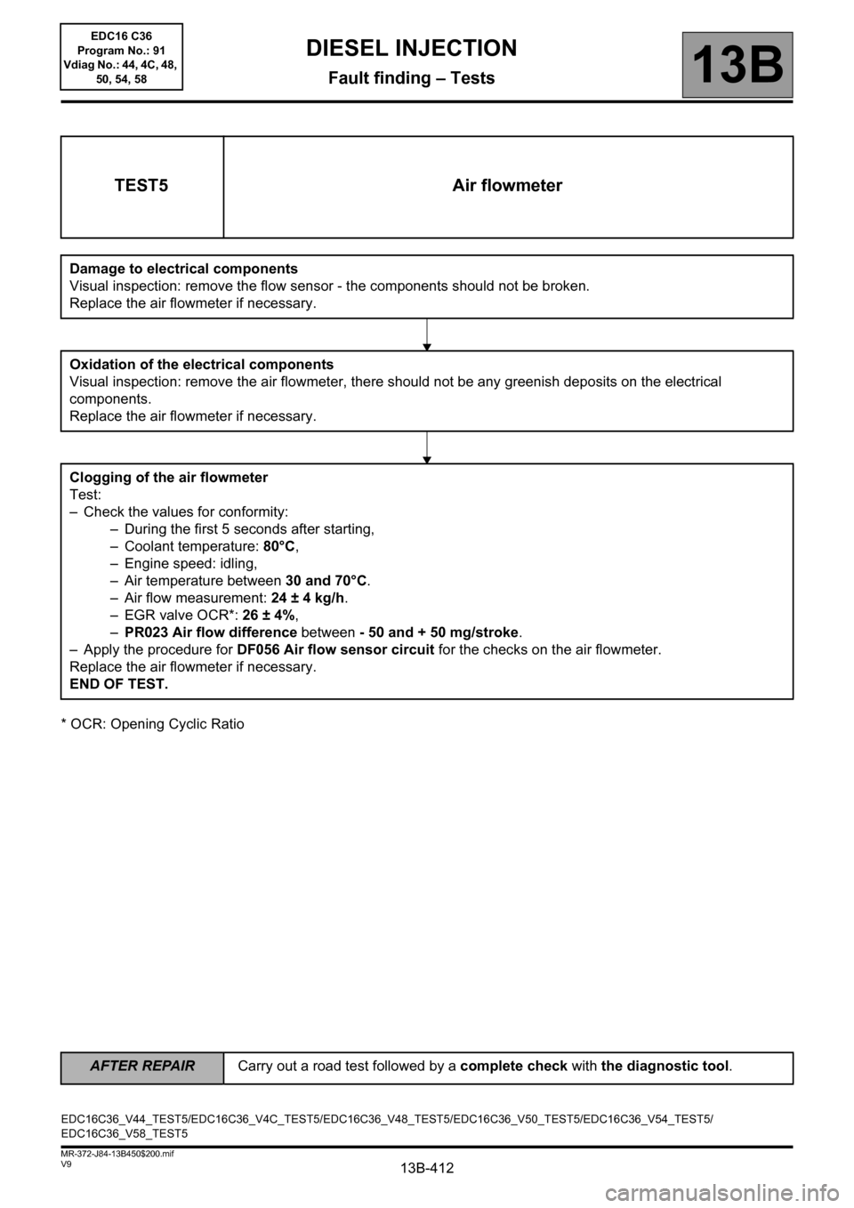
TEST5 Air flowmeter
Damage to electrical components
Visual inspection: remove the flow sensor - the components should not be broken.
Replace the air flowmeter if necessary.
Oxidation of the electrical components
Visual inspection: remove the air flowmeter, there should not be any greenish deposits on the electrical
components.
Replace the air flowmeter if necessary.
Clogging of the air flowmeter
Test:
– Check the values for conformity:
– During the first 5 seconds after starting,
– Coolant temperature: 80°C,
– Engine speed: idling,
– Air temperature between 30 and 70°C.
– Air flow measurement: 24 ± 4 kg/h.
– EGR valve OCR*: 26 ± 4%,
–PR023 Air flow difference between - 50 and + 50 mg/stroke.
– Apply the procedure for DF056 Air flow sensor circuit for the checks on the air flowmeter.
Replace the air flowmeter if necessary.
END OF TEST.
EDC16C36_V44_TEST5/EDC16C36_V4C_TEST5/EDC16C36_V48_TEST5/EDC16C36_V50_TEST5/EDC16C36_V54_TEST5/
EDC16C36_V58_TEST5
AFTER REPAIRCarry out a road test followed by a complete check with the diagnostic tool.
EDC16 C36
Program No.: 91
Vdiag No.: 44, 4C, 48,
50, 54, 58
Page 429 of 431
13B-429V9 MR-372-J84-13B450$200.mif
DIESEL INJECTION
Fault finding – Tests13B
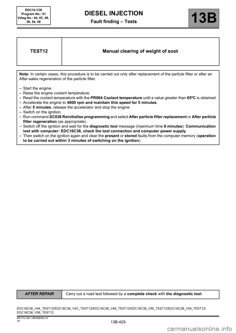
TEST12 Manual clearing of weight of soot
Note: In certain cases, this procedure is to be carried out only after replacement of the particle filter or after an
After-sales regeneration of the particle filter.
– Start the engine.
– Raise the engine coolant temperature.
– Read the coolant temperature with the PR064 Coolant temperature until a value greater than 65ºC is obtained.
– Accelerate the engine to 4000 rpm and maintain this speed for 5 minutes.
–After 5 minutes, release the accelerator and stop the engine.
– Switch on the ignition.
– Run command SC036 Reinitialise programming and select After particle filter replacement or After particle
filter regeneration (as appropriate).
– Switch off the ignition and wait for the diagnostic tool message (maximum time 8 minutes): Communication
lost with computer: EDC16C36, check the tool connection and computer power supply.
– Then switch on the ignition again and clear the present or stored faults from the computer memory (operation
to be carried out within 3 minutes of switching on the ignition).
EDC16C36_V44_TEST12/EDC16C36_V4C_TEST12/EDC16C36_V48_TEST12/EDC16C36_V50_TEST12/EDC16C36_V54_TEST12/
EDC16C36_V58_TEST12EDC16 C36
Program No.: 91
Vdiag No.: 44, 4C, 48,
50, 54, 58
AFTER REPAIRCarry out a road test followed by a complete check with the diagnostic tool.