wiring RENAULT SCENIC 2011 J95 / 3.G Engine And Peripherals EDC16C36 Workshop Manual
[x] Cancel search | Manufacturer: RENAULT, Model Year: 2011, Model line: SCENIC, Model: RENAULT SCENIC 2011 J95 / 3.GPages: 431, PDF Size: 2.03 MB
Page 253 of 431
13B-253V9 MR-372-J84-13B450$132.mif
DIESEL INJECTION
Fault finding – Interpretation of statuses13B
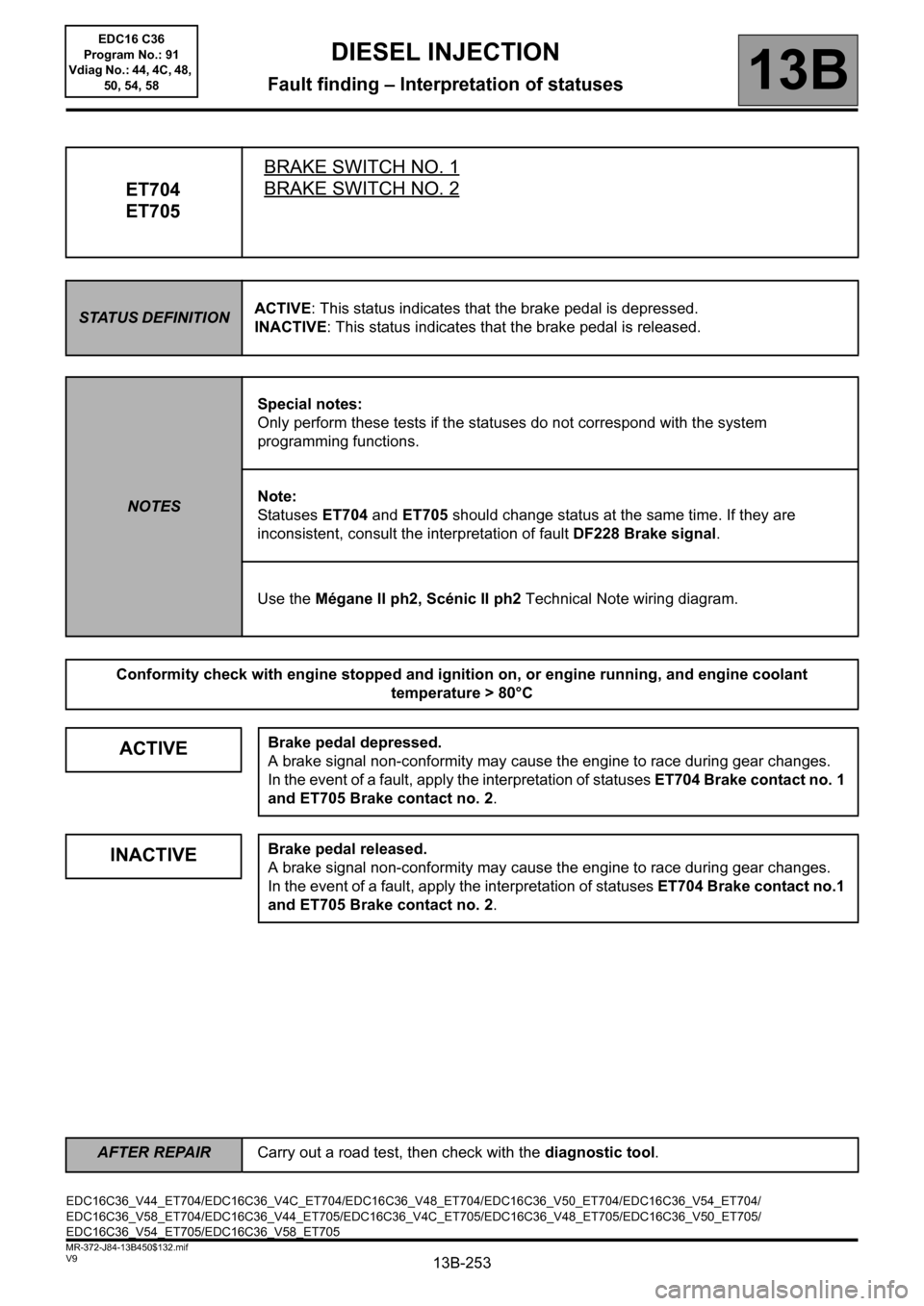
ET704
ET705BRAKE SWITCH NO. 1BRAKE SWITCH NO. 2
STATUS DEFINITIONACTIVE: This status indicates that the brake pedal is depressed.
INACTIVE: This status indicates that the brake pedal is released.
NOTESSpecial notes:
Only perform these tests if the statuses do not correspond with the system
programming functions.
Note:
Statuses ET704 and ET705 should change status at the same time. If they are
inconsistent, consult the interpretation of fault DF228 Brake signal.
Use the Mégane II ph2, Scénic II ph2 Technical Note wiring diagram.
Conformity check with engine stopped and ignition on, or engine running, and engine coolant
temperature > 80°C
ACTIVEBrake pedal depressed.
A brake signal non-conformity may cause the engine to race during gear changes.
In the event of a fault, apply the interpretation of statuses ET704 Brake contact no. 1
and ET705 Brake contact no. 2.
INACTIVEBrake pedal released.
A brake signal non-conformity may cause the engine to race during gear changes.
In the event of a fault, apply the interpretation of statuses ET704 Brake contact no.1
and ET705 Brake contact no. 2.
EDC16C36_V44_ET704/EDC16C36_V4C_ET704/EDC16C36_V48_ET704/EDC16C36_V50_ET704/EDC16C36_V54_ET704/
EDC16C36_V58_ET704/EDC16C36_V44_ET705/EDC16C36_V4C_ET705/EDC16C36_V48_ET705/EDC16C36_V50_ET705/
EDC16C36_V54_ET705/EDC16C36_V58_ET705
AFTER REPAIRCarry out a road test, then check with the diagnostic tool.
EDC16 C36
Program No.: 91
Vdiag No.: 44, 4C, 48,
50, 54, 58
Page 254 of 431

13B-254V9 MR-372-J84-13B450$132.mif
DIESEL INJECTION
Fault finding – Interpretation of statuses13B
ET704
ET705
CONTINUED
Sensor electrical conformity
ACTIVE
or
INACTIVEIf the brake lights are working:
check the continuity and the absence of interference resistance on the following
connection:
– Connection code 5A between components 160 and 120/645/119.
If there is a repair procedure (see Technical Note 6015A, Repairing electrical
wiring, Wiring: Precautions for repair) repair the wiring, otherwise replace it.
If the brake lights are not operational, check:
– the condition and fitting of the brake switch,
– the status and conformity of the fuse for the brake lights.
– the conformity of the values in the following table:
Disconnect the switch and carry out the following checks:
for MEGANE II and SCENIC II with ESP
Continuity between
connectionsInsulation between
connections
Switch engaged
(Brake pedal released)5A and BPT 65G and SP17
Switch released
(Brake pedal
depressed)65G and SP17 5A and BPT
Replace the switch if the values obtained are not correct.
For MEGANE II and SCENIC II without ESP
Continuity between
connectionsInsulation between
connections
Switch engaged
(Brake pedal released)5A and BPT 65A and SP17
Switch released
(Brake pedal
depressed)65A and SP17 5A and BPT
Replace the switch if the values obtained are not correct.
AFTER REPAIRCarry out a road test, then check with the diagnostic tool.
EDC16 C36
Program No.: 91
Vdiag No.: 44, 4C, 48,
50, 54, 58
Page 272 of 431
13B-272
AFTER REPAIRCarry out a road test, then check with the diagnostic tool.
V9 MR-372-J84-13B450$151.mif
DIESEL INJECTION
Fault finding – Interpretation of parameters13B
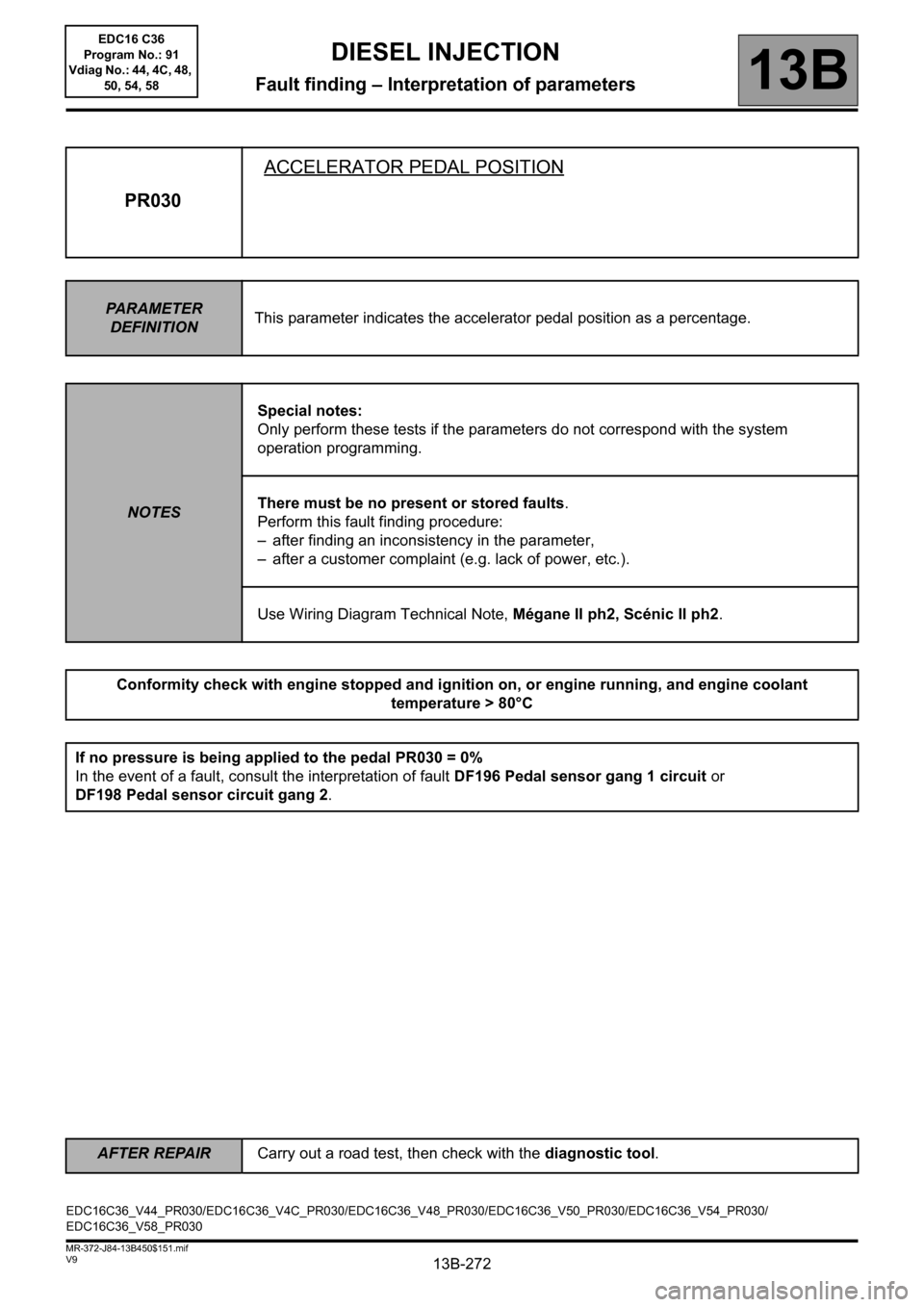
PR030ACCELERATOR PEDAL POSITION
PARAMETER
DEFINITIONThis parameter indicates the accelerator pedal position as a percentage.
NOTESSpecial notes:
Only perform these tests if the parameters do not correspond with the system
operation programming.
There must be no present or stored faults.
Perform this fault finding procedure:
– after finding an inconsistency in the parameter,
– after a customer complaint (e.g. lack of power, etc.).
Use Wiring Diagram Technical Note, Mégane II ph2, Scénic II ph2.
Conformity check with engine stopped and ignition on, or engine running, and engine coolant
temperature > 80°C
If no pressure is being applied to the pedal PR030 = 0%
In the event of a fault, consult the interpretation of fault DF196 Pedal sensor gang 1 circuit or
DF198 Pedal sensor circuit gang 2.
EDC16C36_V44_PR030/EDC16C36_V4C_PR030/EDC16C36_V48_PR030/EDC16C36_V50_PR030/EDC16C36_V54_PR030/
EDC16C36_V58_PR030EDC16 C36
Program No.: 91
Vdiag No.: 44, 4C, 48,
50, 54, 58
Page 273 of 431

13B-273
AFTER REPAIRCarry out a road test, then check with the diagnostic tool.
V9 MR-372-J84-13B450$151.mif
DIESEL INJECTION
Fault finding – Interpretation of parameters13B
PR030
CONTINUED
Sensor electrical conformity
Check the continuity and the absence of interference resistance of the following connections:
– Connection code 3LR,
– Connection code 3LS,
– Connection code 3LT,
– Connection code 3LU,
– Connection code 3LW,
– Connection code 3LV,
between components 120 and 921.
If any of the connections are faulty and there is a repair method (see Technical Note 6015A, Electrical wiring
repair, Wiring: precautions for repairs), repair the wiring; otherwise replace the wiring.
Pedal sensor connected, vehicle with the ignition on and the engine stopped:
– check that the value of PR030 Accelerator pedal position:
0% no load,
100% full load,
138% full load after kickdown point on pedal.
– if the value is not correct, replace the pedal sensor.
EDC16 C36
Program No.: 91
Vdiag No.: 44, 4C, 48,
50, 54, 58
Page 276 of 431
13B-276
AFTER REPAIRCarry out a road test, then check with the diagnostic tool.
V9 MR-372-J84-13B450$151.mif
DIESEL INJECTION
Fault finding – Interpretation of parameters13B
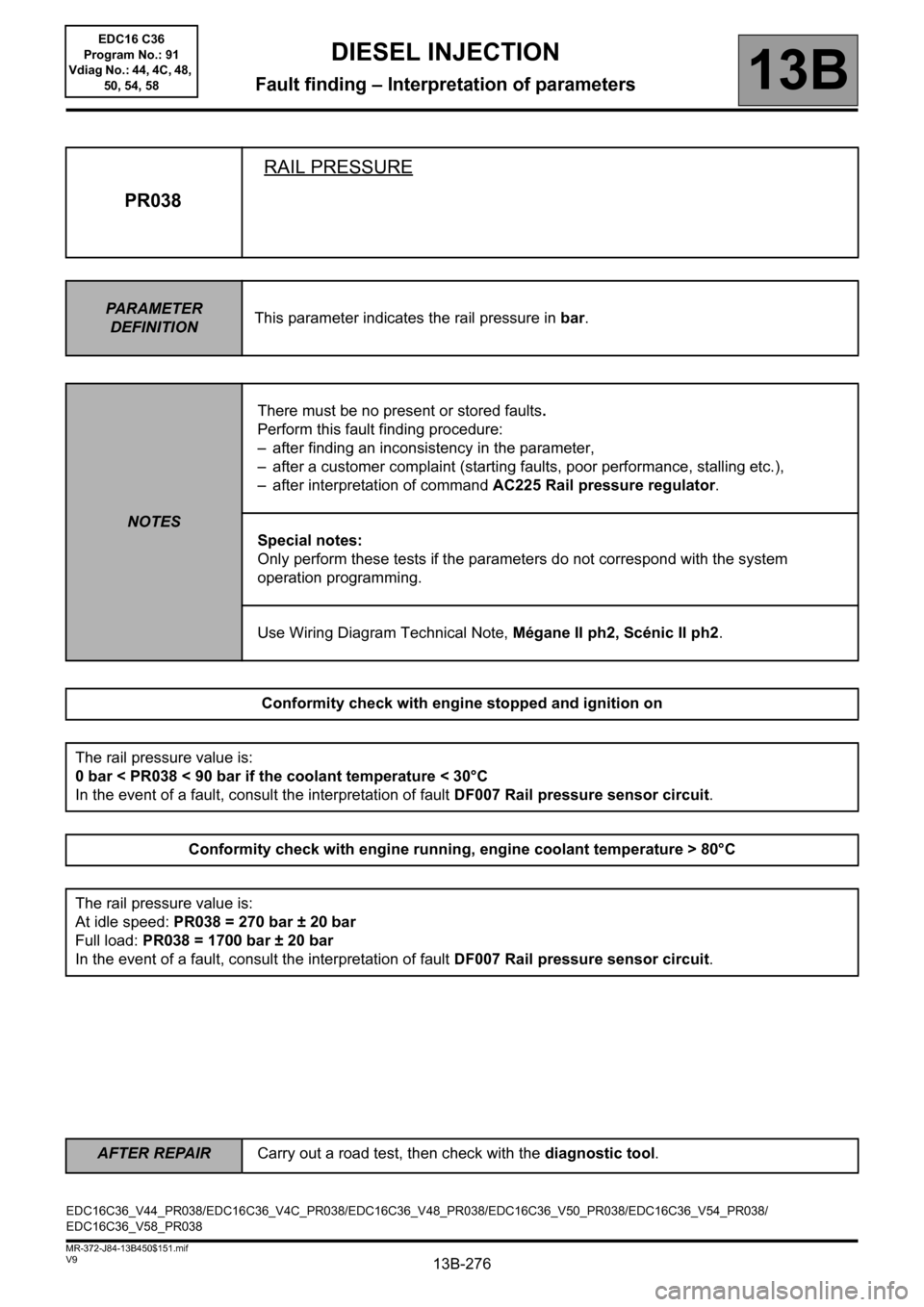
PR038RAIL PRESSURE
PARAMETER
DEFINITIONThis parameter indicates the rail pressure in bar.
NOTESThere must be no present or stored faults.
Perform this fault finding procedure:
– after finding an inconsistency in the parameter,
– after a customer complaint (starting faults, poor performance, stalling etc.),
– after interpretation of command AC225 Rail pressure regulator.
Special notes:
Only perform these tests if the parameters do not correspond with the system
operation programming.
Use Wiring Diagram Technical Note, Mégane II ph2, Scénic II ph2.
Conformity check with engine stopped and ignition on
The rail pressure value is:
0 bar < PR038 < 90 bar if the coolant temperature < 30°C
In the event of a fault, consult the interpretation of fault DF007 Rail pressure sensor circuit.
Conformity check with engine running, engine coolant temperature > 80°C
The rail pressure value is:
At idle speed: PR038 = 270 bar ± 20 bar
Full load: PR038 = 1700 bar ± 20 bar
In the event of a fault, consult the interpretation of fault DF007 Rail pressure sensor circuit.
EDC16C36_V44_PR038/EDC16C36_V4C_PR038/EDC16C36_V48_PR038/EDC16C36_V50_PR038/EDC16C36_V54_PR038/
EDC16C36_V58_PR038EDC16 C36
Program No.: 91
Vdiag No.: 44, 4C, 48,
50, 54, 58
Page 277 of 431

13B-277
AFTER REPAIRCarry out a road test, then check with the diagnostic tool.
V9 MR-372-J84-13B450$151.mif
DIESEL INJECTION
Fault finding – Interpretation of parameters13B
PR038
CONTINUED
Sensor electrical conformity
Check the status of the connector of the rail pressure sensor (see Wiring Diagram Technical Note, Mégane II
ph2, Scénic II ph2, Component code 1032).
Check the status of the connector of the rail pressure sensor (see Wiring Diagram Technical Note, Mégane II
ph2, Scénic II ph2, Component code 120).
If the connector or connectors are faulty and if there is a repair procedure (see Technical Note 6015A, Repairing
electrical wiring, Wiring: Precautions for repair), repair the connector, otherwise replace the wiring.
Check the continuity and absence of interference resistance on the following connections:
– Connection code 3LX,
– Connection code 3LY,
– Connection code 3LZ,
between components 120 and 1032.
If any of the connections are faulty and there is a repair method (see Technical Note 6015A, Electrical wiring
repair, Wiring: precautions for repairs), repair the wiring; otherwise replace the wiring.
Check that there is no external diesel leak from the high pressure fuel circuit.
With the ignition on and the engine stopped for over 1 minute:
Display parameter PR038.
– If the pressure is below 90 bar, the sensor is in order.
– If the pressure is above 90 bar, contact the Techline.
EDC16 C36
Program No.: 91
Vdiag No.: 44, 4C, 48,
50, 54, 58
Page 278 of 431
13B-278
AFTER REPAIRCarry out a road test, then check with the diagnostic tool.
V9 MR-372-J84-13B450$151.mif
DIESEL INJECTION
Fault finding – Interpretation of parameters13B
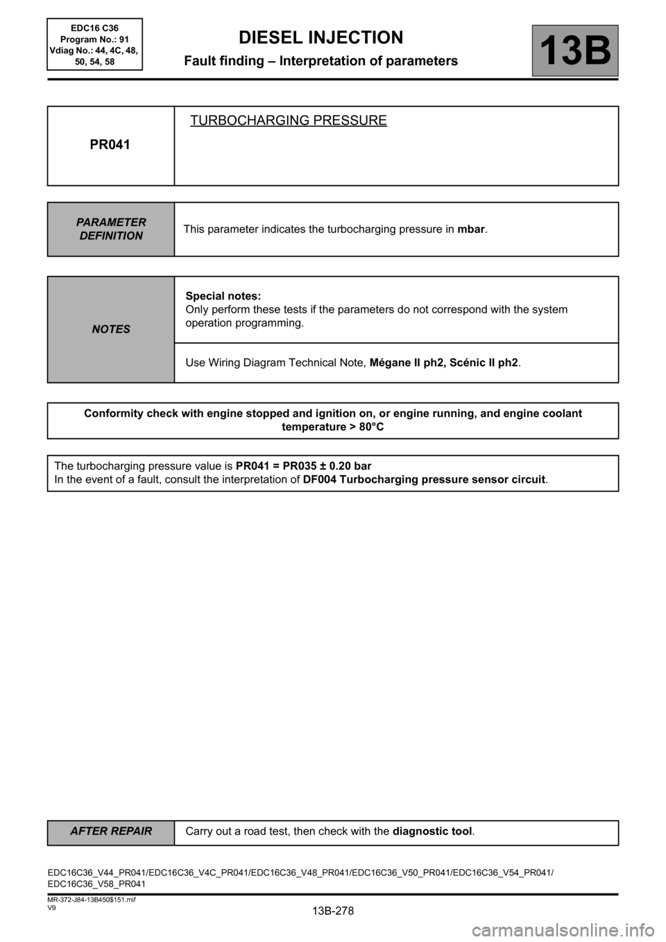
PR041TURBOCHARGING PRESSURE
PARAMETER
DEFINITIONThis parameter indicates the turbocharging pressure in mbar.
NOTESSpecial notes:
Only perform these tests if the parameters do not correspond with the system
operation programming.
Use Wiring Diagram Technical Note, Mégane II ph2, Scénic II ph2.
Conformity check with engine stopped and ignition on, or engine running, and engine coolant
temperature > 80°C
The turbocharging pressure value is PR041 = PR035 ± 0.20 bar
In the event of a fault, consult the interpretation of DF004 Turbocharging pressure sensor circuit.
EDC16C36_V44_PR041/EDC16C36_V4C_PR041/EDC16C36_V48_PR041/EDC16C36_V50_PR041/EDC16C36_V54_PR041/
EDC16C36_V58_PR041EDC16 C36
Program No.: 91
Vdiag No.: 44, 4C, 48,
50, 54, 58
Page 279 of 431

13B-279
AFTER REPAIRCarry out a road test, then check with the diagnostic tool.
V9 MR-372-J84-13B450$151.mif
DIESEL INJECTION
Fault finding – Interpretation of parameters13B
PR041
CONTINUED
Sensor electrical conformity
Check the continuity and absence of interference resistance on the following connections:
– connection code 3LQ,
– connection code 3LP,
– connection code 3LN.
between components 120 and 1071.
If any of the connections are faulty and there is a repair method (see Technical Note 6015A, Electrical wiring
repair, Wiring: precautions for repairs), repair the wiring; otherwise replace the wiring.
Vehicle with ignition on, and the engine stopped for over 1 minute:
Compare the values of PR041 and PR035 Atmospheric pressure.
If the difference between PR041 and PR035 Atmospheric pressure is greater than 0.1 bar,
check the value of PR035 "Atmospheric pressure" by comparing it with the reading on a vehicle in the workshop
which is correct.
If the value of PR035 Atmospheric pressure is not correct (difference greater than 0.1 bar between the 2
vehicles), contact the Techline.
Otherwise (when the value PR035 Atmospheric pressure is correct), change the turbocharging pressure sensor.
If the difference between PR041 and PR035 Atmospheric pressure is greater than 0.1 bar.
Start the engine, with the engine idling:
Compare the values of PR041 and PR035 Atmospheric pressure.
If the difference between PR041 and PR035 Atmospheric pressure is greater than 0.2 bar.
Check the air inlet circuit:
The low and high pressure air circuit is sealed and not obstructed: the pipes and mounting clamps are present
and tightened, turbocharging pressure sensor, intercooler, etc. are fitted.
Check that the damper valve is not jammed closed.
Repair if necessary.
EDC16 C36
Program No.: 91
Vdiag No.: 44, 4C, 48,
50, 54, 58
Page 282 of 431
13B-282
AFTER REPAIRCarry out a road test, then check with the diagnostic tool.
V9 MR-372-J84-13B450$151.mif
DIESEL INJECTION
Fault finding – Interpretation of parameters13B
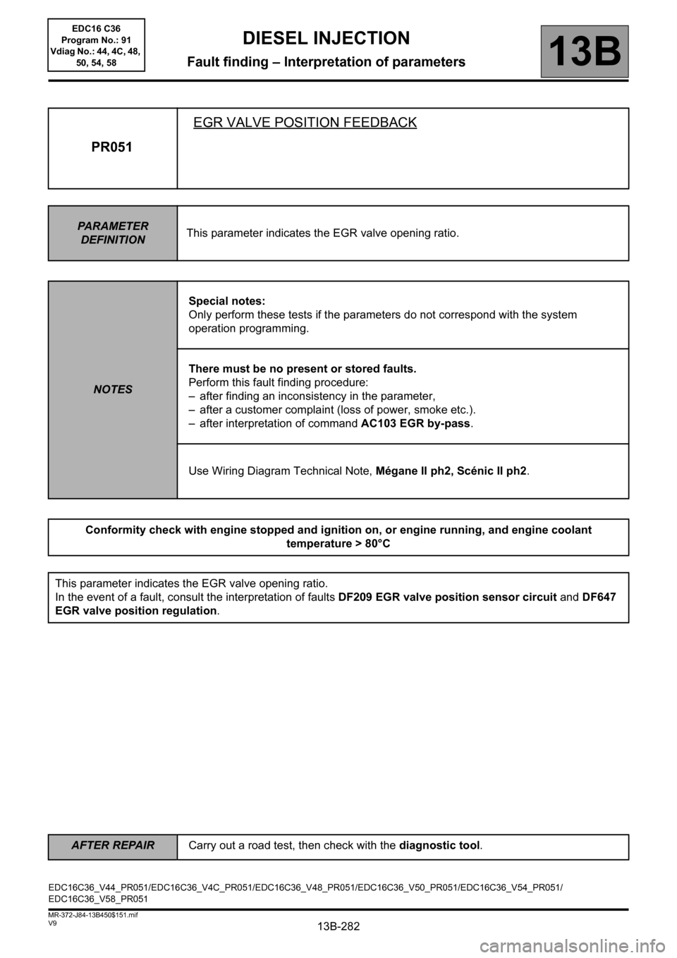
PR051EGR VALVE POSITION FEEDBACK
PARAMETER
DEFINITIONThis parameter indicates the EGR valve opening ratio.
NOTESSpecial notes:
Only perform these tests if the parameters do not correspond with the system
operation programming.
There must be no present or stored faults.
Perform this fault finding procedure:
– after finding an inconsistency in the parameter,
– after a customer complaint (loss of power, smoke etc.).
– after interpretation of command AC103 EGR by-pass.
Use Wiring Diagram Technical Note, Mégane II ph2, Scénic II ph2.
Conformity check with engine stopped and ignition on, or engine running, and engine coolant
temperature > 80°C
This parameter indicates the EGR valve opening ratio.
In the event of a fault, consult the interpretation of faults DF209 EGR valve position sensor circuit and DF647
EGR valve position regulation.
EDC16C36_V44_PR051/EDC16C36_V4C_PR051/EDC16C36_V48_PR051/EDC16C36_V50_PR051/EDC16C36_V54_PR051/
EDC16C36_V58_PR051EDC16 C36
Program No.: 91
Vdiag No.: 44, 4C, 48,
50, 54, 58
Page 283 of 431

13B-283
AFTER REPAIRCarry out a road test, then check with the diagnostic tool.
V9 MR-372-J84-13B450$151.mif
DIESEL INJECTION
Fault finding – Interpretation of parameters13B
PR051
CONTINUED
Sensor electrical conformity
Check the continuity and absence of interference resistance of the following connections:
– connection code3JM,
– connection code3EL,
– connection code3GC,
between components 120 and 1460 or 169.
If the connection or connections are faulty and there is a repair procedure (see Technical Note 6015A, Repairing
electrical wiring, Wiring: Precautions for repair), repair the wiring, otherwise replace it.
If the fault is still present, contact the Techline
EDC16 C36
Program No.: 91
Vdiag No.: 44, 4C, 48,
50, 54, 58