wiring RENAULT SCENIC 2011 J95 / 3.G Engine And Peripherals EDC16C36 Workshop Manual
[x] Cancel search | Manufacturer: RENAULT, Model Year: 2011, Model line: SCENIC, Model: RENAULT SCENIC 2011 J95 / 3.GPages: 431, PDF Size: 2.03 MB
Page 286 of 431
13B-286
AFTER REPAIRCarry out a road test, then check with the diagnostic tool.
V9 MR-372-J84-13B450$151.mif
DIESEL INJECTION
Fault finding – Interpretation of parameters13B
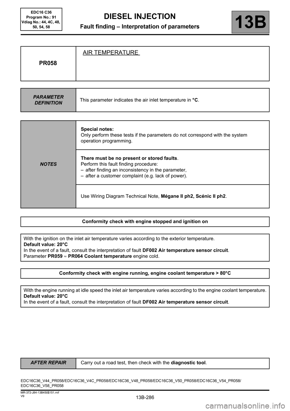
PR058AIR TEMPERATURE
PARAMETER
DEFINITIONThis parameter indicates the air inlet temperature in °C.
NOTESSpecial notes:
Only perform these tests if the parameters do not correspond with the system
operation programming.
There must be no present or stored faults.
Perform this fault finding procedure:
– after finding an inconsistency in the parameter,
– after a customer complaint (e.g. lack of power).
Use Wiring Diagram Technical Note, Mégane II ph2, Scénic II ph2.
Conformity check with engine stopped and ignition on
With the ignition on the inlet air temperature varies according to the exterior temperature.
Default value: 20°C
In the event of a fault, consult the interpretation of fault DF002 Air temperature sensor circuit.
Parameter PR059 ≈ PR064 Coolant temperature engine cold.
Conformity check with engine running, engine coolant temperature > 80°C
With the engine running at idle speed the inlet air temperature varies according to the engine coolant temperature.
Default value: 20°C
In the event of a fault, consult the interpretation of fault DF002 Air temperature sensor circuit.
EDC16C36_V44_PR058/EDC16C36_V4C_PR058/EDC16C36_V48_PR058/EDC16C36_V50_PR058/EDC16C36_V54_PR058/
EDC16C36_V58_PR058EDC16 C36
Program No.: 91
Vdiag No.: 44, 4C, 48,
50, 54, 58
Page 287 of 431

13B-287
AFTER REPAIRCarry out a road test, then check with the diagnostic tool.
V9 MR-372-J84-13B450$151.mif
DIESEL INJECTION
Fault finding – Interpretation of parameters13B
PR058
CONTINUED
Sensor electrical conformity
With the flow sensor disconnected, check the insulation from earth of the following connection:
– Connection code 3ABQ between components 120 and 799.
Check the supply of + 12 V after the relay to the air flowmeter.
– Connection code 3FB of component 799.
If any of the connections are faulty and there is a repair method (see Technical Note 6015A, Electrical wiring
repair, Wiring: precautions for repairs), repair the wiring; otherwise replace the wiring.
Measure the resistance between connections 3ABQ and 3DW of component 799.
Replace the air flowmeter if the resistance is not approximately:
9202 Ω ± 487 Ω at -10°C
5774 Ω ± 277 Ω at 0°C
3714 Ω ± 161 Ω at +10°C
2448 Ω ± 96 Ω at +20°C
1671 Ω ± 59 Ω at +30°C
1150 Ω ± 36 Ω at +40°C
817 Ω ± 23 Ω at +50°C
583 Ω ± 15 Ω at +60°C
427 Ω ± 9 Ω at +70°C
316 Ω ± 6 Ω at +80°C
238 Ω ± 4 Ω at +90°C
EDC16 C36
Program No.: 91
Vdiag No.: 44, 4C, 48,
50, 54, 58
Page 288 of 431
13B-288
AFTER REPAIRCarry out a road test, then check with the diagnostic tool.
V9 MR-372-J84-13B450$151.mif
DIESEL INJECTION
Fault finding – Interpretation of parameters13B
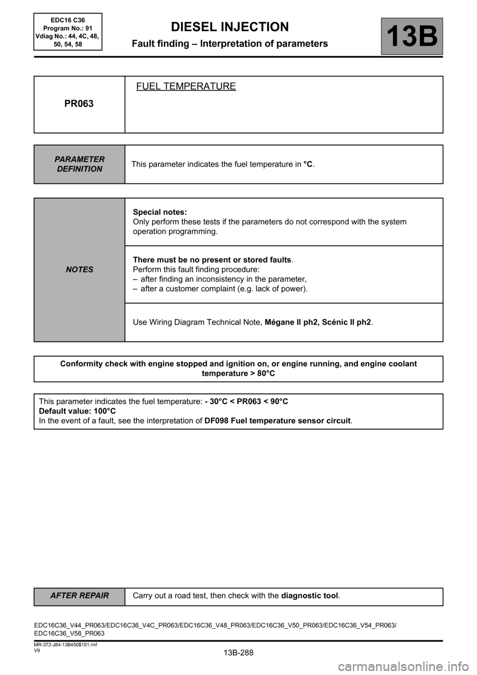
PR063FUEL TEMPERATURE
PARAMETER
DEFINITIONThis parameter indicates the fuel temperature in °C.
NOTESSpecial notes:
Only perform these tests if the parameters do not correspond with the system
operation programming.
There must be no present or stored faults.
Perform this fault finding procedure:
– after finding an inconsistency in the parameter,
– after a customer complaint (e.g. lack of power).
Use Wiring Diagram Technical Note, Mégane II ph2, Scénic II ph2.
Conformity check with engine stopped and ignition on, or engine running, and engine coolant
temperature > 80°C
This parameter indicates the fuel temperature: - 30°C < PR063 < 90°C
Default value: 100°C
In the event of a fault, see the interpretation of DF098 Fuel temperature sensor circuit.
EDC16C36_V44_PR063/EDC16C36_V4C_PR063/EDC16C36_V48_PR063/EDC16C36_V50_PR063/EDC16C36_V54_PR063/
EDC16C36_V58_PR063EDC16 C36
Program No.: 91
Vdiag No.: 44, 4C, 48,
50, 54, 58
Page 289 of 431

13B-289
AFTER REPAIRCarry out a road test, then check with the diagnostic tool.
V9 MR-372-J84-13B450$151.mif
DIESEL INJECTION
Fault finding – Interpretation of parameters13B
PR063
CONTINUED
Sensor electrical conformity
Check the continuity and absence of interference resistance on the following connections:
– Connection code 3FAB,
– Connection code 3LD,
between components 120 and 1066.
If any of the connections are faulty and there is a repair method (see Technical Note 6015A, Electrical wiring
repair, Wiring: precautions for repairs), repair the wiring; otherwise replace the wiring.
Measure the resistance between connections 3FAB and 3LD of component 1066
Replace the sensor if the resistance is not approximately:
3820 Ω ± 282 at + 10°C
2050 Ω ± 100 at + 25°C
810 Ω
± 47 at + 50°C
EDC16 C36
Program No.: 91
Vdiag No.: 44, 4C, 48,
50, 54, 58
Page 290 of 431
13B-290
AFTER REPAIRCarry out a road test, then check with the diagnostic tool.
V9 MR-372-J84-13B450$151.mif
DIESEL INJECTION
Fault finding – Interpretation of parameters13B
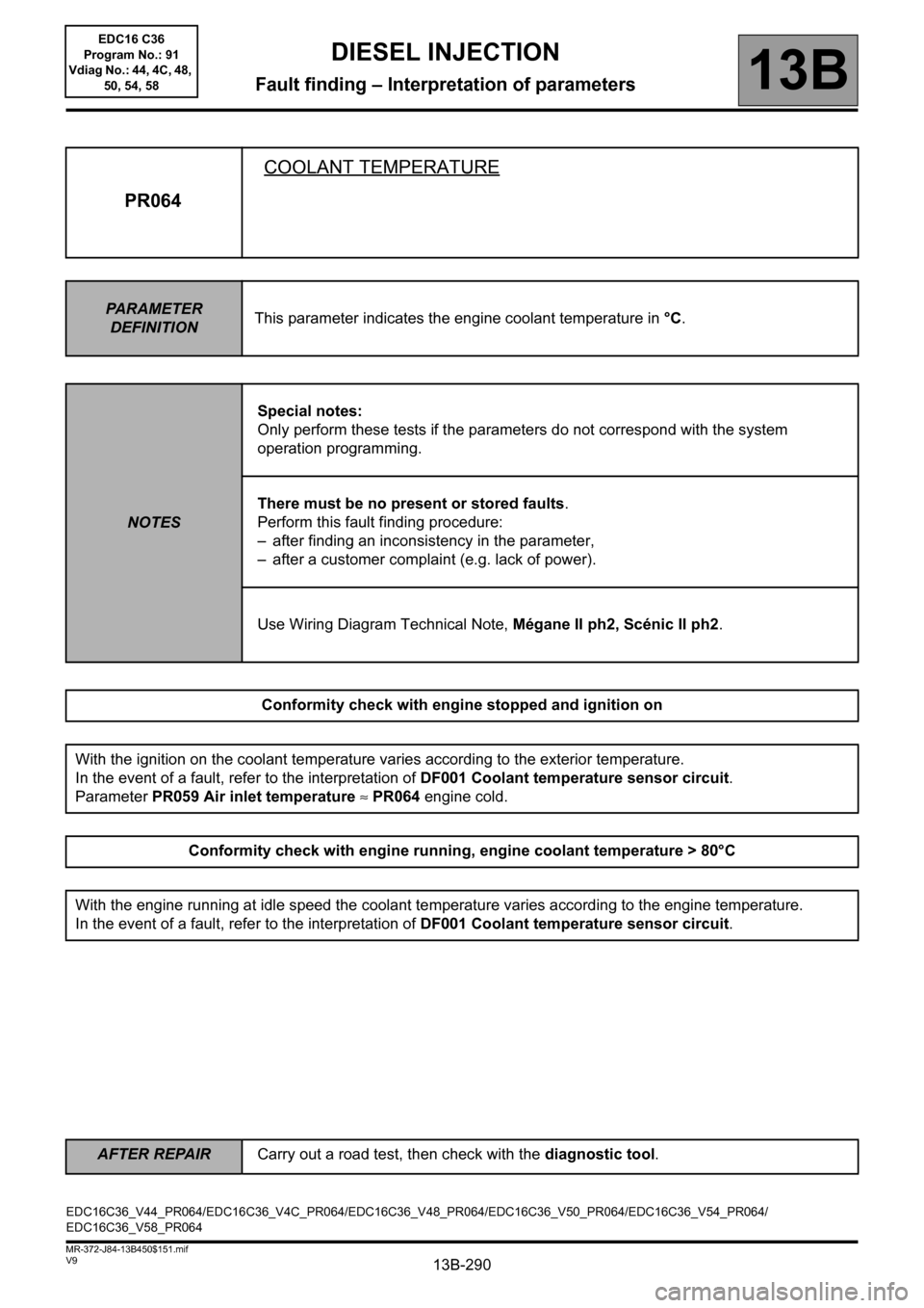
PR064COOLANT TEMPERATURE
PARAMETER
DEFINITIONThis parameter indicates the engine coolant temperature in °C.
NOTESSpecial notes:
Only perform these tests if the parameters do not correspond with the system
operation programming.
There must be no present or stored faults.
Perform this fault finding procedure:
– after finding an inconsistency in the parameter,
– after a customer complaint (e.g. lack of power).
Use Wiring Diagram Technical Note, Mégane II ph2, Scénic II ph2.
Conformity check with engine stopped and ignition on
With the ignition on the coolant temperature varies according to the exterior temperature.
In the event of a fault, refer to the interpretation of DF001 Coolant temperature sensor circuit.
Parameter PR059 Air inlet temperature ≈ PR064 engine cold.
Conformity check with engine running, engine coolant temperature > 80°C
With the engine running at idle speed the coolant temperature varies according to the engine temperature.
In the event of a fault, refer to the interpretation of DF001 Coolant temperature sensor circuit.
EDC16C36_V44_PR064/EDC16C36_V4C_PR064/EDC16C36_V48_PR064/EDC16C36_V50_PR064/EDC16C36_V54_PR064/
EDC16C36_V58_PR064EDC16 C36
Program No.: 91
Vdiag No.: 44, 4C, 48,
50, 54, 58
Page 291 of 431

13B-291
AFTER REPAIRCarry out a road test, then check with the diagnostic tool.
V9 MR-372-J84-13B450$151.mif
DIESEL INJECTION
Fault finding – Interpretation of parameters13B
PR064
CONTINUED
Sensor electrical conformity
Check the continuity and absence of interference resistance on the following connections:
– connection code3C,
– connection code 3JK,
between components 120 and 244.
If any of the connections are faulty and there is a repair method (see Technical Note 6015A, Electrical wiring
repair, Wiring: precautions for repairs), repair the wiring; otherwise replace the wiring.
Measure the resistance between connections 3C and 3JK of component 244.
Replace the sensor if the resistance is not:
12460 Ω ± 1128 Ω at - 10°C
2252 Ω ± 112 Ω at +25°C
811 Ω ± 39 Ω
at +50°C
283 Ω ± 8 Ω at +80°C
115 Ω ± 3 Ω at +110°C
EDC16 C36
Program No.: 91
Vdiag No.: 44, 4C, 48,
50, 54, 58
Page 308 of 431
13B-308V9 MR-372-J84-13B450$152.mif
DIESEL INJECTION
Fault finding – Interpretation of parameters13B
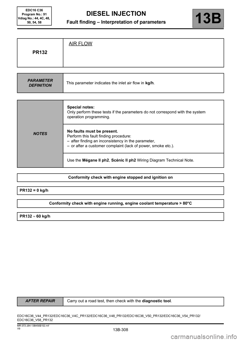
PR132AIR FLOW
PARAMETER
DEFINITIONThis parameter indicates the inlet air flow in kg/h.
NOTESSpecial notes:
Only perform these tests if the parameters do not correspond with the system
operation programming.
No faults must be present.
Perform this fault finding procedure:
– after finding an inconsistency in the parameter,
– or after a customer complaint (lack of power, smoke etc.).
Use the Mégane II ph2, Scénic II ph2 Wiring Diagram Technical Note.
Conformity check with engine stopped and ignition on
PR132 = 0 kg/h
Conformity check with engine running, engine coolant temperature > 80°C
PR132 ≈ 60 kg/h
EDC16C36_V44_PR132/EDC16C36_V4C_PR132/EDC16C36_V48_PR132/EDC16C36_V50_PR132/EDC16C36_V54_PR132/
EDC16C36_V58_PR132
AFTER REPAIRCarry out a road test, then check with the diagnostic tool.
EDC16 C36
Program No.: 91
Vdiag No.: 44, 4C, 48,
50, 54, 58
Page 367 of 431
13B-367
AFTER REPAIRRepeat the conformity check in the interpretation of statuses and parameters
V9 MR-372-J84-13B450$170.mif
DIESEL INJECTION
Fault finding – Interpretation of commands13B
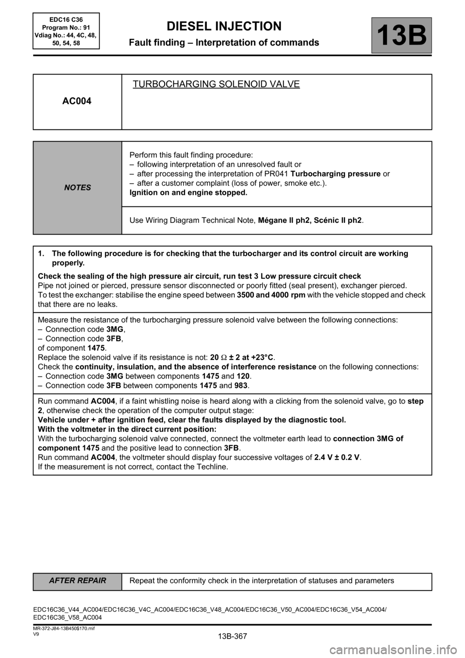
AC004TURBOCHARGING SOLENOID VALVE
NOTESPerform this fault finding procedure:
– following interpretation of an unresolved fault or
– after processing the interpretation of PR041 Turbocharging pressure or
– after a customer complaint (loss of power, smoke etc.).
Ignition on and engine stopped.
Use Wiring Diagram Technical Note, Mégane II ph2, Scénic II ph2.
1. The following procedure is for checking that the turbocharger and its control circuit are working
properly.
Check the sealing of the high pressure air circuit, run test 3 Low pressure circuit check
Pipe not joined or pierced, pressure sensor disconnected or poorly fitted (seal present), exchanger pierced.
To test the exchanger: stabilise the engine speed between 3500 and 4000 rpm with the vehicle stopped and check
that there are no leaks.
Measure the resistance of the turbocharging pressure solenoid valve between the following connections:
– Connection code 3MG,
– Connection code 3FB,
of component 1475.
Replace the solenoid valve if its resistance is not: 20 Ω ± 2 at +23°C.
Check the continuity, insulation, and the absence of interference resistance on the following connections:
– Connection code 3MG between components 1475 and 120.
– Connection code 3FB between components 1475 and 983.
Run command AC004, if a faint whistling noise is heard along with a clicking from the solenoid valve, go to step
2, otherwise check the operation of the computer output stage:
Vehicle under + after ignition feed, clear the faults displayed by the diagnostic tool.
With the voltmeter in the direct current position:
With the turbocharging solenoid valve connected, connect the voltmeter earth lead to connection 3MG of
component 1475 and the positive lead to connection3FB.
Run command AC004, the voltmeter should display four successive voltages of 2.4 V ± 0.2 V.
If the measurement is not correct, contact the Techline.
EDC16C36_V44_AC004/EDC16C36_V4C_AC004/EDC16C36_V48_AC004/EDC16C36_V50_AC004/EDC16C36_V54_AC004/
EDC16C36_V58_AC004EDC16 C36
Program No.: 91
Vdiag No.: 44, 4C, 48,
50, 54, 58
Page 369 of 431
13B-369
AFTER REPAIRRepeat the conformity check in the interpretation of statuses and parameters
V9 MR-372-J84-13B450$170.mif
DIESEL INJECTION
Fault finding – Interpretation of commands13B
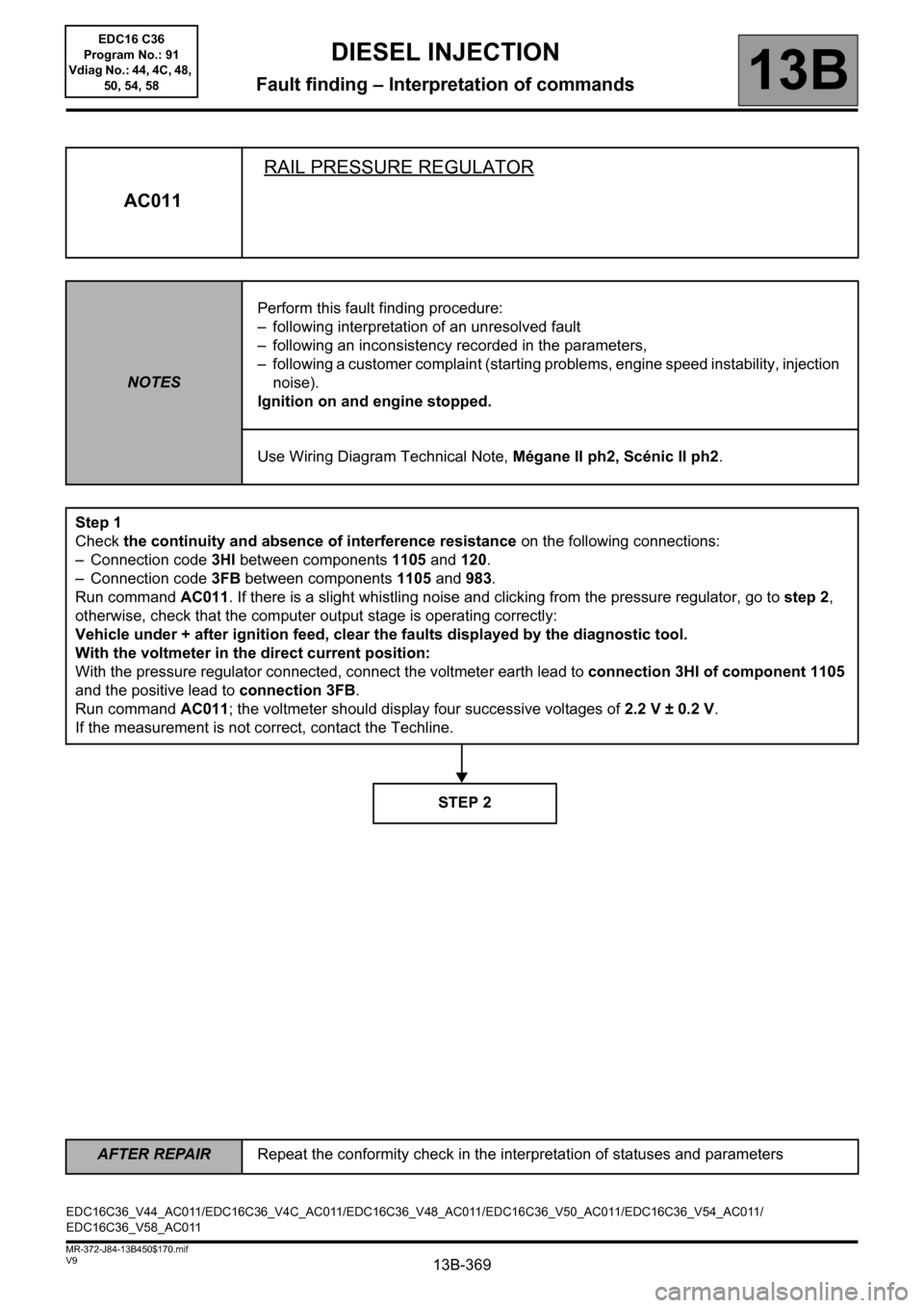
AC011RAIL PRESSURE REGULATOR
NOTESPerform this fault finding procedure:
– following interpretation of an unresolved fault
– following an inconsistency recorded in the parameters,
– following a customer complaint (starting problems, engine speed instability, injection
noise).
Ignition on and engine stopped.
Use Wiring Diagram Technical Note, Mégane II ph2, Scénic II ph2.
Step 1
Check the continuity and absence of interference resistance on the following connections:
– Connection code 3HI between components 1105 and 120.
– Connection code 3FB between components 1105 and 983.
Run command AC011. If there is a slight whistling noise and clicking from the pressure regulator, go to step 2,
otherwise, check that the computer output stage is operating correctly:
Vehicle under + after ignition feed, clear the faults displayed by the diagnostic tool.
With the voltmeter in the direct current position:
With the pressure regulator connected, connect the voltmeter earth lead to connection 3HI of component 1105
and the positive lead to connection 3FB.
Run command AC011; the voltmeter should display four successive voltages of 2.2 V ± 0.2 V.
If the measurement is not correct, contact the Techline.
STEP 2
EDC16C36_V44_AC011/EDC16C36_V4C_AC011/EDC16C36_V48_AC011/EDC16C36_V50_AC011/EDC16C36_V54_AC011/
EDC16C36_V58_AC011EDC16 C36
Program No.: 91
Vdiag No.: 44, 4C, 48,
50, 54, 58
Page 371 of 431

13B-371
AFTER REPAIRRepeat the conformity check in the interpretation of statuses and parameters
V9 MR-372-J84-13B450$170.mif
DIESEL INJECTION
Fault finding – Interpretation of commands13B
AC012DAMPER VALVE
NOTESCarry out this interpretation:
– after DF226 Damper valve
– or after a customer complaint (starting faults, poor performance).
Ignition on and engine stopped.
Use Wiring Diagram Technical Note, Mégane II ph2, Scénic II ph2.
Check the continuity, insulation and absence of interference resistance on the following connections:
– Connection code 3VN,
– Connection code 3VM,
between components 1461 and 120.
Check for +12 V on connection 3FB of component 1461.
Check for earth on connectionNT of component1461.
If there is a repair method (see Technical Note 6015A, Repairing electrical wiring, Wiring: Precautions for
repair), repair the wiring, otherwise replace it.
With the vehicle ignition on, and the engine stopped:
Check that the damper valve is open.
If not, clean or replace the damper valve.
Actuate the valve using command AC012 and check the damper valve travel and the rest position of the valve.
Check the operation of the computer output stage with a voltmeter:
Actuate the valve with command AC012.
Positive lead to connection3FB and negative lead to connection3VN of component1461.
The voltmeter should display three cycles of ON-OFF (12.5 V then return to 0V).
If the measurement is correct, replace the damper valve.
If the measurement does not show any operation, contact the Techline.
EDC16C36_V44_AC012/EDC16C36_V4C_AC012/EDC16C36_V48_AC012/EDC16C36_V50_AC012/EDC16C36_V54_AC012/
EDC16C36_V58_AC012EDC16 C36
Program No.: 91
Vdiag No.: 44, 4C, 48,
50, 54, 58