charging RENAULT SCENIC 2011 J95 / 3.G Engine And Peripherals EDC16C36 Owner's Manual
[x] Cancel search | Manufacturer: RENAULT, Model Year: 2011, Model line: SCENIC, Model: RENAULT SCENIC 2011 J95 / 3.GPages: 431, PDF Size: 2.03 MB
Page 94 of 431
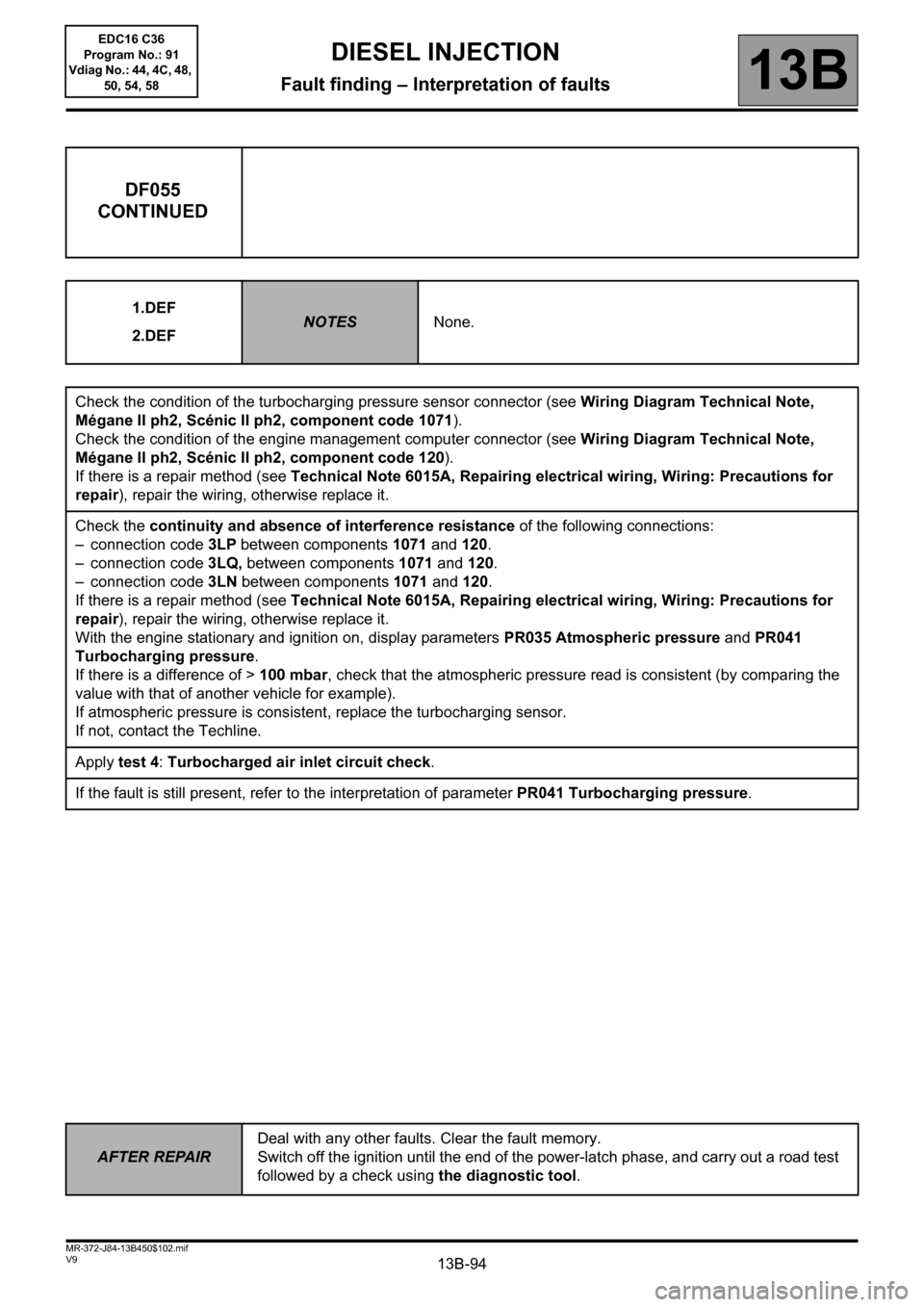
13B-94V9 MR-372-J84-13B450$102.mif
DIESEL INJECTION
Fault finding – Interpretation of faults13B
DF055
CONTINUED
1.DEF
2.DEFNOTESNone.
Check the condition of the turbocharging pressure sensor connector (see Wiring Diagram Technical Note,
Mégane II ph2, Scénic II ph2, component code 1071).
Check the condition of the engine management computer connector (see Wiring Diagram Technical Note,
Mégane II ph2, Scénic II ph2, component code 120).
If there is a repair method (see Technical Note 6015A, Repairing electrical wiring, Wiring: Precautions for
repair), repair the wiring, otherwise replace it.
Check the continuity and absence of interference resistance of the following connections:
– connection code 3LP between components 1071 and 120.
– connection code 3LQ, between components 1071 and 120.
– connection code 3LN between components 1071 and 120.
If there is a repair method (see Technical Note 6015A, Repairing electrical wiring, Wiring: Precautions for
repair), repair the wiring, otherwise replace it.
With the engine stationary and ignition on, display parameters PR035 Atmospheric pressure and PR041
Turbocharging pressure.
If there is a difference of > 100 mbar, check that the atmospheric pressure read is consistent (by comparing the
value with that of another vehicle for example).
If atmospheric pressure is consistent, replace the turbocharging sensor.
If not, contact the Techline.
Apply test 4: Turbocharged air inlet circuit check.
If the fault is still present, refer to the interpretation of parameter PR041 Turbocharging pressure.
AFTER REPAIRDeal with any other faults. Clear the fault memory.
Switch off the ignition until the end of the power-latch phase, and carry out a road test
followed by a check using the diagnostic tool.
EDC16 C36
Program No.: 91
Vdiag No.: 44, 4C, 48,
50, 54, 58
Page 125 of 431
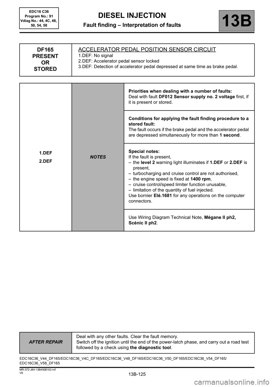
13B-125
AFTER REPAIRDeal with any other faults. Clear the fault memory.
Switch off the ignition until the end of the power-latch phase, and carry out a road test
followed by a check using the diagnostic tool.
V9 MR-372-J84-13B450$103.mif
DIESEL INJECTION
Fault finding – Interpretation of faults13B
DF165
PRESENT
OR
STOREDACCELERATOR PEDAL POSITION SENSOR CIRCUIT
1.DEF: No signal
2.DEF: Accelerator pedal sensor locked
3.DEF: Detection of accelerator pedal depressed at same time as brake pedal.
1.DEF
2.DEF
NOTESPriorities when dealing with a number of faults:
Deal with fault DF012 Sensor supply no. 2 voltage first, if
it is present or stored.
Conditions for applying the fault finding procedure to a
stored fault:
The fault occurs if the brake pedal and the accelerator pedal
are depressed simultaneously for more than 1 second.
Special notes:
If the fault is present,
–the level 2 warning light illuminates if 1.DEF or 2.DEF is
present,
– turbocharging and cruise control are not authorised,
– the engine speed is fixed at 1400 rpm,
– cruise control/speed limiter function unusable,
– limitation of the quantity of fuel injected.
Use bornier Elé.1681 for any operations on the computer
connectors.
Use Wiring Diagram Technical Note, Mégane II ph2,
Scénic II ph2.
EDC16C36_V44_DF165/EDC16C36_V4C_DF165/EDC16C36_V48_DF165/EDC16C36_V50_DF165/EDC16C36_V54_DF165/
EDC16C36_V58_DF165EDC16 C36
Program No.: 91
Vdiag No.: 44, 4C, 48,
50, 54, 58
Page 168 of 431
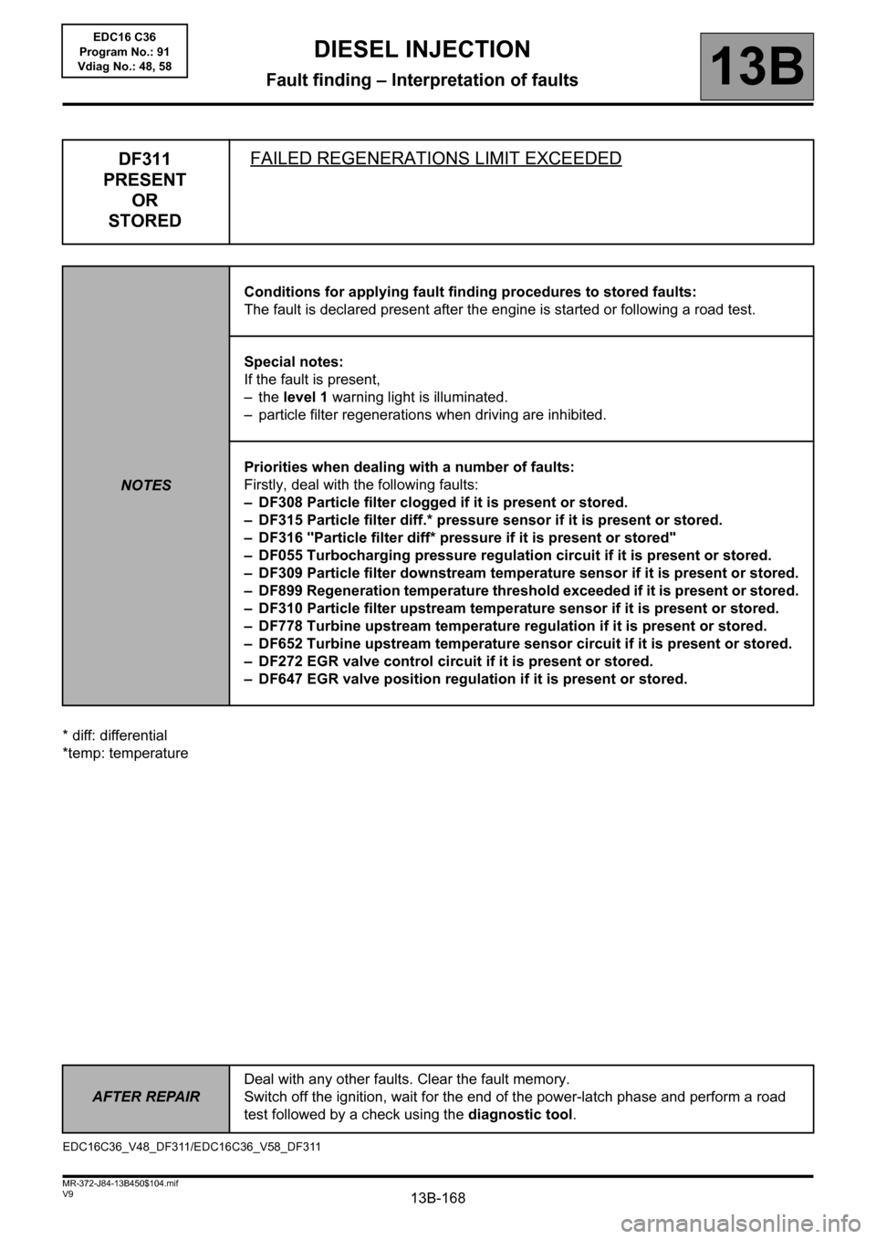
13B-168
AFTER REPAIRDeal with any other faults. Clear the fault memory.
Switch off the ignition, wait for the end of the power-latch phase and perform a road
test followed by a check using the diagnostic tool.
V9 MR-372-J84-13B450$104.mif
13B
* diff: differential
*temp: temperature
DF311
PRESENT
OR
STOREDFAILED REGENERATIONS LIMIT EXCEEDED
NOTESConditions for applying fault finding procedures to stored faults:
The fault is declared present after the engine is started or following a road test.
Special notes:
If the fault is present,
–the level 1 warning light is illuminated.
– particle filter regenerations when driving are inhibited.
Priorities when dealing with a number of faults:
Firstly, deal with the following faults:
– DF308 Particle filter clogged if it is present or stored.
– DF315 Particle filter diff.* pressure sensor if it is present or stored.
– DF316 "Particle filter diff* pressure if it is present or stored"
– DF055 Turbocharging pressure regulation circuit if it is present or stored.
– DF309 Particle filter downstream temperature sensor if it is present or stored.
– DF899 Regeneration temperature threshold exceeded if it is present or stored.
– DF310 Particle filter upstream temperature sensor if it is present or stored.
– DF778 Turbine upstream temperature regulation if it is present or stored.
– DF652 Turbine upstream temperature sensor circuit if it is present or stored.
– DF272 EGR valve control circuit if it is present or stored.
– DF647 EGR valve position regulation if it is present or stored.
EDC16C36_V48_DF311/EDC16C36_V58_DF311
DIESEL INJECTION
Fault finding – Interpretation of faults
EDC16 C36
Program No.: 91
Vdiag No.: 48, 58
Page 183 of 431
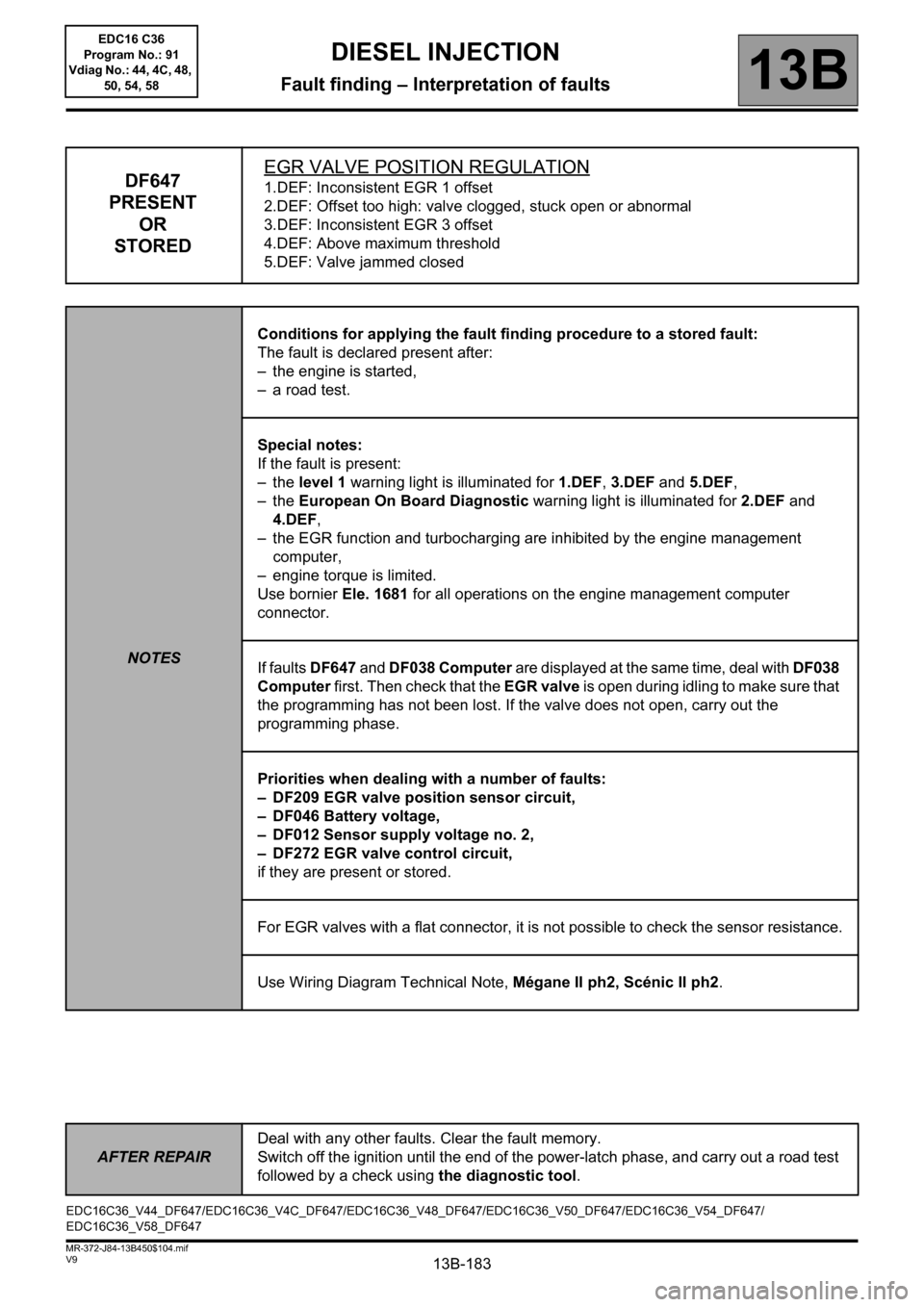
13B-183
AFTER REPAIRDeal with any other faults. Clear the fault memory.
Switch off the ignition until the end of the power-latch phase, and carry out a road test
followed by a check using the diagnostic tool.
V9 MR-372-J84-13B450$104.mif
DIESEL INJECTION
Fault finding – Interpretation of faults13B
DF647
PRESENT
OR
STOREDEGR VALVE POSITION REGULATION1.DEF: Inconsistent EGR 1 offset
2.DEF: Offset too high: valve clogged, stuck open or abnormal
3.DEF: Inconsistent EGR 3 offset
4.DEF: Above maximum threshold
5.DEF: Valve jammed closed
NOTESConditions for applying the fault finding procedure to a stored fault:
The fault is declared present after:
– the engine is started,
– a road test.
Special notes:
If the fault is present:
–the level 1 warning light is illuminated for 1.DEF, 3.DEF and 5.DEF,
–the European On Board Diagnostic warning light is illuminated for 2.DEF and
4.DEF,
– the EGR function and turbocharging are inhibited by the engine management
computer,
– engine torque is limited.
Use bornier Ele. 1681 for all operations on the engine management computer
connector.
If faults DF647 and DF038 Computer are displayed at the same time, deal with DF038
Computer first. Then check that the EGR valve is open during idling to make sure that
the programming has not been lost. If the valve does not open, carry out the
programming phase.
Priorities when dealing with a number of faults:
– DF209 EGR valve position sensor circuit,
– DF046 Battery voltage,
– DF012 Sensor supply voltage no. 2,
– DF272 EGR valve control circuit,
if they are present or stored.
For EGR valves with a flat connector, it is not possible to check the sensor resistance.
Use Wiring Diagram Technical Note, Mégane II ph2, Scénic II ph2.
EDC16C36_V44_DF647/EDC16C36_V4C_DF647/EDC16C36_V48_DF647/EDC16C36_V50_DF647/EDC16C36_V54_DF647/
EDC16C36_V58_DF647EDC16 C36
Program No.: 91
Vdiag No.: 44, 4C, 48,
50, 54, 58
Page 229 of 431
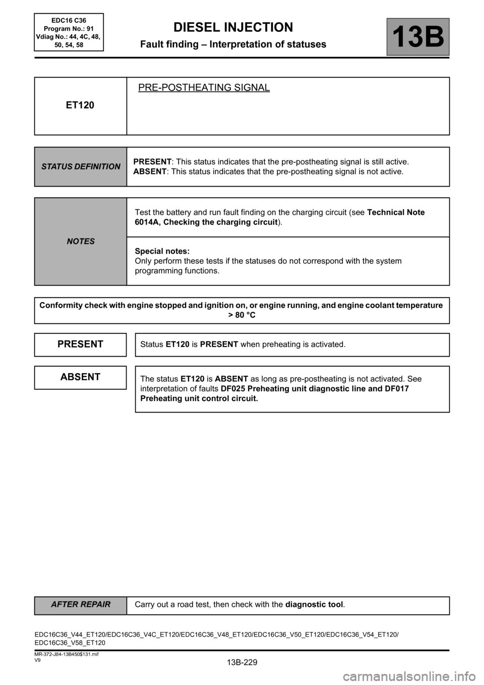
13B-229V9 MR-372-J84-13B450$131.mif
DIESEL INJECTION
Fault finding – Interpretation of statuses13B
ET120PRE-POSTHEATING SIGNAL
STATUS DEFINITIONPRESENT: This status indicates that the pre-postheating signal is still active.
ABSENT: This status indicates that the pre-postheating signal is not active.
NOTESTest the battery and run fault finding on the charging circuit (see Technical Note
6014A, Checking the charging circuit).
Special notes:
Only perform these tests if the statuses do not correspond with the system
programming functions.
Conformity check with engine stopped and ignition on, or engine running, and engine coolant temperature
> 80 °C
PRESENTStatus ET120 is PRESENT when preheating is activated.
ABSENTThe status ET120 is ABSENT as long as pre-postheating is not activated. See
interpretation of faults DF025 Preheating unit diagnostic line and DF017
Preheating unit control circuit.
EDC16C36_V44_ET120/EDC16C36_V4C_ET120/EDC16C36_V48_ET120/EDC16C36_V50_ET120/EDC16C36_V54_ET120/
EDC16C36_V58_ET120
AFTER REPAIRCarry out a road test, then check with the diagnostic tool.
EDC16 C36
Program No.: 91
Vdiag No.: 44, 4C, 48,
50, 54, 58
Page 259 of 431

13B-259V9 MR-372-J84-13B450$140.mif
13B
EDC16 C36
Program No.: 91
Vdiag No.: 44, 4C, 48,
50, 54, 58
* OCR: Opening cycle ratioTool parameter Diagnostic tool title
PR002Alternator charge
PR005EGR valve opening setpoint
PR006Rail pressure regulator current
PR007Rail pressure regulator current setpoint
PR008Rail reference pressure
PR009Turbocharging pressure setpoint
PR015Engine torque
PR017Fuel flow
PR022EGR valve position feedback loop difference
PR025Mileage
PR030Accelerator pedal position
PR035Atmospheric pressure
PR037Refrigerant pressure
PR038Rail pressure
PR041Turbocharging pressure
PR045Power requested by heating elements
PR047Turbocharging pressure OCR*
PR048OCR* Rail pressure regulation valve
PR051EGR valve position feedback
PR053Engine speed requested by air conditioning
PR054Engine speed requested by heating elements
PR055Engine speed
PR058Air temperature
PR063Fuel temperature
PR064Coolant temperature
PR066Oil temperature
PR071Computer feed voltage
PR073Air flowmeter supply voltage
DIESEL INJECTION
Fault finding – Parameter summary table
Page 260 of 431

13B-260V9 MR-372-J84-13B450$140.mif
DIESEL INJECTION
Fault finding – Parameter summary table13B
EDC16 C36
Program No.: 91
Vdiag No.: 44, 4C, 48,
50, 54, 58
Tool parameter Diagnostic tool title
PR076Refrigerant sensor voltage
PR077EGR valve position sensor voltage
PR079Atmospheric pressure sensor voltage
PR080Rail pressure sensor voltage
PR082Fuel temperature sensor voltage
PR083Air temperature sensor voltage
PR084Coolant temperature sensor voltage.
PR086Pedal potentiometer voltage gang 1
PR088Pedal potentiometer gang 2 voltage
PR089Vehicle speed
PR128First EGR valve offset
PR129Last EGR valve offset
PR130Cruise control setpoint
PR131EGR air flow difference
PR132Air flow
PR146Inlet air flow
PR157Fuel flow setpoint
PR171Air flow setpoint for EGR
PR190Engine idle speed setpoint.
PR209Turbocharging pressure loop difference
PR213Rail pressure loop difference
PR224Turbocharging pressure sensor voltage
PR358Sensor reference voltage
PR364Cylinder no. 1 fuel flow correction
PR365Cylinder no. 4 fuel flow correction
PR381Particle filter downstream temperature
PR382Particle filter upstream temperature
PR383Weight of soot in the particle filter
Page 268 of 431
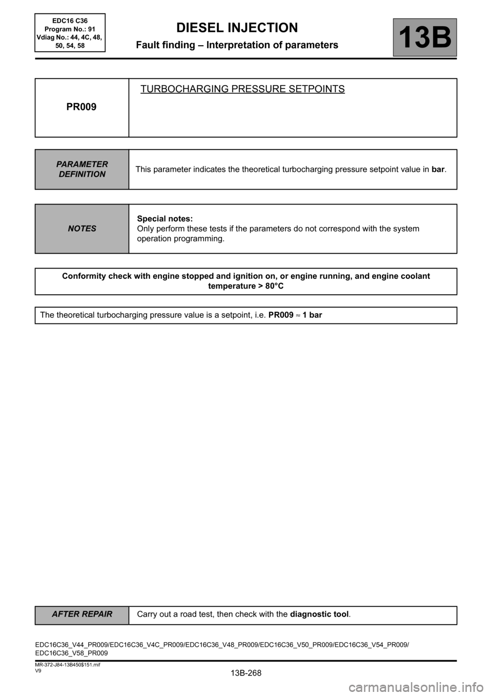
13B-268
AFTER REPAIRCarry out a road test, then check with the diagnostic tool.
V9 MR-372-J84-13B450$151.mif
DIESEL INJECTION
Fault finding – Interpretation of parameters13B
PR009TURBOCHARGING PRESSURE SETPOINTS
PARAMETER
DEFINITIONThis parameter indicates the theoretical turbocharging pressure setpoint value in bar.
NOTESSpecial notes:
Only perform these tests if the parameters do not correspond with the system
operation programming.
Conformity check with engine stopped and ignition on, or engine running, and engine coolant
temperature > 80°C
The theoretical turbocharging pressure value is a setpoint, i.e. PR009 ≈ 1 bar
EDC16C36_V44_PR009/EDC16C36_V4C_PR009/EDC16C36_V48_PR009/EDC16C36_V50_PR009/EDC16C36_V54_PR009/
EDC16C36_V58_PR009EDC16 C36
Program No.: 91
Vdiag No.: 44, 4C, 48,
50, 54, 58
Page 274 of 431
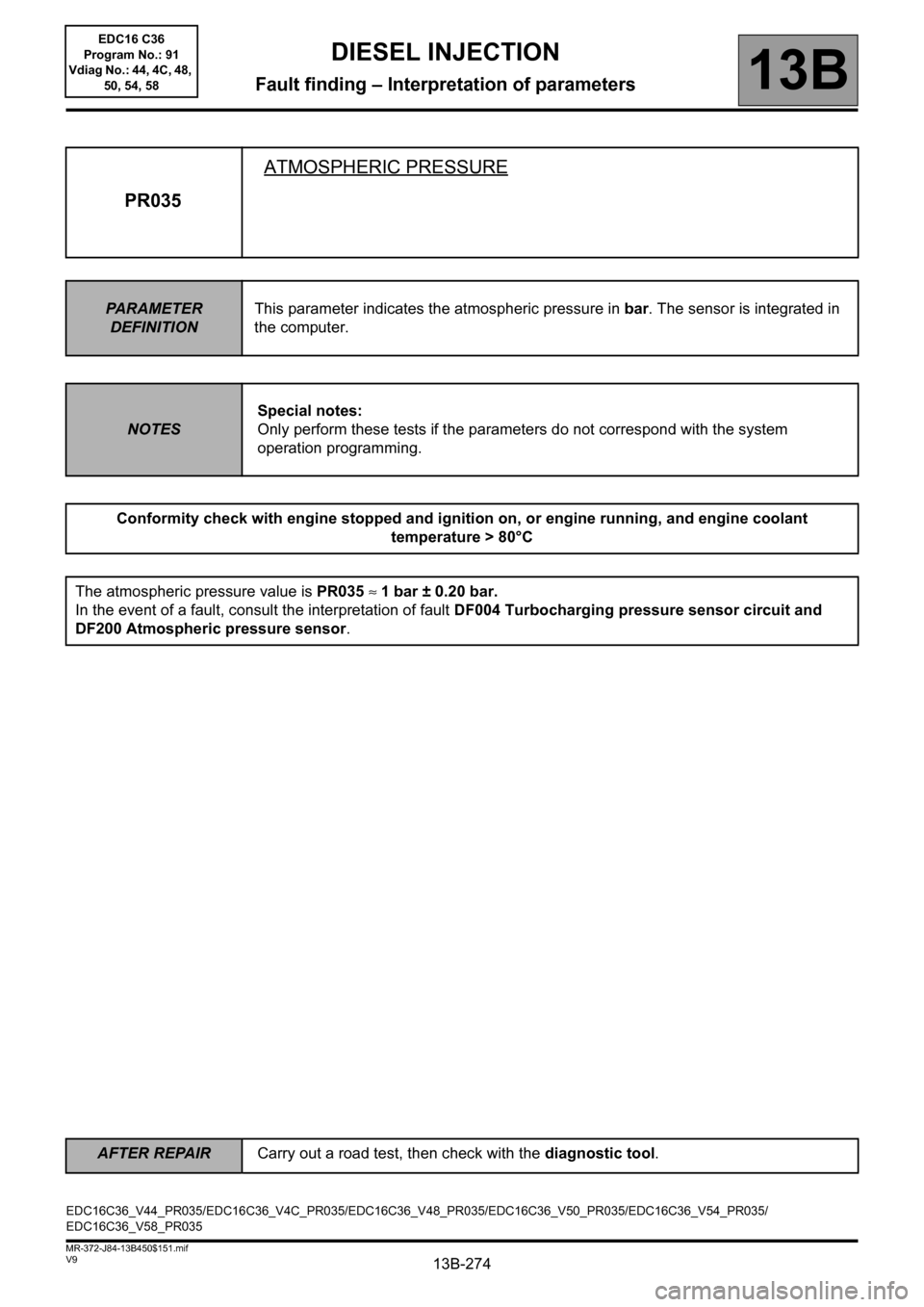
13B-274
AFTER REPAIRCarry out a road test, then check with the diagnostic tool.
V9 MR-372-J84-13B450$151.mif
DIESEL INJECTION
Fault finding – Interpretation of parameters13B
PR035ATMOSPHERIC PRESSURE
PARAMETER
DEFINITIONThis parameter indicates the atmospheric pressure in bar. The sensor is integrated in
the computer.
NOTESSpecial notes:
Only perform these tests if the parameters do not correspond with the system
operation programming.
Conformity check with engine stopped and ignition on, or engine running, and engine coolant
temperature > 80°C
The atmospheric pressure value is PR035 ≈ 1 bar ± 0.20 bar.
In the event of a fault, consult the interpretation of fault DF004 Turbocharging pressure sensor circuit and
DF200 Atmospheric pressure sensor.
EDC16C36_V44_PR035/EDC16C36_V4C_PR035/EDC16C36_V48_PR035/EDC16C36_V50_PR035/EDC16C36_V54_PR035/
EDC16C36_V58_PR035EDC16 C36
Program No.: 91
Vdiag No.: 44, 4C, 48,
50, 54, 58
Page 278 of 431
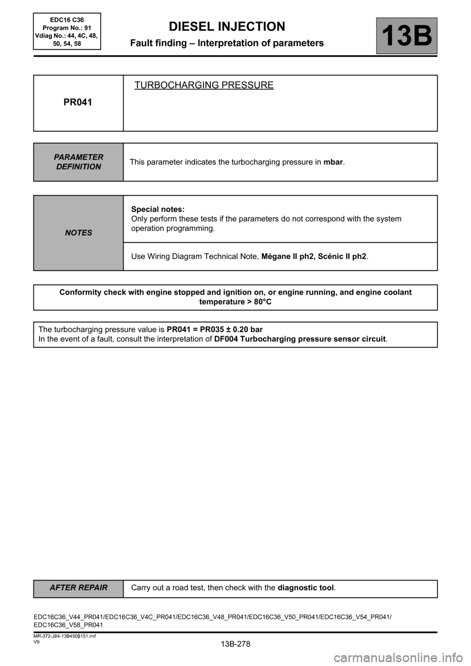
13B-278
AFTER REPAIRCarry out a road test, then check with the diagnostic tool.
V9 MR-372-J84-13B450$151.mif
DIESEL INJECTION
Fault finding – Interpretation of parameters13B
PR041TURBOCHARGING PRESSURE
PARAMETER
DEFINITIONThis parameter indicates the turbocharging pressure in mbar.
NOTESSpecial notes:
Only perform these tests if the parameters do not correspond with the system
operation programming.
Use Wiring Diagram Technical Note, Mégane II ph2, Scénic II ph2.
Conformity check with engine stopped and ignition on, or engine running, and engine coolant
temperature > 80°C
The turbocharging pressure value is PR041 = PR035 ± 0.20 bar
In the event of a fault, consult the interpretation of DF004 Turbocharging pressure sensor circuit.
EDC16C36_V44_PR041/EDC16C36_V4C_PR041/EDC16C36_V48_PR041/EDC16C36_V50_PR041/EDC16C36_V54_PR041/
EDC16C36_V58_PR041EDC16 C36
Program No.: 91
Vdiag No.: 44, 4C, 48,
50, 54, 58