filter RENAULT SCENIC 2011 J95 / 3.G Engine And Peripherals EDC16C36 Owner's Manual
[x] Cancel search | Manufacturer: RENAULT, Model Year: 2011, Model line: SCENIC, Model: RENAULT SCENIC 2011 J95 / 3.GPages: 431, PDF Size: 2.03 MB
Page 49 of 431
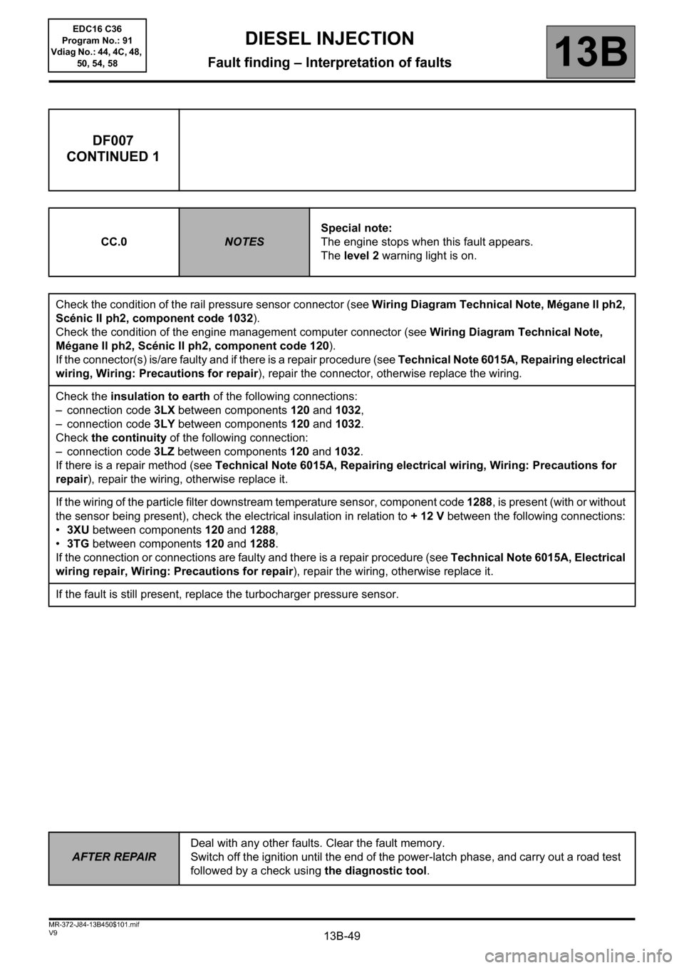
13B-49V9 MR-372-J84-13B450$101.mif
DIESEL INJECTION
Fault finding – Interpretation of faults13B
DF007
CONTINUED 1
CC.0NOTESSpecial note:
The engine stops when this fault appears.
The level 2 warning light is on.
Check the condition of the rail pressure sensor connector (see Wiring Diagram Technical Note, Mégane II ph2,
Scénic II ph2, component code 1032).
Check the condition of the engine management computer connector (see Wiring Diagram Technical Note,
Mégane II ph2, Scénic II ph2, component code 120).
If the connector(s) is/are faulty and if there is a repair procedure (see Technical Note 6015A, Repairing electrical
wiring, Wiring: Precautions for repair), repair the connector, otherwise replace the wiring.
Check the insulation to earth of the following connections:
– connection code 3LX between components 120 and 1032,
– connection code 3LY between components 120 and 1032.
Check the continuity of the following connection:
– connection code 3LZ between components 120 and 1032.
If there is a repair method (see Technical Note 6015A, Repairing electrical wiring, Wiring: Precautions for
repair), repair the wiring, otherwise replace it.
If the wiring of the particle filter downstream temperature sensor, component code 1288, is present (with or without
the sensor being present), check the electrical insulation in relation to + 12 V between the following connections:
•3XU between components 120 and 1288,
•3TG between components 120 and 1288.
If the connection or connections are faulty and there is a repair procedure (see Technical Note 6015A, Electrical
wiring repair, Wiring: Precautions for repair), repair the wiring, otherwise replace it.
If the fault is still present, replace the turbocharger pressure sensor.
AFTER REPAIRDeal with any other faults. Clear the fault memory.
Switch off the ignition until the end of the power-latch phase, and carry out a road test
followed by a check using the diagnostic tool.
EDC16 C36
Program No.: 91
Vdiag No.: 44, 4C, 48,
50, 54, 58
Page 87 of 431

13B-87V9 MR-372-J84-13B450$102.mif
DIESEL INJECTION
Fault finding – Interpretation of faults13B
DF053
CONTINUED
In the event of rail overpressure:
Check the operation of the injectors (see Test 10 Incorrect injector operation).
Display parameter PR038 Rail pressure and refer to the conformity check to check the conformity of the operating
values.
If these checks do not indicate any abnormality and if the fault persists, replace the injection pump.
In the event of rail vacuum pressure:
Check that the rail pressure sensor is operating correctly using command AC011 Rail pressure regulator. Display
parameter PR038 Rail pressure and refer to the conformity check to check the conformity of the operating values.
Check the priming of the low-pressure diesel circuit.
Check the conformity of the diesel filter connections.
Check the condition of the filter (clogging and water saturation).
Check that there are no air bubbles between the filter and the high pressure pump.
Check the seal of the low and high pressure diesel circuits (visual checks, odour, etc.), pump body, overpressure
valve, pipes, rail and injector unions, injector wells, etc.
Check the operation of the injectors (see Test 10 Incorrect injector operation).
Carry out the necessary operations.
If the fault is still present, replace the injection pump.
AFTER REPAIRDeal with any other faults. Clear the fault memory.
Switch off the ignition until the end of the power-latch phase, and carry out a road test
followed by a check using the diagnostic tool.
EDC16 C36
Program No.: 91
Vdiag No.: 44, 4C, 48,
50, 54, 58
Page 114 of 431
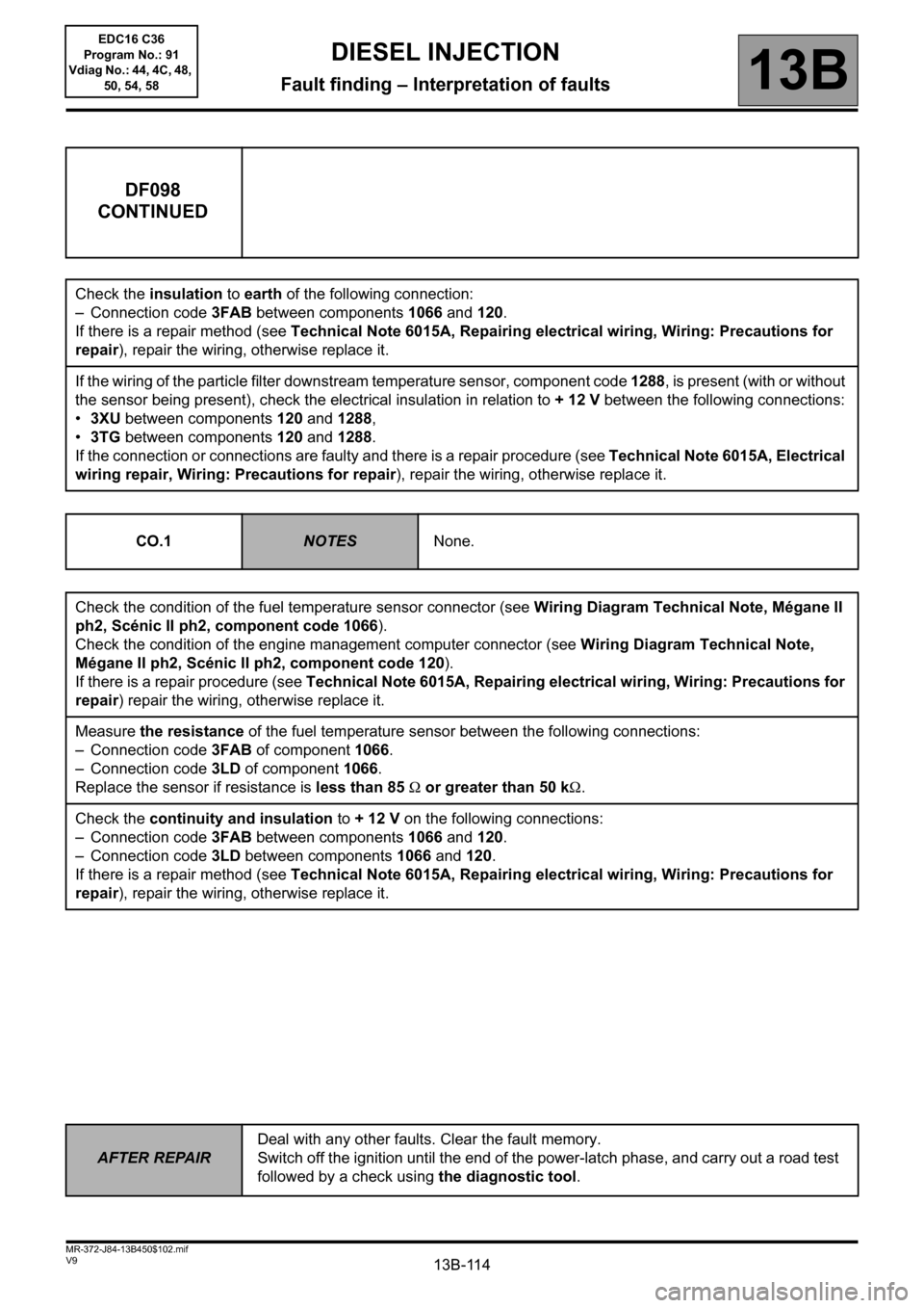
13B-114V9 MR-372-J84-13B450$102.mif
DIESEL INJECTION
Fault finding – Interpretation of faults13B
DF098
CONTINUED
Check the insulation to earth of the following connection:
– Connection code 3FAB between components 1066 and 120.
If there is a repair method (see Technical Note 6015A, Repairing electrical wiring, Wiring: Precautions for
repair), repair the wiring, otherwise replace it.
If the wiring of the particle filter downstream temperature sensor, component code 1288, is present (with or without
the sensor being present), check the electrical insulation in relation to + 12 V between the following connections:
•3XU between components 120 and 1288,
•3TG between components 120 and 1288.
If the connection or connections are faulty and there is a repair procedure (see Technical Note 6015A, Electrical
wiring repair, Wiring: Precautions for repair), repair the wiring, otherwise replace it.
CO.1
NOTESNone.
Check the condition of the fuel temperature sensor connector (see Wiring Diagram Technical Note, Mégane II
ph2, Scénic II ph2, component code 1066).
Check the condition of the engine management computer connector (see Wiring Diagram Technical Note,
Mégane II ph2, Scénic II ph2, component code 120).
If there is a repair procedure (see Technical Note 6015A, Repairing electrical wiring, Wiring: Precautions for
repair) repair the wiring, otherwise replace it.
Measure the resistance of the fuel temperature sensor between the following connections:
– Connection code 3FAB of component 1066.
– Connection code 3LD of component 1066.
Replace the sensor if resistance is less than 85Ω or greater than 50 kΩ.
Check the continuity and insulation to + 12 V on the following connections:
– Connection code 3FAB between components 1066 and 120.
– Connection code 3LD between components 1066 and 120.
If there is a repair method (see Technical Note 6015A, Repairing electrical wiring, Wiring: Precautions for
repair), repair the wiring, otherwise replace it.
AFTER REPAIRDeal with any other faults. Clear the fault memory.
Switch off the ignition until the end of the power-latch phase, and carry out a road test
followed by a check using the diagnostic tool.
EDC16 C36
Program No.: 91
Vdiag No.: 44, 4C, 48,
50, 54, 58
Page 116 of 431

13B-116V9 MR-372-J84-13B450$102.mif
DIESEL INJECTION
Fault finding – Interpretation of faults13B
DF107
CONTINUED
Only for F9Q816:
If the vehicle is not new (mileage greater than 10 km):
Check that there are no leaks or blockages in the exhaust pipe,
Repair if necessary
– Do an after-sales regeneration using the control SC017 Particle filter regeneration.
– Perform an oil change (see MR 364 (Mégane II) or MR 370 (Scénic II), Mechanical, 10A Engine and
peripherals, Engine oil: Draining – Filling).
If the fault is still present, contact the Techline.
Page 150 of 431
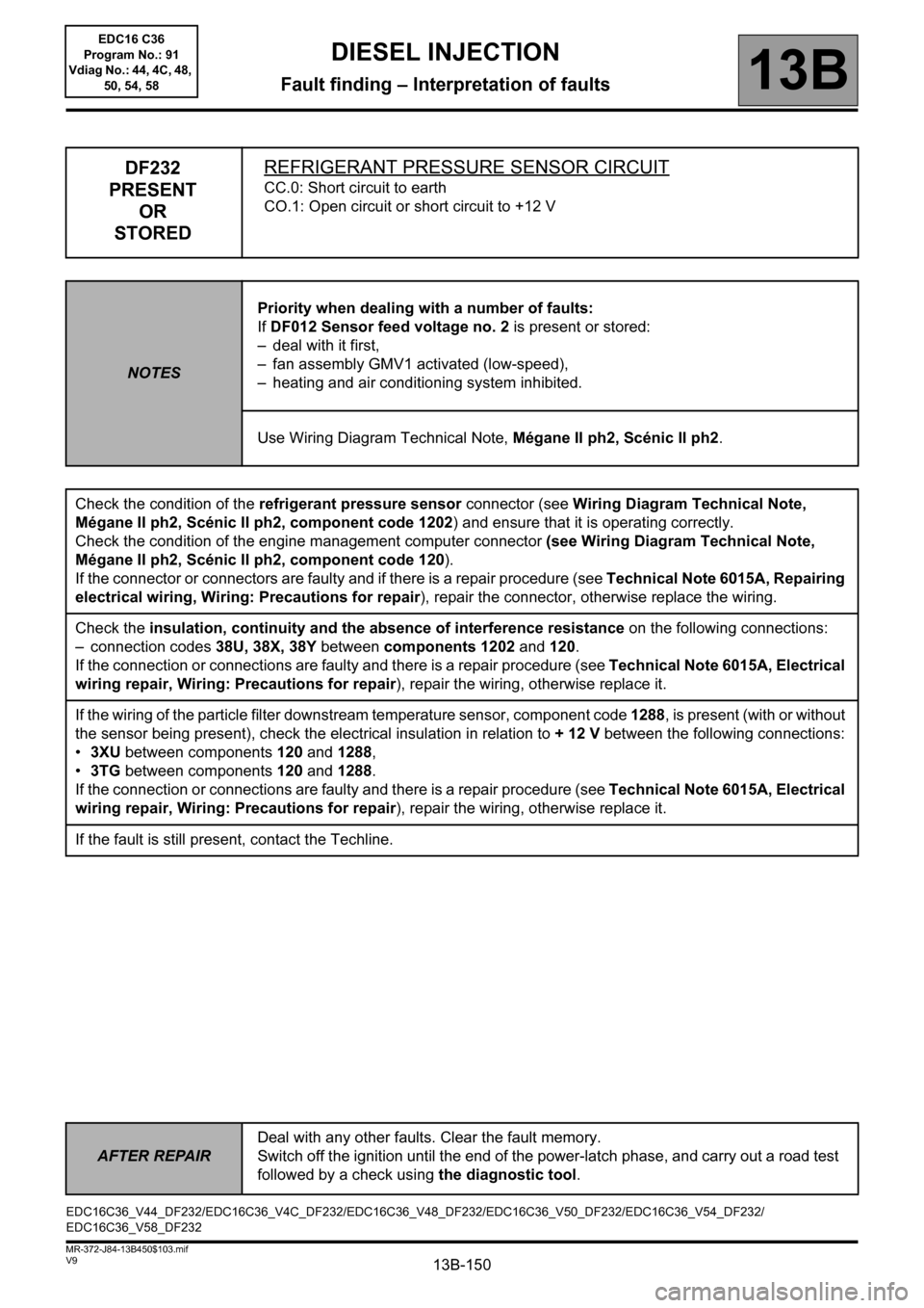
13B-150
AFTER REPAIRDeal with any other faults. Clear the fault memory.
Switch off the ignition until the end of the power-latch phase, and carry out a road test
followed by a check using the diagnostic tool.
V9 MR-372-J84-13B450$103.mif
DIESEL INJECTION
Fault finding – Interpretation of faults13B
DF232
PRESENT
OR
STOREDREFRIGERANT PRESSURE SENSOR CIRCUIT
CC.0: Short circuit to earth
CO.1: Open circuit or short circuit to +12 V
NOTESPriority when dealing with a number of faults:
If DF012 Sensor feed voltage no. 2 is present or stored:
– deal with it first,
– fan assembly GMV1 activated (low-speed),
– heating and air conditioning system inhibited.
Use Wiring Diagram Technical Note, Mégane II ph2, Scénic II ph2.
Check the condition of the refrigerant pressure sensor connector (see Wiring Diagram Technical Note,
Mégane II ph2, Scénic II ph2, component code 1202) and ensure that it is operating correctly.
Check the condition of the engine management computer connector (see Wiring Diagram Technical Note,
Mégane II ph2, Scénic II ph2, component code 120).
If the connector or connectors are faulty and if there is a repair procedure (see Technical Note 6015A, Repairing
electrical wiring, Wiring: Precautions for repair), repair the connector, otherwise replace the wiring.
Check the insulation, continuity and the absence of interference resistance on the following connections:
– connection codes 38U, 38X, 38Y between components 1202 and 120.
If the connection or connections are faulty and there is a repair procedure (see Technical Note 6015A, Electrical
wiring repair, Wiring: Precautions for repair), repair the wiring, otherwise replace it.
If the wiring of the particle filter downstream temperature sensor, component code 1288, is present (with or without
the sensor being present), check the electrical insulation in relation to + 12 V between the following connections:
•3XU between components 120 and 1288,
•3TG between components 120 and 1288.
If the connection or connections are faulty and there is a repair procedure (see Technical Note 6015A, Electrical
wiring repair, Wiring: Precautions for repair), repair the wiring, otherwise replace it.
If the fault is still present, contact the Techline.
EDC16C36_V44_DF232/EDC16C36_V4C_DF232/EDC16C36_V48_DF232/EDC16C36_V50_DF232/EDC16C36_V54_DF232/
EDC16C36_V58_DF232EDC16 C36
Program No.: 91
Vdiag No.: 44, 4C, 48,
50, 54, 58
Page 160 of 431

13B-160
AFTER REPAIRDeal with any other faults. Clear the fault memory.
Switch off the ignition until the end of the power-latch phase, and carry out a road test
followed by a check using the diagnostic tool.
V9 MR-372-J84-13B450$103.mif
DIESEL INJECTION
Fault finding – Interpretation of faults13B
DF293
CONTINUED
Make sure that there is no water in the diesel filter.
Bleed the diesel filter and the low and high pressure diesel circuits, if necessary (see MR 364 (Mégane) or 370
(Scénic), Mechanical, 13A, Fuel supply, and 13B, Diesel injection).
If the diesel filter contains a large amount of water, apply the first part of the Test 11: Diesel fuel conformity check
(Is the fuel cloudy or does it separate into 2 parts?)
Start the engine and wait at least 1 minute to confirm the repair.
If the fault was stored but not present, carry out a road test (see Note).
If the fault does not reappear, end of fault finding procedure.
Check the continuity, insulation and the absence of interference resistance of the following connection:
– Connection code 3WT between components 414 and 120.
Check the +12 V after relay feed of the water detection sensor:
– Connection code3FB of component414.
Check the earth of the water detection sensor:
– Connection code NT of component 414.
If there is a repair method (see Technical Note 6015A, Repairing electrical wiring, Wiring: Precautions for
repair), repair the wiring, otherwise replace it.
– Start the engine and wait at least 1 minute to confirm the repair.
Check the conformity of the fuel used by running test 11 Diesel fuel conformity check.
If none of these checks reveal any faults:
– Replace the water detection sensor,
– clear the fault,
– start the engine and wait at least 1 minute to confirm the repair.
Note:
When the water level in the fuel filter unit is below the sensor's electrodes, some driving conditions (cornering,
gradients) may result in water being detected (in fact, the sensor's off-centre position in the fuel filter unit, combined
with the driving conditions, causes water to be detected).
EDC16 C36
Program No.: 91
Vdiag No.: 44, 4C, 48,
50, 54, 58
Page 161 of 431
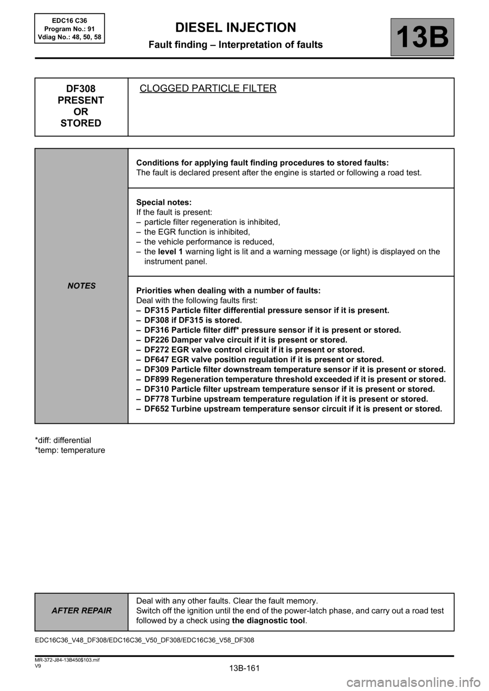
13B-161
AFTER REPAIRDeal with any other faults. Clear the fault memory.
Switch off the ignition until the end of the power-latch phase, and carry out a road test
followed by a check using the diagnostic tool.
V9 MR-372-J84-13B450$103.mif
DIESEL INJECTION
Fault finding – Interpretation of faults13B
*diff: differential
*temp: temperature
DF308
PRESENT
OR
STOREDCLOGGED PARTICLE FILTER
NOTESConditions for applying fault finding procedures to stored faults:
The fault is declared present after the engine is started or following a road test.
Special notes:
If the fault is present:
– particle filter regeneration is inhibited,
– the EGR function is inhibited,
– the vehicle performance is reduced,
–the level 1 warning light is lit and a warning message (or light) is displayed on the
instrument panel.
Priorities when dealing with a number of faults:
Deal with the following faults first:
– DF315 Particle filter differential pressure sensor if it is present.
– DF308 if DF315 is stored.
– DF316 Particle filter diff* pressure sensor if it is present or stored.
– DF226 Damper valve circuit if it is present or stored.
– DF272 EGR valve control circuit if it is present or stored.
– DF647 EGR valve position regulation if it is present or stored.
– DF309 Particle filter downstream temperature sensor if it is present or stored.
– DF899 Regeneration temperature threshold exceeded if it is present or stored.
– DF310 Particle filter upstream temperature sensor if it is present or stored.
– DF778 Turbine upstream temperature regulation if it is present or stored.
– DF652 Turbine upstream temperature sensor circuit if it is present or stored.
EDC16C36_V48_DF308/EDC16C36_V50_DF308/EDC16C36_V58_DF308EDC16 C36
Program No.: 91
Vdiag No.: 48, 50, 58
Page 162 of 431

13B-162
AFTER REPAIRDeal with any other faults. Clear the fault memory.
Switch off the ignition until the end of the power-latch phase, and carry out a road test
followed by a check using the diagnostic tool.
V9 MR-372-J84-13B450$103.mif
DIESEL INJECTION
Fault finding – Interpretation of faults13B
DF308
CONTINUED
Check that there are no leaks or blockages in the exhaust pipe,
Repair if necessary
Carry out an After-Sales regeneration.
Run command SC017 "Particle filter regeneration" (see Interpretation of commands).
Clear fault DF308 Present or Stored.
Apply TEST 4 Turbocharged air inlet circuit check.
If the fault is still present, contact the Techline.
EDC16 C36
Program No.: 91
Vdiag No.: 48, 58
Page 163 of 431

13B-163
AFTER REPAIRDeal with any other faults. Clear the fault memory.
Switch off the ignition until the end of the power-latch phase, and carry out a road test
followed by a check using the diagnostic tool.
V9 MR-372-J84-13B450$103.mif
DIESEL INJECTION
Fault finding – Interpretation of faults13B
*temp: temperature
DF309
PRESENT
OR
STOREDPARTICLE FILTER DOWNSTREAM TEMP.* SENSOR
CO.1: Open circuit or short circuit to +12 V
CC.0: Short circuit to earth
NOTESConditions for applying fault finding procedures to stored faults:
The fault becomes present if:
– ignition is on (CC.0),
– following a road test, engine warm (CO.1).
IMPORTANT
The particle filter downstream temperature sensor only measures temperatures
greater than 50°C.
Use the Wiring Diagram Technical Note, Mégane II ph2, Scénic II ph2.
CC.0
NOTESNone.
Check the condition of the particle filter downstream temperature sensor connector.
Check the condition of the engine management computer connector.
If the connector or connectors are faulty and if there is a repair procedure (see Technical Note 6015A, Repairing
electrical wiring, Wiring: Precautions for repair), repair the connector, otherwise replace the wiring.
Check the insulation from earth of the following connections:
– connection code3TG,
– connection code3XU,
between components 120 and 1288.
If the connection or connections are faulty and there is a repair procedure (see Technical Note 6015A, Electrical
wiring repair, Wiring: Precautions for repair), repair the wiring, otherwise replace it.
If the fault is still present, replace the particle filter downstream temperature sensor.
EDC16C36_V48_DF309/EDC16C36_V58_DF309EDC16 C36
Program No.: 91
Vdiag No.: 48, 58
Page 164 of 431
13B-164
AFTER REPAIRDeal with any other faults. Clear the fault memory.
Switch off the ignition until the end of the power-latch phase, and carry out a road test
followed by a check using the diagnostic tool.
V9 MR-372-J84-13B450$103.mif
DIESEL INJECTION
Fault finding – Interpretation of faults13B
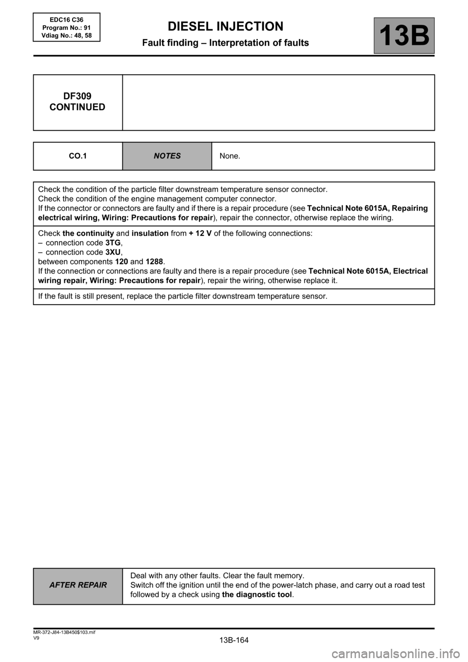
DF309
CONTINUED
CO.1NOTESNone.
Check the condition of the particle filter downstream temperature sensor connector.
Check the condition of the engine management computer connector.
If the connector or connectors are faulty and if there is a repair procedure (see Technical Note 6015A, Repairing
electrical wiring, Wiring: Precautions for repair), repair the connector, otherwise replace the wiring.
Check the continuity and insulation from + 12 V of the following connections:
– connection code3TG,
– connection code3XU,
between components 120 and 1288.
If the connection or connections are faulty and there is a repair procedure (see Technical Note 6015A, Electrical
wiring repair, Wiring: Precautions for repair), repair the wiring, otherwise replace it.
If the fault is still present, replace the particle filter downstream temperature sensor.
EDC16 C36
Program No.: 91
Vdiag No.: 48, 58