DF1 RENAULT SCENIC 2011 J95 / 3.G Engine And Peripherals EDC16C36 Workshop Manual
[x] Cancel search | Manufacturer: RENAULT, Model Year: 2011, Model line: SCENIC, Model: RENAULT SCENIC 2011 J95 / 3.GPages: 431, PDF Size: 2.03 MB
Page 25 of 431

13B-25V9 MR-372-J84-13B450$050.mif
DIESEL INJECTION
Fault finding – Features13B
EDC16 C36
Program No.: 91
Vdiag No.: 44, 4C, 48,
50, 54, 58
– DF056 Air flowmeter circuit.
– DF107 Computer memory.
– DF200 Atmospheric pressure sensor.
– DF209 EGR valve position sensor circuit.
– DF272 EGR valve control circuit.
– DF310 Particle filter upstream temp.* sensor
– DF315 Particle filter diff.* pressure sensor
– DF316 Particle filter diff* pressure
– DF647 EGR valve position regulation.
Some repair operations require programming to ensure that certain engine components function correctly.
Follow the programming procedures (see Replacement of components), if replacing the exhaust gas
recirculation valve or an injector.
*temp: temperature
* diff: differential
3. Conditions for deleting an OBD fault
An OBD fault is deleted in several phases.
The fault present on the diagnostic tool will only become stored (after a repair operation) after the vehicle has
been driven 3 times.
The OBD warning light will only go out after these 3 trips.
The instrument panel warning light coming on does not automatically mean that the system has a fault.
In order for the OBD fault and display parameters to be cleared from the computer, the system requires
40 engine heating cycles.
An engine heating cycle is a driving cycle during which:
– the engine coolant temperature reaches at least 71.1°C,
– the engine coolant temperature varies by 22.2°C in relation to the engine starting temperature.
If one of these conditions is not fulfilled, the OBD fault will still be present or stored on the injection
computer.
Page 36 of 431

13B-36V9 MR-372-J84-13B450$090.mif
DIESEL INJECTION
Fault finding – Fault summary table13B
EDC16 C36
Program No.: 91
Vdiag No.: 44, 4C, 48,
50, 54, 58
FaultDTC code in
hexadecimalLevel 1 fault
warning light
(orange
SERVICE
warning light)Level 2 fault
warning light
(red STOP
warning light)No fault
warning
light litOBD
warning
light lit
DF060 Misfiring on cylinder 2 302 - - 1.DEF -
DF061 Misfiring on cylinder 3 303 - - 1.DEF -
DF062 Misfiring on cylinder 4 304 - - 1.DEF -
DF065 Combustion misfire 300 - - 1.DEF -
DF069 Impact detected signal 1620 - 1.DEF - -
DF086 Coolant pump relay
control circuit2600CC.1/CC.0/
CO/ 1.DEF---
DF091 Vehicle speed signal 500 - - 1.DEF -
DF098 Fuel temperature
sensor circuit180 - - CC.0/CO.1 -
DF107 Computer memory 62F 1.DEF - - 1.DEF
DF119 Camshaft sensor
signal340 1.DEF/2.DEF - - -
DF120 Engine speed sensor
signal335 - 1.DEF/2.DEF - -
DF151 Main relay circuit 685 1.DEF/2.DEF - - -
DF165 Accelerator pedal
position sensor circuit2299 - 1.DEF/2.DEF 3.DEF -
DF195 Camshaft/engine
speed sensor consistency16 - - 1.DEF -
DF196 Pedal sensor circuit
gang 1225CO.0/CC.1/
1.DEF---
DF198 Pedal sensor circuit
gang 22120CO.0/CC.1/
1.DEF---
Page 39 of 431

13B-39V9 MR-372-J84-13B450$090.mif
DIESEL INJECTION
Fault finding – Fault summary table13B
EDC16 C36
Program No.: 91
Vdiag No.: 44, 4C, 48,
50, 54, 58
* regener: regenerationFaultDTC code in
hexadecimalLevel 1 fault
warning light
(orange
SERVICE
warning light)Level 2 fault
warning light
(red STOP
warning light)No fault
warning
light litOBD
warning
light lit
DF890 Movement during
particle filter regener.* 297 - - X -
DF891 Group 1 injectors feed 2146 - 1.DEF/2.DEF - -
DF892 Group 2 injectors feed 2149 - 1.DEF/2.DEF - -
DF899 Regeneration
temperature threshold limit
exceeded 3031 1.DEF
DF953 Particle filter absent 2002 - - X
DF967 Richness ratio sensor
circuit130 - -CC.0/CC.1/
CO/1.DEF/
2.DEF/
3.DEF-
DF970 Richness ratio sensor
heater circuit135 - -CC.0/CC.1/
CO/1.DEF/
2.DEF/
3.DEF-
DF980 Richness ratio sensor
function2A00 - -1.DEF/
2.DEF/
3.DEF-
DF1020 Engine oil dilution 253F 1.DEF - - -
Page 74 of 431
13B-74V9 MR-372-J84-13B450$101.mif
DIESEL INJECTION
Fault finding – Interpretation of faults13B
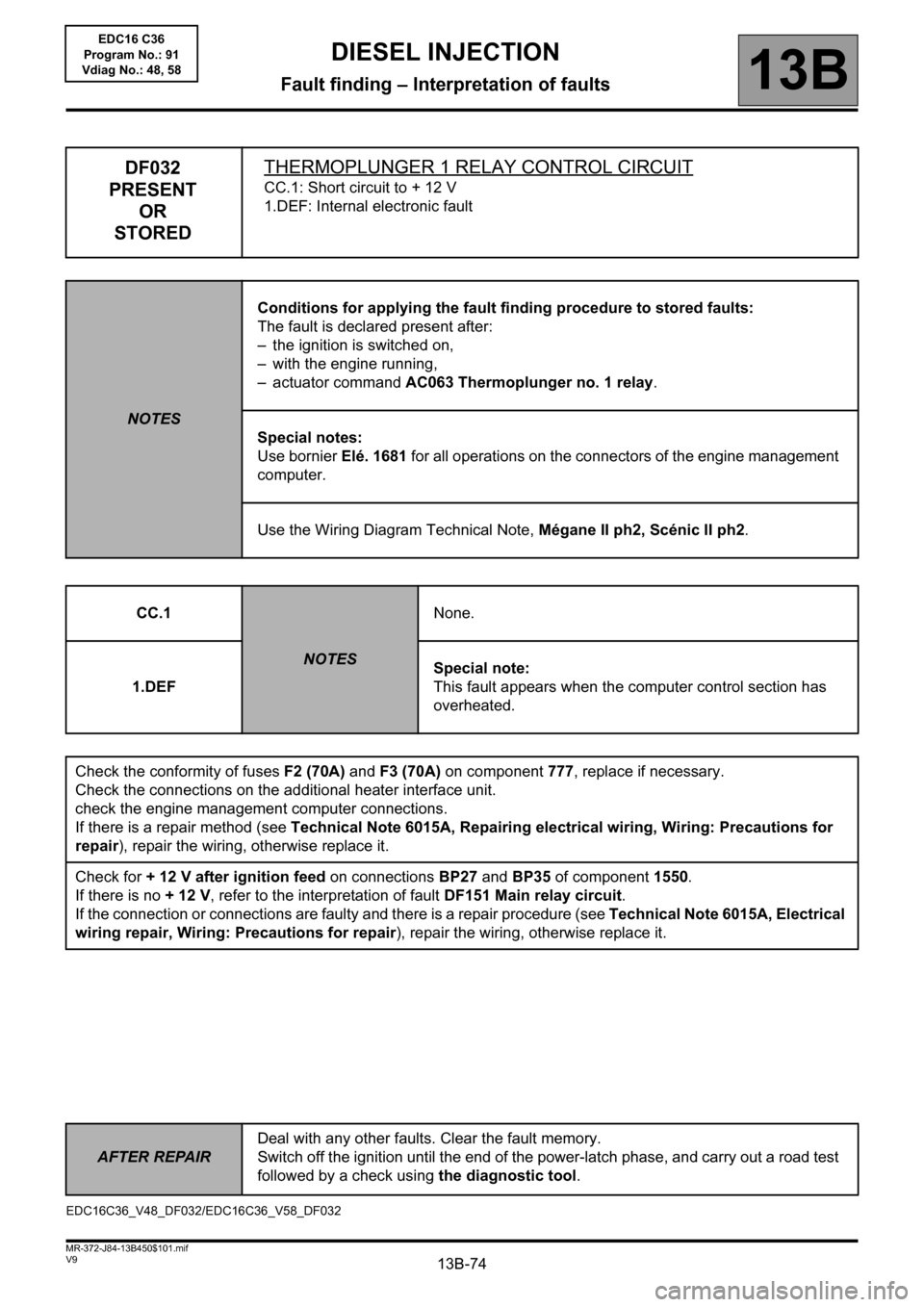
DF032
PRESENT
OR
STOREDTHERMOPLUNGER 1 RELAY CONTROL CIRCUIT
CC.1: Short circuit to + 12 V
1.DEF: Internal electronic fault
NOTESConditions for applying the fault finding procedure to stored faults:
The fault is declared present after:
– the ignition is switched on,
– with the engine running,
– actuator command AC063 Thermoplunger no. 1 relay.
Special notes:
Use bornier Elé. 1681 for all operations on the connectors of the engine management
computer.
Use the Wiring Diagram Technical Note, Mégane II ph2, Scénic II ph2.
CC.1
NOTESNone.
1.DEFSpecial note:
This fault appears when the computer control section has
overheated.
Check the conformity of fuses F2 (70A) and F3 (70A) on component 777, replace if necessary.
Check the connections on the additional heater interface unit.
check the engine management computer connections.
If there is a repair method (see Technical Note 6015A, Repairing electrical wiring, Wiring: Precautions for
repair), repair the wiring, otherwise replace it.
Check for + 12 V after ignition feed on connections BP27 and BP35 of component 1550.
If there is no + 12 V, refer to the interpretation of fault DF151 Main relay circuit.
If the connection or connections are faulty and there is a repair procedure (see Technical Note 6015A, Electrical
wiring repair, Wiring: Precautions for repair), repair the wiring, otherwise replace it.
EDC16C36_V48_DF032/EDC16C36_V58_DF032
AFTER REPAIRDeal with any other faults. Clear the fault memory.
Switch off the ignition until the end of the power-latch phase, and carry out a road test
followed by a check using the diagnostic tool.
EDC16 C36
Program No.: 91
Vdiag No.: 48, 58
Page 76 of 431
13B-76V9 MR-372-J84-13B450$101.mif
DIESEL INJECTION
Fault finding – Interpretation of faults13B
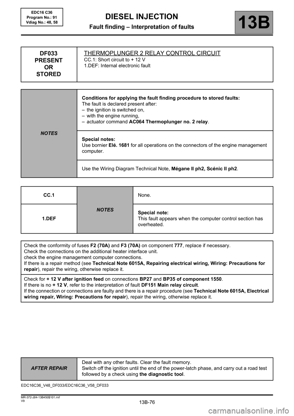
DF033
PRESENT
OR
STOREDTHERMOPLUNGER 2 RELAY CONTROL CIRCUIT
CC.1: Short circuit to + 12 V
1.DEF: Internal electronic fault
NOTESConditions for applying the fault finding procedure to stored faults:
The fault is declared present after:
– the ignition is switched on,
– with the engine running,
– actuator command AC064 Thermoplunger no. 2 relay.
Special notes:
Use bornier Elé. 1681 for all operations on the connectors of the engine management
computer.
Use the Wiring Diagram Technical Note, Mégane II ph2, Scénic II ph2.
CC.1
NOTESNone.
1.DEFSpecial note:
This fault appears when the computer control section has
overheated.
Check the conformity of fuses F2 (70A) and F3 (70A) on component 777, replace if necessary.
Check the connections on the additional heater interface unit.
check the engine management computer connections.
If there is a repair method (see Technical Note 6015A, Repairing electrical wiring, Wiring: Precautions for
repair), repair the wiring, otherwise replace it.
Check for + 12 V after ignition feed on connections BP27 and BP35 of component 1550.
If there is no + 12 V, refer to the interpretation of fault DF151 Main relay circuit.
If the connection or connections are faulty and there is a repair procedure (see Technical Note 6015A, Electrical
wiring repair, Wiring: Precautions for repair), repair the wiring, otherwise replace it.
EDC16C36_V48_DF033/EDC16C36_V58_DF033
AFTER REPAIRDeal with any other faults. Clear the fault memory.
Switch off the ignition until the end of the power-latch phase, and carry out a road test
followed by a check using the diagnostic tool.
EDC16 C36
Program No.: 91
Vdiag No.: 48, 58
Page 78 of 431
13B-78V9 MR-372-J84-13B450$101.mif
DIESEL INJECTION
Fault finding – Interpretation of faults13B
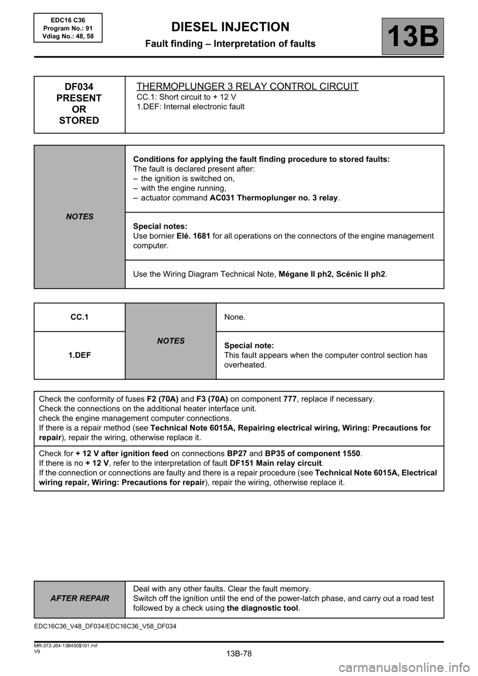
DF034
PRESENT
OR
STOREDTHERMOPLUNGER 3 RELAY CONTROL CIRCUIT
CC.1: Short circuit to + 12 V
1.DEF: Internal electronic fault
NOTESConditions for applying the fault finding procedure to stored faults:
The fault is declared present after:
– the ignition is switched on,
– with the engine running,
– actuator command AC031 Thermoplunger no. 3 relay.
Special notes:
Use bornier Elé. 1681 for all operations on the connectors of the engine management
computer.
Use the Wiring Diagram Technical Note, Mégane II ph2, Scénic II ph2.
CC.1
NOTESNone.
1.DEFSpecial note:
This fault appears when the computer control section has
overheated.
Check the conformity of fuses F2 (70A) and F3 (70A) on component 777, replace if necessary.
Check the connections on the additional heater interface unit.
check the engine management computer connections.
If there is a repair method (see Technical Note 6015A, Repairing electrical wiring, Wiring: Precautions for
repair), repair the wiring, otherwise replace it.
Check for + 12 V after ignition feed on connections BP27 and BP35 of component 1550.
If there is no + 12 V, refer to the interpretation of fault DF151 Main relay circuit.
If the connection or connections are faulty and there is a repair procedure (see Technical Note 6015A, Electrical
wiring repair, Wiring: Precautions for repair), repair the wiring, otherwise replace it.
EDC16C36_V48_DF034/EDC16C36_V58_DF034EDC16 C36
Program No.: 91
Vdiag No.: 48, 58
AFTER REPAIRDeal with any other faults. Clear the fault memory.
Switch off the ignition until the end of the power-latch phase, and carry out a road test
followed by a check using the diagnostic tool.
Page 85 of 431
13B-85V9 MR-372-J84-13B450$102.mif
DIESEL INJECTION
Fault finding – Interpretation of faults13B
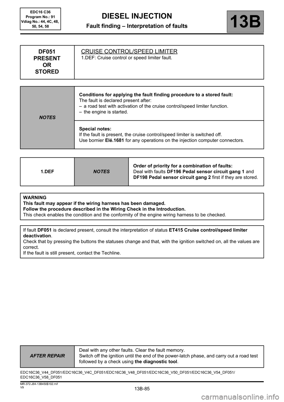
DF051
PRESENT
OR
STOREDCRUISE CONTROL/SPEED LIMITER
1.DEF: Cruise control or speed limiter fault.
NOTESConditions for applying the fault finding procedure to a stored fault:
The fault is declared present after:
– a road test with activation of the cruise control/speed limiter function.
– the engine is started.
Special notes:
If the fault is present, the cruise control/speed limiter is switched off.
Use bornier Elé.1681 for any operations on the injection computer connectors.
1.DEF
NOTESOrder of priority for a combination of faults:
Deal with faults DF196 Pedal sensor circuit gang 1 and
DF198 Pedal sensor circuit gang 2 first if they are stored.
WARNING
This fault may appear if the wiring harness has been damaged.
Follow the procedure described in the Wiring Check in the Introduction.
This check enables the condition and the conformity of the engine wiring harness to be checked.
If fault DF051 is declared present, consult the interpretation of status ET415 Cruise control/speed limiter
deactivation.
Check that by pressing the buttons the statuses change and that, with the ignition switched on, all the values are
correct.
If the fault is still present, contact the Techline.
EDC16C36_V44_DF051/EDC16C36_V4C_DF051/EDC16C36_V48_DF051/EDC16C36_V50_DF051/EDC16C36_V54_DF051/
EDC16C36_V58_DF051
AFTER REPAIRDeal with any other faults. Clear the fault memory.
Switch off the ignition until the end of the power-latch phase, and carry out a road test
followed by a check using the diagnostic tool.
EDC16 C36
Program No.: 91
Vdiag No.: 44, 4C, 48,
50, 54, 58
Page 115 of 431
13B-115V9 MR-372-J84-13B450$102.mif
DIESEL INJECTION
Fault finding – Interpretation of faults13B
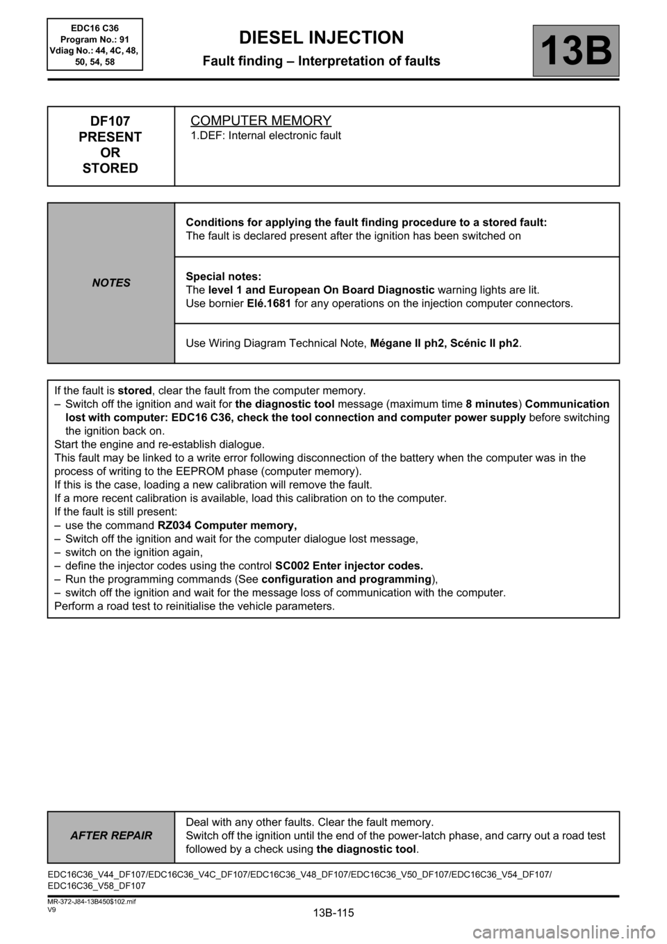
DF107
PRESENT
OR
STOREDCOMPUTER MEMORY
1.DEF: Internal electronic fault
NOTESConditions for applying the fault finding procedure to a stored fault:
The fault is declared present after the ignition has been switched on
Special notes:
The level 1 and European On Board Diagnostic warning lights are lit.
Use bornier Elé.1681 for any operations on the injection computer connectors.
Use Wiring Diagram Technical Note, Mégane II ph2, Scénic II ph2.
If the fault is stored, clear the fault from the computer memory.
– Switch off the ignition and wait for the diagnostic tool message (maximum time 8minutes) Communication
lost with computer: EDC16 C36, check the tool connection and computer power supply before switching
the ignition back on.
Start the engine and re-establish dialogue.
This fault may be linked to a write error following disconnection of the battery when the computer was in the
process of writing to the EEPROM phase (computer memory).
If this is the case, loading a new calibration will remove the fault.
If a more recent calibration is available, load this calibration on to the computer.
If the fault is still present:
– use the command RZ034 Computer memory,
– Switch off the ignition and wait for the computer dialogue lost message,
– switch on the ignition again,
– define the injector codes using the control SC002 Enter injector codes.
– Run the programming commands (See configuration and programming),
– switch off the ignition and wait for the message loss of communication with the computer.
Perform a road test to reinitialise the vehicle parameters.
EDC16C36_V44_DF107/EDC16C36_V4C_DF107/EDC16C36_V48_DF107/EDC16C36_V50_DF107/EDC16C36_V54_DF107/
EDC16C36_V58_DF107
AFTER REPAIRDeal with any other faults. Clear the fault memory.
Switch off the ignition until the end of the power-latch phase, and carry out a road test
followed by a check using the diagnostic tool.
EDC16 C36
Program No.: 91
Vdiag No.: 44, 4C, 48,
50, 54, 58
Page 116 of 431

13B-116V9 MR-372-J84-13B450$102.mif
DIESEL INJECTION
Fault finding – Interpretation of faults13B
DF107
CONTINUED
Only for F9Q816:
If the vehicle is not new (mileage greater than 10 km):
Check that there are no leaks or blockages in the exhaust pipe,
Repair if necessary
– Do an after-sales regeneration using the control SC017 Particle filter regeneration.
– Perform an oil change (see MR 364 (Mégane II) or MR 370 (Scénic II), Mechanical, 10A Engine and
peripherals, Engine oil: Draining – Filling).
If the fault is still present, contact the Techline.
Page 117 of 431
13B-117V9 MR-372-J84-13B450$102.mif
DIESEL INJECTION
Fault finding – Interpretation of faults13B
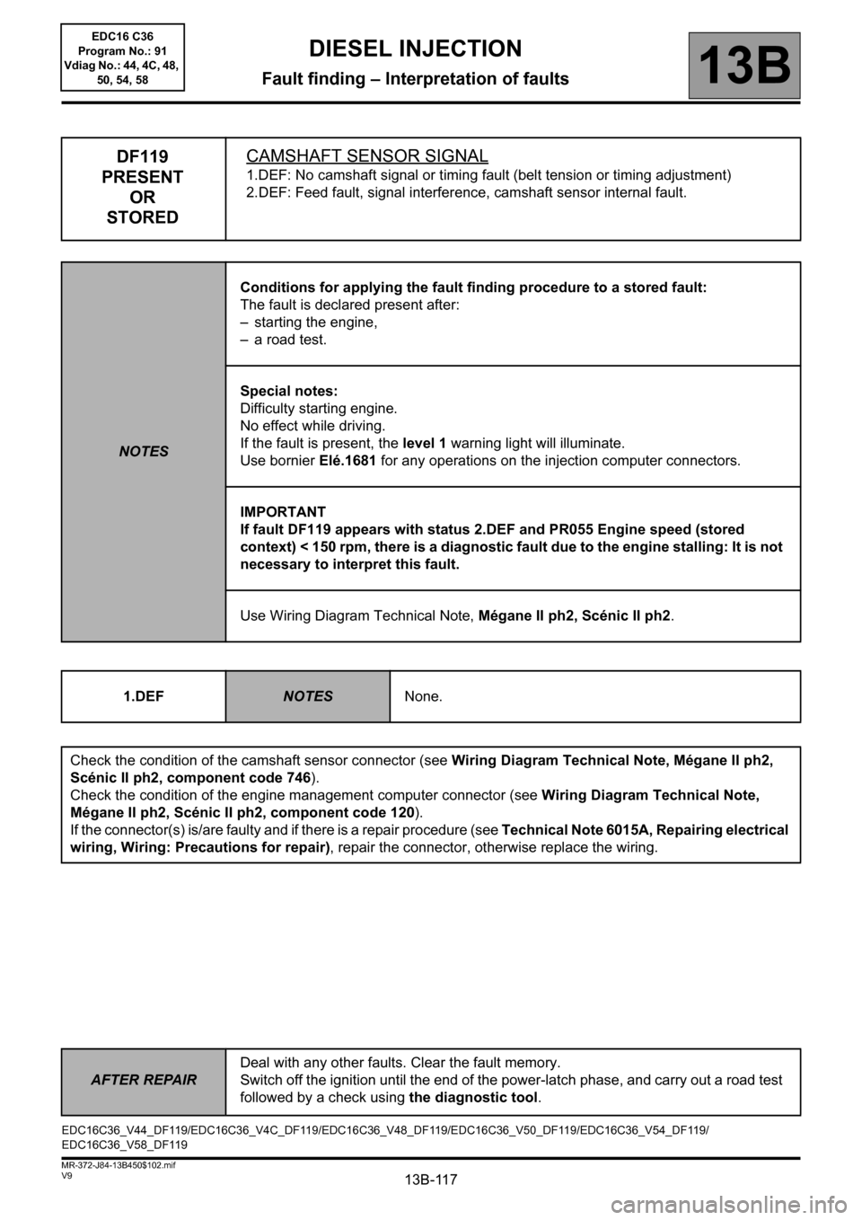
DF119
PRESENT
OR
STOREDCAMSHAFT SENSOR SIGNAL
1.DEF: No camshaft signal or timing fault (belt tension or timing adjustment)
2.DEF: Feed fault, signal interference, camshaft sensor internal fault.
NOTESConditions for applying the fault finding procedure to a stored fault:
The fault is declared present after:
– starting the engine,
– a road test.
Special notes:
Difficulty starting engine.
No effect while driving.
If the fault is present, the level 1 warning light will illuminate.
Use bornier Elé.1681 for any operations on the injection computer connectors.
IMPORTANT
If fault DF119 appears with status 2.DEF and PR055 Engine speed (stored
context) < 150 rpm, there is a diagnostic fault due to the engine stalling: It is not
necessary to interpret this fault.
Use Wiring Diagram Technical Note, Mégane II ph2, Scénic II ph2.
1.DEF
NOTESNone.
Check the condition of the camshaft sensor connector (see Wiring Diagram Technical Note, Mégane II ph2,
Scénic II ph2, component code 746).
Check the condition of the engine management computer connector (see Wiring Diagram Technical Note,
Mégane II ph2, Scénic II ph2, component code 120).
If the connector(s) is/are faulty and if there is a repair procedure (see Technical Note 6015A, Repairing electrical
wiring, Wiring: Precautions for repair), repair the connector, otherwise replace the wiring.
EDC16C36_V44_DF119/EDC16C36_V4C_DF119/EDC16C36_V48_DF119/EDC16C36_V50_DF119/EDC16C36_V54_DF119/
EDC16C36_V58_DF119
AFTER REPAIRDeal with any other faults. Clear the fault memory.
Switch off the ignition until the end of the power-latch phase, and carry out a road test
followed by a check using the diagnostic tool.
EDC16 C36
Program No.: 91
Vdiag No.: 44, 4C, 48,
50, 54, 58