cruise control RENAULT SCENIC 2011 J95 / 3.G Engine And Peripherals Siemens Injection User Guide
[x] Cancel search | Manufacturer: RENAULT, Model Year: 2011, Model line: SCENIC, Model: RENAULT SCENIC 2011 J95 / 3.GPages: 329, PDF Size: 1.71 MB
Page 46 of 329
13B-46
MR-372-J84-13B050$390.mif
V17
DIESEL INJECTION
Fault finding – Interpretation of faults
Siemens Injection
SID301 and 304
Vdiag No. 44-45-48-49-4D-4C
Program No.: B1 and B2
13B
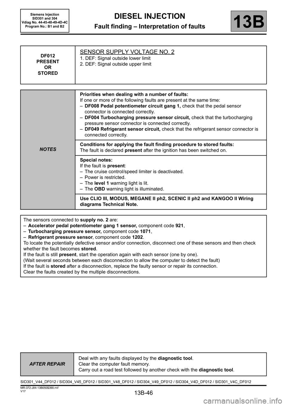
DF012
PRESENT
OR
STOREDSENSOR SUPPLY VOLTAGE NO. 2
1. DEF: Signal outside lower limit
2. DEF: Signal outside upper limit
NOTESPriorities when dealing with a number of faults:
If one or more of the following faults are present at the same time:
–DF008 Pedal potentiometer circuit gang 1, check that the pedal sensor
connector is connected correctly.
–DF004 Turbocharging pressure sensor circuit, check that the turbocharging
pressure sensor connector is connected correctly.
–DF049 Refrigerant sensor circuit, check that the refrigerant sensor connector is
connected correctly.
Conditions for applying the fault finding procedure to stored faults:
The fault is declared present after the ignition has been switched on.
Special notes:
If the fault is present:
– The cruise control/speed limiter is deactivated.
– Power is restricted.
–The level 1 warning light is lit.
–The OBD warning light is illuminated.
Use CLIO III, MODUS, MEGANE II ph2, SCENIC II ph2 and KANGOO II Wiring
diagrams Technical Note.
The sensors connected to supply no. 2 are:
–Accelerator pedal potentiometer gang 1 sensor, component code 921,
–Turbocharging pressure sensor, component code 1071,
–Refrigerant pressure sensor, component code 1202.
To locate the potentially defective sensor and/or connection, disconnect one of these sensors and then check
whether the fault becomes stored.
If the fault is still present, start the operation again with each sensor (one by one).
(Wait several seconds between each disconnection to allow the computer to detect the fault)
If the fault is stored after a disconnection, replace the faulty sensor or repair its connection.
Clear the faults created by the multiple disconnections.
AFTER REPAIRDeal with any faults displayed by the diagnostic tool.
Clear the computer fault memory.
Carry out a road test followed by another check with the diagnostic tool.
SID301_V44_DF012 / SID304_V45_DF012 / SID301_V48_DF012 / SID304_V49_DF012 / SID304_V4D_DF012 / SID301_V4C_DF012
Page 61 of 329
13B-61
MR-372-J84-13B050$390.mif
V17
DIESEL INJECTION
Fault finding – Interpretation of faults
Siemens Injection
SID301 and 304
Vdiag No. 44-45-48-49-4D-4C
Program No.: B1 and B2
13B
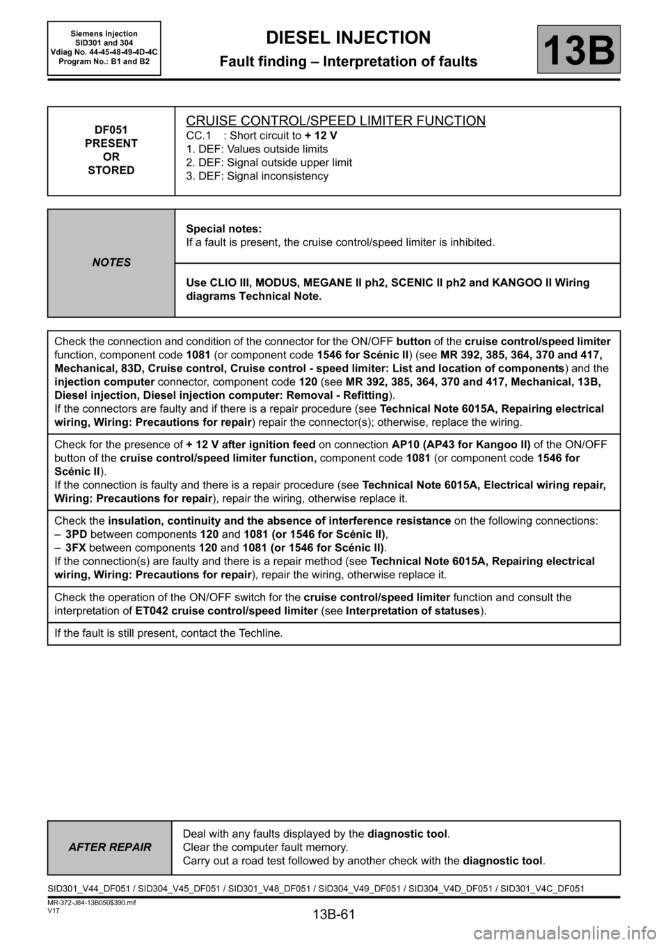
DF051
PRESENT
OR
STOREDCRUISE CONTROL/SPEED LIMITER FUNCTION
CC.1 : Short circuit to + 12 V
1. DEF: Values outside limits
2. DEF: Signal outside upper limit
3. DEF: Signal inconsistency
NOTESSpecial notes:
If a fault is present, the cruise control/speed limiter is inhibited.
Use CLIO III, MODUS, MEGANE II ph2, SCENIC II ph2 and KANGOO II Wiring
diagrams Technical Note.
Check the connection and condition of the connector for the ON/OFF button of the cruise control/speed limiter
function, component code1081 (or component code1546 for Scénic II) (see MR 392, 385, 364, 370 and 417,
Mechanical, 83D, Cruise control, Cruise control - speed limiter: List and location of components) and the
injection computer connector, component code120 (see MR 392, 385, 364, 370 and 417, Mechanical, 13B,
Diesel injection, Diesel injection computer: Removal - Refitting).
If the connectors are faulty and if there is a repair procedure (see Technical Note 6015A, Repairing electrical
wiring, Wiring: Precautions for repair) repair the connector(s); otherwise, replace the wiring.
Check for the presence of + 12 V after ignition feed on connection AP10 (AP43 for Kangoo II) of the ON/OFF
button of the cruise control/speed limiter function, component code 1081 (or component code 1546 for
Scénic II).
If the connection is faulty and there is a repair procedure (see Technical Note 6015A, Electrical wiring repair,
Wiring: Precautions for repair), repair the wiring, otherwise replace it.
Check the insulation, continuity and the absence of interference resistance on the following connections:
–3PD between components120 and 1081 (or 1546 for Scénic II),
–3FX between components120 and 1081 (or 1546 for Scénic II).
If the connection(s) are faulty and there is a repair method (see Technical Note 6015A, Repairing electrical
wiring, Wiring: Precautions for repair), repair the wiring, otherwise replace it.
Check the operation of the ON/OFF switch for the cruise control/speed limiter function and consult the
interpretation of ET042 cruise control/speed limiter (see Interpretation of statuses).
If the fault is still present, contact the Techline.
AFTER REPAIRDeal with any faults displayed by the diagnostic tool.
Clear the computer fault memory.
Carry out a road test followed by another check with the diagnostic tool.
SID301_V44_DF051 / SID304_V45_DF051 / SID301_V48_DF051 / SID304_V49_DF051 / SID304_V4D_DF051 / SID301_V4C_DF051
Page 89 of 329

13B-89
MR-372-J84-13B050$429.mif
V17
DIESEL INJECTION
Fault finding – Interpretation of faults
Siemens Injection
SID301 and 304
Vdiag No.: 44-45-48-49-4D-4C
Program No.: B1 and B2
13B
DF582
PRESENT
OR
STOREDPRESSURE CONSISTENCY
1. DEF: Signal outside lower limit
2. DEF: Signal outside upper limit
NOTESConditions for applying the fault finding procedure to a stored fault:
The fault becomes present after starting the engine.
If the fault is present:
–The level 1 and OBD fault warning lights are lit on the instrument panel.
–The cruise control/speed limiter is inhibited.
– Loss of performance, torque setpoint restricted.
Use CLIO III, MODUS, MEGANE II ph2, SCENIC II ph2 and KANGOO II Wiring
diagrams Technical Note.
Check the condition and connection of the turbocharging pressure sensor connector, component code 1071.
If the connector is faulty and there is a repair procedure (see Technical Note 6015A, Electrical wiring repair,
Wiring: Precautions for repair), repair the connector, otherwise replace the wiring.
Check the connection and condition of the injection computer connector, component code 120 (see MR 392,
385, 364, 370 and 417, Mechanical, 13B, Diesel injection, Diesel injection computer: Removal - Refitting).
If the connector is faulty and there is a repair procedure (see Technical Note 6015A, Electrical wiring repair,
Wiring: Precautions for repair), repair the connector, otherwise replace the wiring.
With the ignition on, check for + 5 V on connection 3LQ and earth on connection 3LN of the turbocharging
pressure sensor.
If the connection(s) are faulty and there is a repair method (see Technical Note 6015A, Repairing electrical
wiring, Wiring: Precautions for repair), repair the wiring, otherwise replace it.
Check the insulation, continuity and the absence of interference resistance on the following connections:
–3LQ between components 1071 and 120,
–3LN between components 1071 and 120,
–3LP between components 1071 and 120.
If the connection(s) are faulty and there is a repair method (see Technical Note 6015A, Repairing electrical
wiring, Wiring: Precautions for repair), repair the wiring, otherwise replace it.
Check the consistency between the atmospheric pressure and the turbocharging pressure (PR035
Atmospheric pressure = PR041 Turbocharging pressure
).
Engine stopped (cold), the pressure read by the two sensors must be nearly the same.
If the values are very different, replace the turbocharging pressure sensor.
If the fault is still present, contact the Techline.
AFTER REPAIRDeal with any faults displayed by the diagnostic tool.
Clear the computer fault memory.
Carry out a road test followed by another check with the diagnostic tool.
SID301_V44_DF582 / SID304_V45_DF582 / SID301_V48_DF582 / SID304_V49_DF582 / SID304_V4D_DF582 / SID301_V4C_DF582
Page 125 of 329
13B-125
MR-372-J84-13B050$546.mif
V17
13B
DIESEL INJECTION
Fault finding – Status summary table
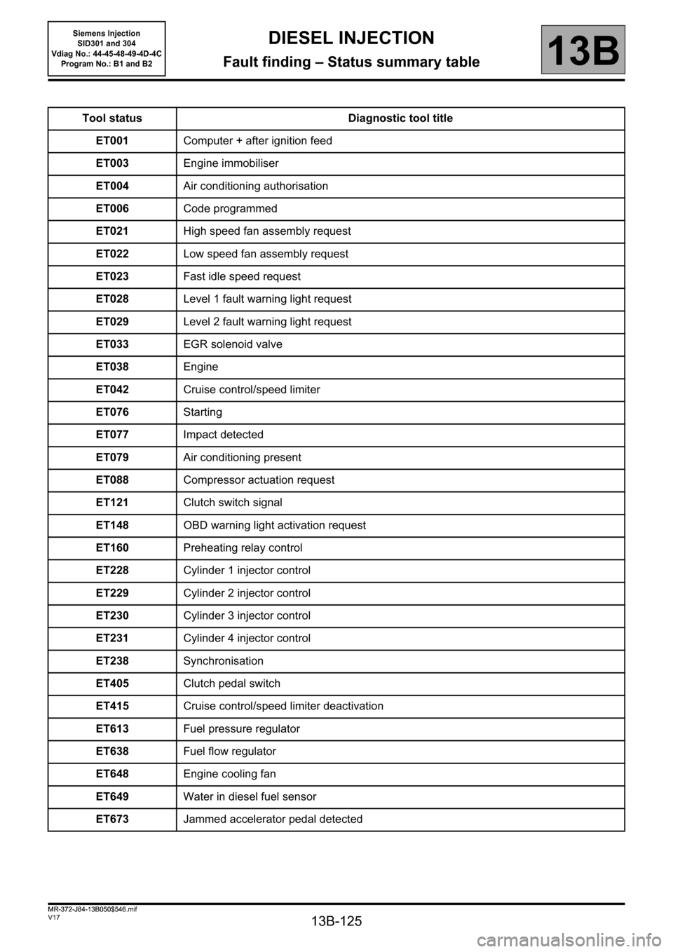
Tool status Diagnostic tool title
ET001Computer + after ignition feed
ET003Engine immobiliser
ET004 Air conditioning authorisation
ET006Code programmed
ET021High speed fan assembly request
ET022Low speed fan assembly request
ET023Fast idle speed request
ET028Level 1 fault warning light request
ET029Level 2 fault warning light request
ET033EGR solenoid valve
ET038Engine
ET042Cruise control/speed limiter
ET076Starting
ET077Impact detected
ET079Air conditioning present
ET088Compressor actuation request
ET121Clutch switch signal
ET148OBD warning light activation request
ET160Preheating relay control
ET228Cylinder 1 injector control
ET229Cylinder 2 injector control
ET230Cylinder 3 injector control
ET231Cylinder 4 injector control
ET238Synchronisation
ET405Clutch pedal switch
ET415Cruise control/speed limiter deactivation
ET613Fuel pressure regulator
ET638Fuel flow regulator
ET648Engine cooling fan
ET649Water in diesel fuel sensor
ET673Jammed accelerator pedal detected
MR-372-J84-13B050$546.mif
Siemens Injection
SID301 and 304
Vdiag No.: 44-45-48-49-4D-4C
Program No.: B1 and B2
Page 126 of 329
13B-126
MR-372-J84-13B050$546.mif
V17
Siemens Injection
SID301 and 304
Vdiag No.: 44-45-48-49-4D-4C
Program No.: B1 and B2DIESEL INJECTION
Fault finding – Status summary table13B
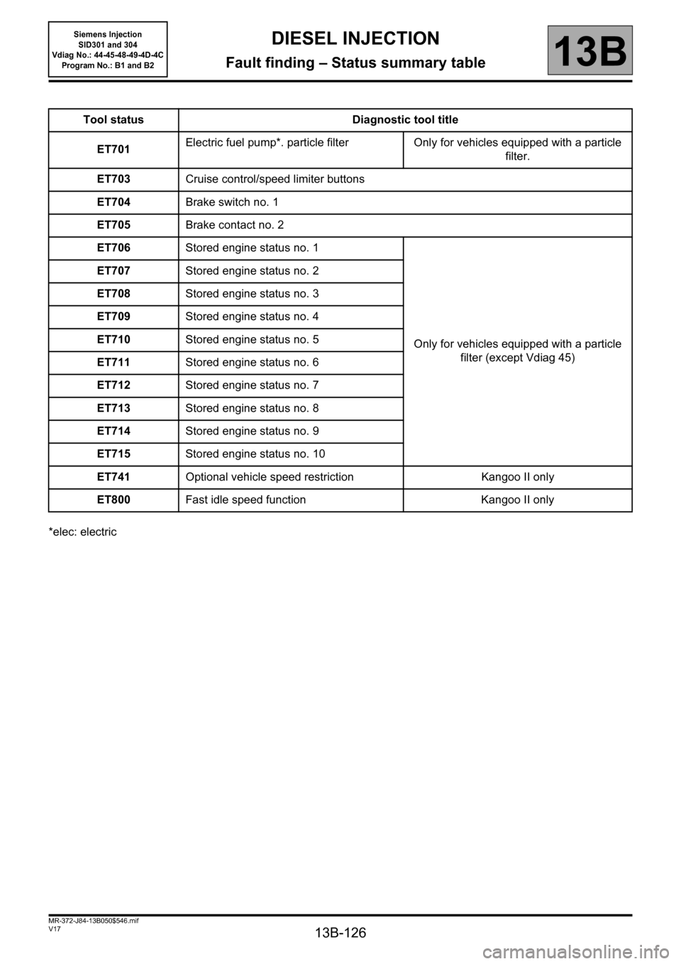
*elec: electricTool status Diagnostic tool title
ET701Electric fuel pump*. particle filter Only for vehicles equipped with a particle
filter.
ET703Cruise control/speed limiter buttons
ET704Brake switch no. 1
ET705Brake contact no. 2
ET706Stored engine status no. 1
Only for vehicles equipped with a particle
filter (except Vdiag 45) ET707Stored engine status no. 2
ET708Stored engine status no. 3
ET709Stored engine status no. 4
ET710Stored engine status no. 5
ET711Stored engine status no. 6
ET712Stored engine status no. 7
ET713Stored engine status no. 8
ET714Stored engine status no. 9
ET715Stored engine status no. 10
ET741Optional vehicle speed restriction Kangoo II only
ET800Fast idle speed function Kangoo II only
Page 139 of 329
13B-139
MR-372-J84-13B050$585.mif
V17
Siemens Injection
SID301 and 304
Vdiag No.: 44-45-48-49-4D-4C
Program No.: B1 and B2DIESEL INJECTION
Fault finding – Interpretation of statuses13B
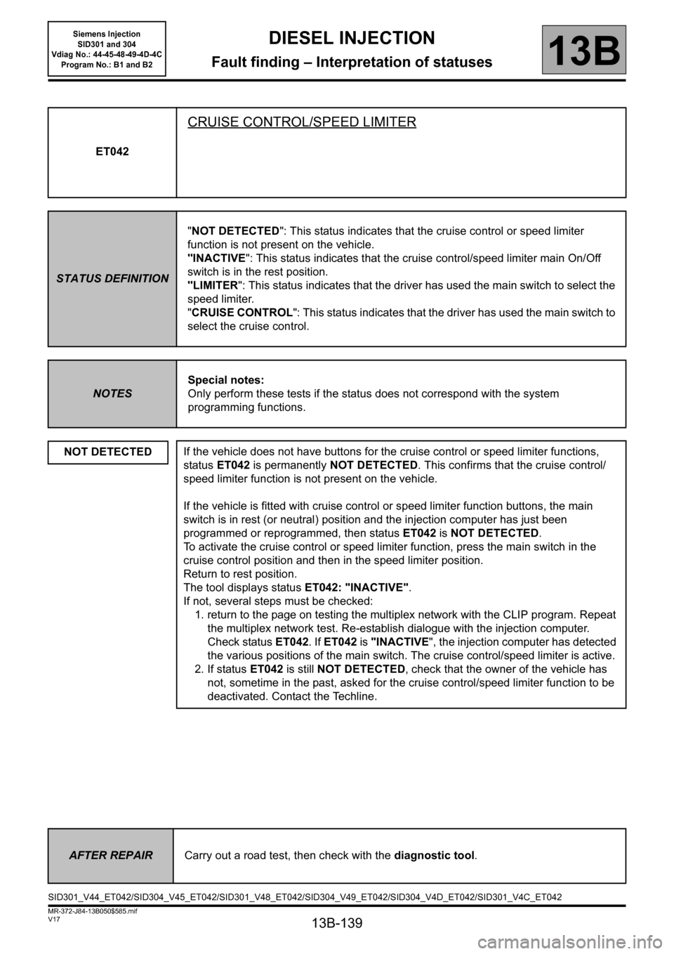
ET042
CRUISE CONTROL/SPEED LIMITER
STATUS DEFINITION"NOT DETECTED": This status indicates that the cruise control or speed limiter
function is not present on the vehicle.
"INACTIVE": This status indicates that the cruise control/speed limiter main On/Off
switch is in the rest position.
"LIMITER": This status indicates that the driver has used the main switch to select the
speed limiter.
"CRUISE CONTROL": This status indicates that the driver has used the main switch to
select the cruise control.
NOTESSpecial notes:
Only perform these tests if the status does not correspond with the system
programming functions.
NOT DETECTED
If the vehicle does not have buttons for the cruise control or speed limiter functions,
status ET042 is permanently NOT DETECTED. This confirms that the cruise control/
speed limiter function is not present on the vehicle.
If the vehicle is fitted with cruise control or speed limiter function buttons, the main
switch is in rest (or neutral) position and the injection computer has just been
programmed or reprogrammed, then status ET042 is NOT DETECTED.
To activate the cruise control or speed limiter function, press the main switch in the
cruise control position and then in the speed limiter position.
Return to rest position.
The tool displays status ET042: "INACTIVE".
If not, several steps must be checked:
1. return to the page on testing the multiplex network with the CLIP program. Repeat
the multiplex network test. Re-establish dialogue with the injection computer.
Check status ET042. If ET042 is "INACTIVE", the injection computer has detected
the various positions of the main switch. The cruise control/speed limiter is active.
2. If status ET042 is still NOT DETECTED, check that the owner of the vehicle has
not, sometime in the past, asked for the cruise control/speed limiter function to be
deactivated. Contact the Techline.
AFTER REPAIRCarry out a road test, then check with the diagnostic tool.
SID301_V44_ET042/SID304_V45_ET042/SID301_V48_ET042/SID304_V49_ET042/SID304_V4D_ET042/SID301_V4C_ET042
Page 140 of 329
13B-140
MR-372-J84-13B050$585.mif
V17
Siemens Injection
SID301 and 304
Vdiag No.: 44-45-48-49-4D-4C
Program No.: B1 and B2DIESEL INJECTION
Fault finding – Interpretation of statuses13B
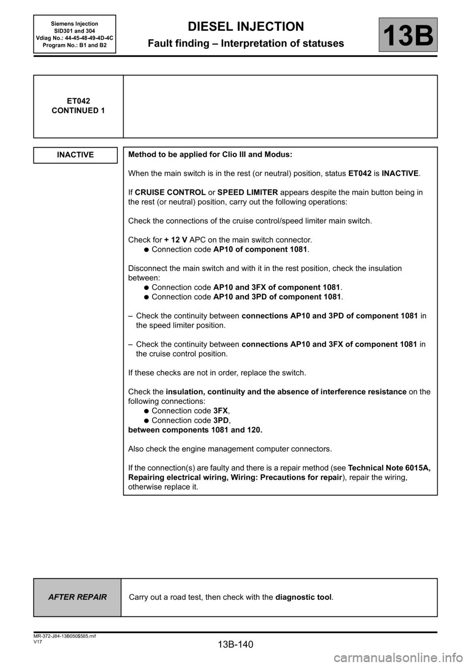
ET042
CONTINUED 1
INACTIVE
Method to be applied for Clio III and Modus:
When the main switch is in the rest (or neutral) position, status ET042 is INACTIVE.
If CRUISE CONTROL or SPEED LIMITER appears despite the main button being in
the rest (or neutral) position, carry out the following operations:
Check the connections of the cruise control/speed limiter main switch.
Check for + 12 V APC on the main switch connector.
●Connection code AP10 of component 1081.
Disconnect the main switch and with it in the rest position, check the insulation
between:
●Connection code AP10 and 3FX of component 1081.
●Connection code AP10 and 3PD of component 1081.
– Check the continuity between connections AP10 and 3PD of component 1081 in
the speed limiter position.
– Check the continuity between connections AP10 and 3FX of component 1081 in
the cruise control position.
If these checks are not in order, replace the switch.
Check the insulation, continuity and the absence of interference resistance on the
following connections:
●Connection code 3FX,
●Connection code 3PD,
between components 1081 and 120.
Also check the engine management computer connectors.
If the connection(s) are faulty and there is a repair method (see Technical Note 6015A,
Repairing electrical wiring, Wiring: Precautions for repair), repair the wiring,
otherwise replace it.
AFTER REPAIRCarry out a road test, then check with the diagnostic tool.
Page 141 of 329
13B-141
MR-372-J84-13B050$585.mif
V17
Siemens Injection
SID301 and 304
Vdiag No.: 44-45-48-49-4D-4C
Program No.: B1 and B2DIESEL INJECTION
Fault finding – Interpretation of statuses13B
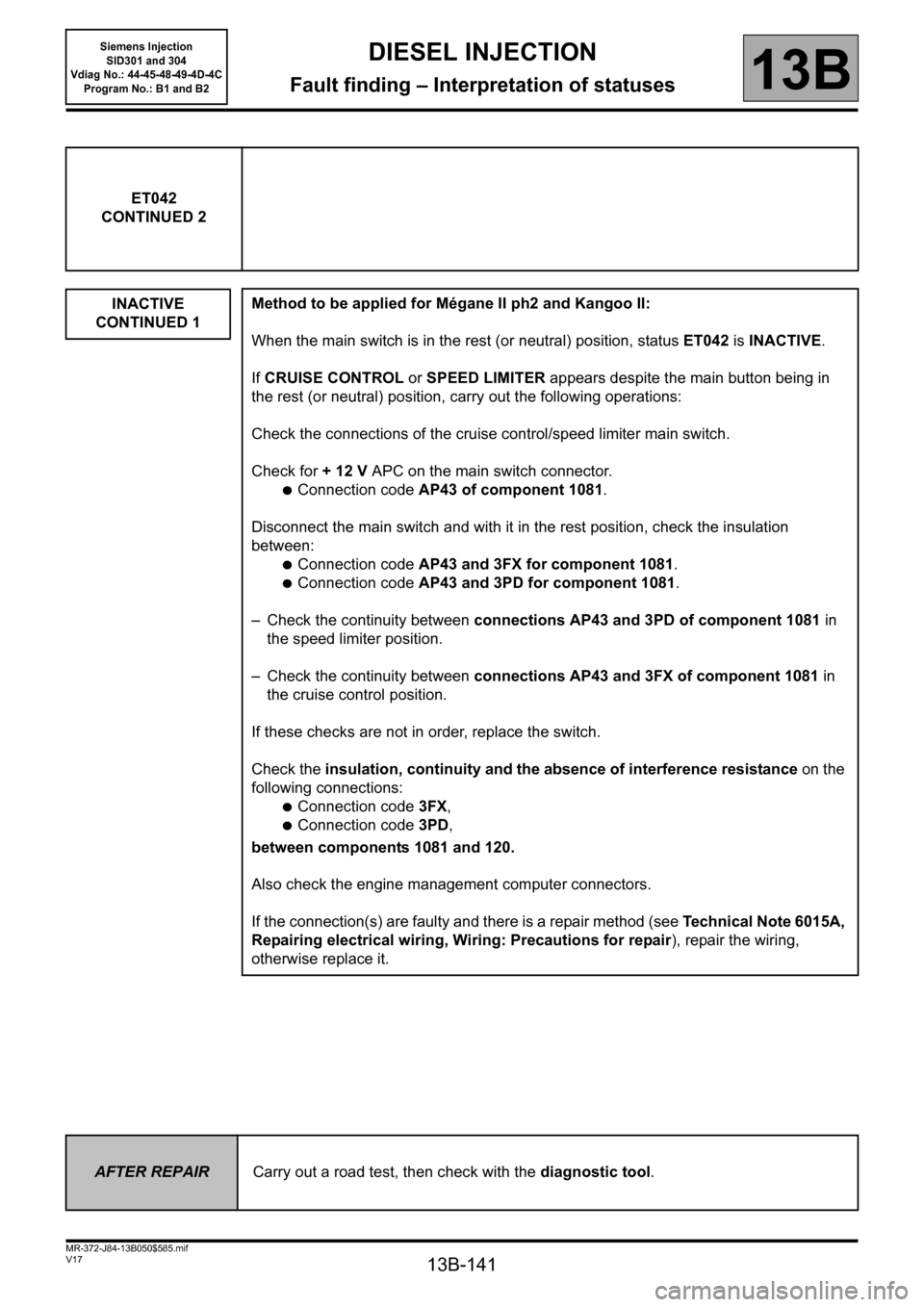
ET042
CONTINUED 2
INACTIVE
CONTINUED 1
Method to be applied for Mégane II ph2 and Kangoo II:
When the main switch is in the rest (or neutral) position, status ET042 is INACTIVE.
If CRUISE CONTROL or SPEED LIMITER appears despite the main button being in
the rest (or neutral) position, carry out the following operations:
Check the connections of the cruise control/speed limiter main switch.
Check for + 12 V APC on the main switch connector.
●Connection code AP43 of component 1081.
Disconnect the main switch and with it in the rest position, check the insulation
between:
●Connection code AP43 and 3FX for component 1081.
●Connection code AP43 and 3PD for component 1081.
– Check the continuity between connections AP43 and 3PD of component 1081 in
the speed limiter position.
– Check the continuity between connections AP43 and 3FX of component 1081 in
the cruise control position.
If these checks are not in order, replace the switch.
Check the insulation, continuity and the absence of interference resistance on the
following connections:
●Connection code 3FX,
●Connection code 3PD,
between components 1081 and 120.
Also check the engine management computer connectors.
If the connection(s) are faulty and there is a repair method (see Technical Note 6015A,
Repairing electrical wiring, Wiring: Precautions for repair), repair the wiring,
otherwise replace it.
AFTER REPAIRCarry out a road test, then check with the diagnostic tool.
Page 142 of 329
13B-142
MR-372-J84-13B050$585.mif
V17
Siemens Injection
SID301 and 304
Vdiag No.: 44-45-48-49-4D-4C
Program No.: B1 and B2DIESEL INJECTION
Fault finding – Interpretation of statuses13B
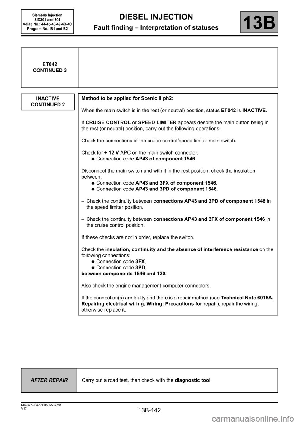
ET042
CONTINUED 3
INACTIVE
CONTINUED 2
Method to be applied for Scenic II ph2:
When the main switch is in the rest (or neutral) position, status ET042 is INACTIVE.
If CRUISE CONTROL or SPEED LIMITER appears despite the main button being in
the rest (or neutral) position, carry out the following operations:
Check the connections of the cruise control/speed limiter main switch.
Check for + 12 V APC on the main switch connector.
●Connection code AP43 of component 1546.
Disconnect the main switch and with it in the rest position, check the insulation
between:
●Connection code AP43 and 3FX of component 1546.
●Connection code AP43 and 3PD of component 1546.
– Check the continuity between connections AP43 and 3PD of component 1546 in
the speed limiter position.
– Check the continuity between connections AP43 and 3FX of component 1546 in
the cruise control position.
If these checks are not in order, replace the switch.
Check the insulation, continuity and the absence of interference resistance on the
following connections:
●Connection code 3FX,
●Connection code 3PD,
between components 1546 and 120.
Also check the engine management computer connectors.
If the connection(s) are faulty and there is a repair method (see Technical Note 6015A,
Repairing electrical wiring, Wiring: Precautions for repair), repair the wiring,
otherwise replace it.
AFTER REPAIRCarry out a road test, then check with the diagnostic tool.
Page 143 of 329
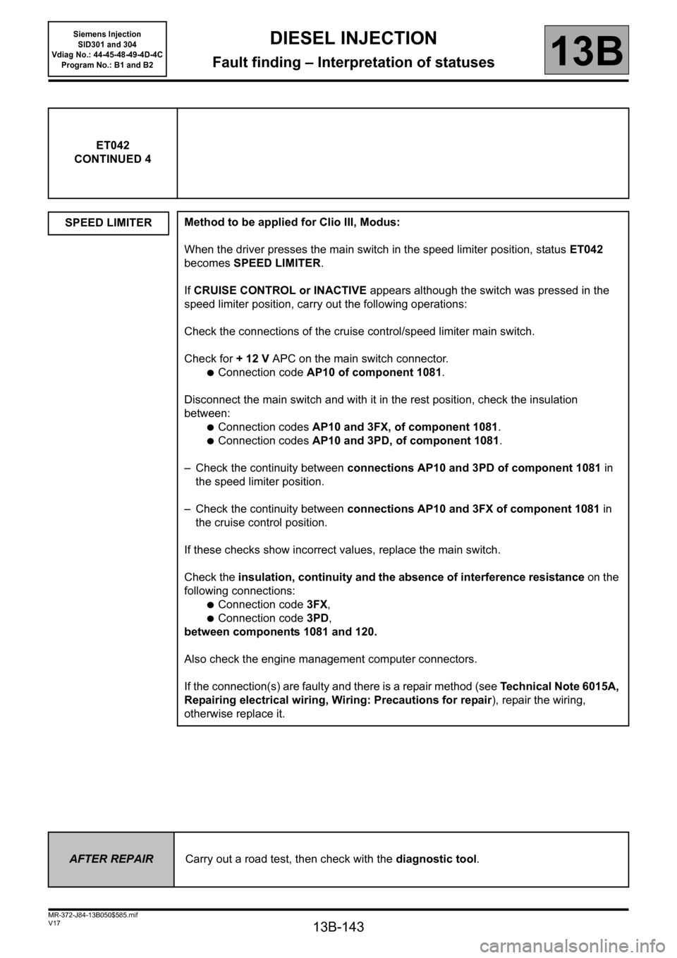
13B-143
MR-372-J84-13B050$585.mif
V17
Siemens Injection
SID301 and 304
Vdiag No.: 44-45-48-49-4D-4C
Program No.: B1 and B2DIESEL INJECTION
Fault finding – Interpretation of statuses13B
ET042
CONTINUED 4
SPEED LIMITER
Method to be applied for Clio III, Modus:
When the driver presses the main switch in the speed limiter position, status ET042
becomes SPEED LIMITER.
If CRUISE CONTROL or INACTIVE appears although the switch was pressed in the
speed limiter position, carry out the following operations:
Check the connections of the cruise control/speed limiter main switch.
Check for + 12 V APC on the main switch connector.
●Connection code AP10 of component 1081.
Disconnect the main switch and with it in the rest position, check the insulation
between:
●Connection codes AP10 and 3FX, of component 1081.
●Connection codes AP10 and 3PD, of component 1081.
– Check the continuity between connections AP10 and 3PD of component 1081 in
the speed limiter position.
– Check the continuity between connections AP10 and 3FX of component 1081 in
the cruise control position.
If these checks show incorrect values, replace the main switch.
Check the insulation, continuity and the absence of interference resistance on the
following connections:
●Connection code 3FX,
●Connection code 3PD,
between components 1081 and 120.
Also check the engine management computer connectors.
If the connection(s) are faulty and there is a repair method (see Technical Note 6015A,
Repairing electrical wiring, Wiring: Precautions for repair), repair the wiring,
otherwise replace it.
AFTER REPAIRCarry out a road test, then check with the diagnostic tool.