charging RENAULT SCENIC 2011 J95 / 3.G Engine And Peripherals Siemens Injection Workshop Manual
[x] Cancel search | Manufacturer: RENAULT, Model Year: 2011, Model line: SCENIC, Model: RENAULT SCENIC 2011 J95 / 3.GPages: 329, PDF Size: 1.71 MB
Page 10 of 329
13B-10
MR-372-J84-13B050$117.mif
V17
Siemens Injection
SID301 and 304
Vdiag No.: 44-45-48-49-4D-4C
Program No.: B1 and B2DIESEL INJECTION
Fault finding – List and location of components13B
Heating elements:
The heating elements are located in the cooling circuit before the additional coolant pump which cools the
turbocharger (Vdiag 45, 49 and 4D only).
Coolant temperature sensor:
The sensor is located on the cylinder head near the engine water chamber.
Air temperature sensor:
The air temperature sensor is located at the air circuit inlet, integrated into the air flowmeter.
Turbocharging pressure sensor solenoid valve:
The solenoid valve is located on the turbocharger.
Catalytic converter:
The catalytic converter is located upstream of the exhaust system and downstream of the turbocharger.
Fuel temperature sensor:
The sensor is located near the injection pump and injector return.
Catalytic converter downstream temperature sensor:
The sensor is located after the catalytic converter.
Turbine upstream temperature sensor:
This sensor is located between the exhaust pipe and the turbocharger.
Cruise control/speed limiter on/off switch:
This switch is located in the passenger compartment to the left of the steering wheel near the lighting dimmer.
Water in diesel fuel sensor (optional):
This sensor is located in the diesel filter.
Fan unit relay:
The relay is located on the cooling radiator.
Accelerator potentiometer:
The potentiometer is located on the accelerator pedal.
Brake pedal switch:
The switch is located on the brake pedal.
Clutch pedal switch:
The switch is located on the clutch pedal.
Heater plugs:
The heater plugs are located on the cylinder head.
Particle filter injector:
The injector is located between the particle filter injector fuel pump and the exhaust pipe. (Vdiag 45, 49 and 4D only)
Electric fuel pump:
The pump is located between the tank and the particle filter injector fuel filter. (Vdiag 45, 49 and 4D only)
Page 12 of 329
13B-12
MR-372-J84-13B050$156.mif
V17
13B
DIESEL INJECTION
Fault finding – Operating diagram
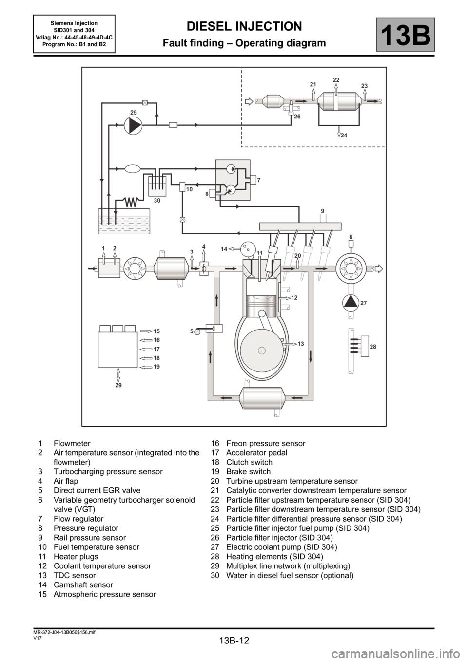
1 Flowmeter
2 Air temperature sensor (integrated into the
flowmeter)
3 Turbocharging pressure sensor
4 Air flap
5 Direct current EGR valve
6 Variable geometry turbocharger solenoid
valve (VGT)
7 Flow regulator
8 Pressure regulator
9 Rail pressure sensor
10 Fuel temperature sensor
11 Heater plugs
12 Coolant temperature sensor
13 TDC sensor
14 Camshaft sensor
15 Atmospheric pressure sensor16 Freon pressure sensor
17 Accelerator pedal
18 Clutch switch
19 Brake switch
20 Turbine upstream temperature sensor
21 Catalytic converter downstream temperature sensor
22 Particle filter upstream temperature sensor (SID 304)
23 Particle filter downstream temperature sensor (SID 304)
24 Particle filter differential pressure sensor (SID 304)
25 Particle filter injector fuel pump (SID 304)
26 Particle filter injector (SID 304)
27 Electric coolant pump (SID 304)
28 Heating elements (SID 304)
29 Multiplex line network (multiplexing)
30 Water in diesel fuel sensor (optional)
MR-372-J84-13B050$156.mif
Siemens Injection
SID301 and 304
Vdiag No.: 44-45-48-49-4D-4C
Program No.: B1 and B2
Page 15 of 329
13B-15
MR-372-J84-13B050$195.mif
V17
Siemens Injection
SID301 and 304
Vdiag No.: 44-45-48-49-4D-4C
Program No.: B1 and B2DIESEL INJECTION
Fault finding – Function13B
Engine synchronisation
One of the determining factors for fuel injection control is knowing the position of each of the pistons in their
respective cylinders at all times.
The angular position is measured using a TDC sensor triggered by machined teeth on the flywheel. The flywheel
has 60 teeth, with 2 teeth missing which forms a notch which is used as a reference point for the 1
st cylinder.
A second sensor (Hall-effect), excited by a machined tooth on the camshaft, and turning at half the engine speed,
provides information on the progress of the injection cycle. When the piston of cylinder 1 is at top dead centre (TDC),
either at the end of the compression stroke or at the end of the exhaust stroke, the camshaft sensor enables
a distinction to be made between these two states.
By comparing the signals from these two sensors, the computer is able to provide all of its systems with
synchronisation parameters, namely: the angular position of the flywheel, engine speed, the number of the active
injector and the progress of the injection cycle.
The module supplies the system with the rotation speed signal.
The camshaft sensor is only used when starting the engine. As soon as the engine is running by itself (not being
cranked by the starter), the signal provided by the TDC sensor is sufficient. A camshaft sensor fault, when the
engine is running, does not prevent the engine from operating correctly.
Quantity of fuel injected and control of start of injection
The parameters for controlling injection are, for each cylinder, the quantity to be injected and the start of injection.
These parameters are calculated by the injection computer using the following information:
– Engine speed.
– Accelerator pedal position.
– Turbocharging air pressure.
– Coolant temperature.
– Air temperature.
– Fuel temperature.
–Air flow.
– Pressure of fuel in the rail.
Page 17 of 329
13B-17
MR-372-J84-13B050$195.mif
V17
Siemens Injection
SID301 and 304
Vdiag No.: 44-45-48-49-4D-4C
Program No.: B1 and B2DIESEL INJECTION
Fault finding – Function13B
AIR SUPPLY
Measurement of the fresh air flow
The flow of fresh air entering the engine is measured by a flow sensor (ratiometric hot-wire sensor).
A fresh air temperature sensor is integrated into the air flowmeter.
EGR valve control
The EGR (exhaust gas recirculation) system consists of a direct current EGR valve fitted with a valve position
sensor. The EGR valve is controlled in a closed-loop via the position sensor. Up to a certain rate, exhaust gas
recirculation enables nitrogen oxide (NOx) emissions to be reduced significantly.
Turbocharger control
The turbocharger system consists of a solenoid valve connected to the vacuum pump circuit, which controls the
vanes via a diaphragm to create an overpressure or a vacuum in the fresh air inlet circuit (the overpressure can
reach 2.6 bar).
Damper valve control (for Vdiag 44, 45, 48, 49 and 4D only)
By default the valve is open when in the rest position and is actuated only when the engine is switched off; this has
a damping effect and helps to stop the engine.
It also controls the flow of fresh air during regeneration.
IDLE SPEED MANAGEMENT
The injection computer regulates the idle speed according to the idle speed setpoint which it calculates.
The idle speed setpoint is dependent on:
– the coolant temperature,
– the emission control programs,
– air conditioning requirements,
– the gear ratio engaged (automatic or sequential gearbox),
– the electrical consumers,
– battery voltage.
ENGINE TORQUE MANAGEMENT
The torque structure is the system which translates the driver's request into a torque supplied by the engine. Certain
functions such as the electronic stability program (ESP), the automatic gearbox (BVA) or the sequential gearbox
(BVR), if fitted to the vehicle, use this information.
Each inter-system (ESP, automatic gearbox, sequential gearbox) sends the injection computer a torque request via
the multiplex network.
The injection computer arbitrates between the inter-system torque requests and the driver request (depressing the
accelerator pedal or setting the cruise control/speed limiter function). The result of the arbitration gives the torque
setpoint.
From this torque set point, the computer determines the quantity of fuel to be injected (injection duration and number
of injection processes) and the amount of air required (turbocharging pressure and EGR valve rate) so that the
engine is able to provide the torque required in the best possible conditions (in terms of smooth running
performance, pollutant emissions, etc.).
Page 21 of 329
13B-21
MR-372-J84-13B050$195.mif
V17
Siemens Injection
SID301 and 304
Vdiag No.: 44-45-48-49-4D-4C
Program No.: B1 and B2DIESEL INJECTION
Fault finding – Function13B
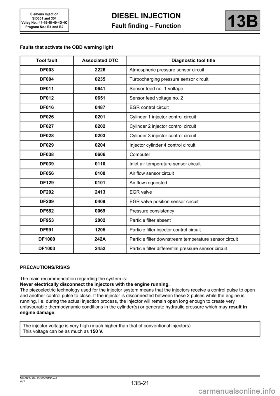
Faults that activate the OBD warning light
PRECAUTIONS/RISKS
The main recommendation regarding the system is:
Never electrically disconnect the injectors with the engine running.
The piezoelectric technology used for the injector system means that the injectors receive a control pulse to open
and another control pulse to close. If the injector is disconnected between these 2 pulses while the engine is
running, i.e. during the actual injection process, the injector will remain open long enough to create very
unfavourable thermodynamic conditions in the cylinder(s) or generate hydraulic pressure which may result in
engine damage. Tool fault Associated DTC Diagnostic tool title
DF003 2226Atmospheric pressure sensor circuit
DF004 0235Turbocharging pressure sensor circuit
DF011 0641Sensor feed no. 1 voltage
DF012 0651Sensor feed voltage no. 2
DF016 0487EGR control circuit
DF026 0201Cylinder 1 injector control circuit
DF027 0202Cylinder 2 injector control circuit
DF028 0203Cylinder 3 injector control circuit
DF029 0204Injector cylinder 4 control circuit
DF038 0606Computer
DF039 0110Inlet air temperature sensor circuit
DF056 0100Air flow sensor circuit
DF129 0101Air flow requested
DF202 2413EGR valve
DF209 0409EGR valve position sensor circuit
DF582 0069Pressure consistency
DF953 2002Particle filter absent
DF991 1205Particle filter injector control circuit
DF1000 242AParticle filter downstream temperature sensor circuit
DF1003 2452Particle filter differential pressure sensor circuit
The injector voltage is very high (much higher than that of conventional injectors)
This voltage can be as much as 150 V.
Page 22 of 329
13B-22
MR-372-J84-13B050$195.mif
V17
Siemens Injection
SID301 and 304
Vdiag No.: 44-45-48-49-4D-4C
Program No.: B1 and B2DIESEL INJECTION
Fault finding – Function13B
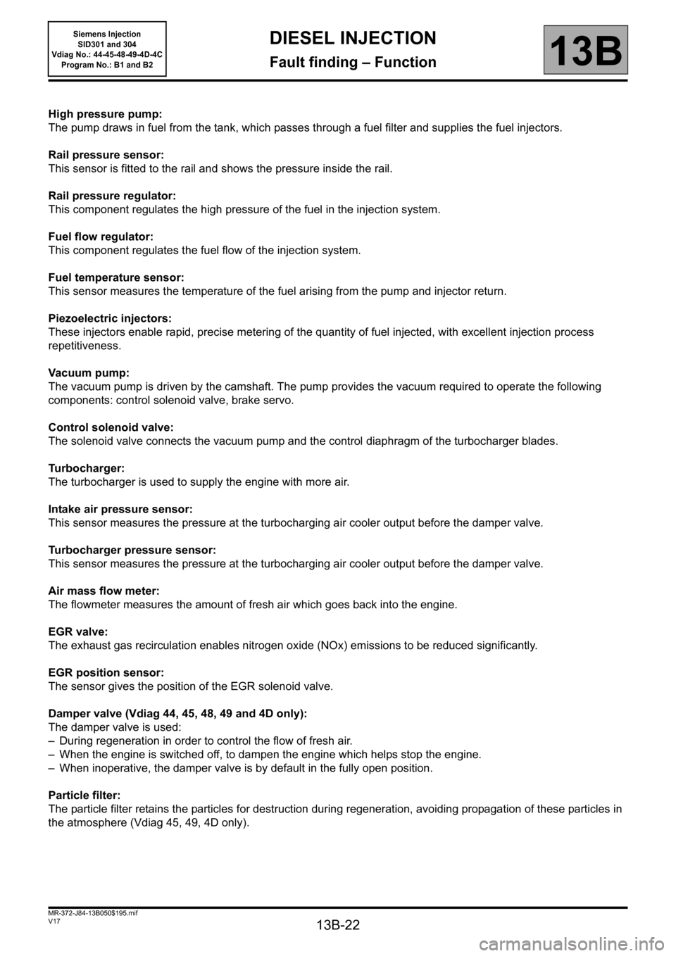
High pressure pump:
The pump draws in fuel from the tank, which passes through a fuel filter and supplies the fuel injectors.
Rail pressure sensor:
This sensor is fitted to the rail and shows the pressure inside the rail.
Rail pressure regulator:
This component regulates the high pressure of the fuel in the injection system.
Fuel flow regulator:
This component regulates the fuel flow of the injection system.
Fuel temperature sensor:
This sensor measures the temperature of the fuel arising from the pump and injector return.
Piezoelectric injectors:
These injectors enable rapid, precise metering of the quantity of fuel injected, with excellent injection process
repetitiveness.
Vacuum pump:
The vacuum pump is driven by the camshaft. The pump provides the vacuum required to operate the following
components: control solenoid valve, brake servo.
Control solenoid valve:
The solenoid valve connects the vacuum pump and the control diaphragm of the turbocharger blades.
Turbocharger:
The turbocharger is used to supply the engine with more air.
Intake air pressure sensor:
This sensor measures the pressure at the turbocharging air cooler output before the damper valve.
Turbocharger pressure sensor:
This sensor measures the pressure at the turbocharging air cooler output before the damper valve.
Air mass flow meter:
The flowmeter measures the amount of fresh air which goes back into the engine.
EGR valve:
The exhaust gas recirculation enables nitrogen oxide (NOx) emissions to be reduced significantly.
EGR position sensor:
The sensor gives the position of the EGR solenoid valve.
Damper valve (Vdiag 44, 45, 48, 49 and 4D only):
The damper valve is used:
– During regeneration in order to control the flow of fresh air.
– When the engine is switched off, to dampen the engine which helps stop the engine.
– When inoperative, the damper valve is by default in the fully open position.
Particle filter:
The particle filter retains the particles for destruction during regeneration, avoiding propagation of these particles in
the atmosphere (Vdiag 45, 49, 4D only).
Page 23 of 329
13B-23
MR-372-J84-13B050$195.mif
V17
Siemens Injection
SID301 and 304
Vdiag No.: 44-45-48-49-4D-4C
Program No.: B1 and B2DIESEL INJECTION
Fault finding – Function13B
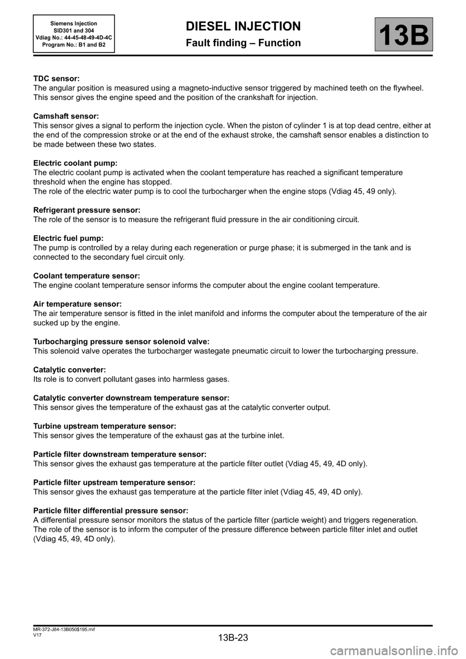
TDC sensor:
The angular position is measured using a magneto-inductive sensor triggered by machined teeth on the flywheel.
This sensor gives the engine speed and the position of the crankshaft for injection.
Camshaft sensor:
This sensor gives a signal to perform the injection cycle. When the piston of cylinder 1 is at top dead centre, either at
the end of the compression stroke or at the end of the exhaust stroke, the camshaft sensor enables a distinction to
be made between these two states.
Electric coolant pump:
The electric coolant pump is activated when the coolant temperature has reached a significant temperature
threshold when the engine has stopped.
The role of the electric water pump is to cool the turbocharger when the engine stops (Vdiag 45, 49 only).
Refrigerant pressure sensor:
The role of the sensor is to measure the refrigerant fluid pressure in the air conditioning circuit.
Electric fuel pump:
The pump is controlled by a relay during each regeneration or purge phase; it is submerged in the tank and is
connected to the secondary fuel circuit only.
Coolant temperature sensor:
The engine coolant temperature sensor informs the computer about the engine coolant temperature.
Air temperature sensor:
The air temperature sensor is fitted in the inlet manifold and informs the computer about the temperature of the air
sucked up by the engine.
Turbocharging pressure sensor solenoid valve:
This solenoid valve operates the turbocharger wastegate pneumatic circuit to lower the turbocharging pressure.
Catalytic converter:
Its role is to convert pollutant gases into harmless gases.
Catalytic converter downstream temperature sensor:
This sensor gives the temperature of the exhaust gas at the catalytic converter output.
Turbine upstream temperature sensor:
This sensor gives the temperature of the exhaust gas at the turbine inlet.
Particle filter downstream temperature sensor:
This sensor gives the exhaust gas temperature at the particle filter outlet (Vdiag 45, 49, 4D only).
Particle filter upstream temperature sensor:
This sensor gives the exhaust gas temperature at the particle filter inlet (Vdiag 45, 49, 4D only).
Particle filter differential pressure sensor:
A differential pressure sensor monitors the status of the particle filter (particle weight) and triggers regeneration.
The role of the sensor is to inform the computer of the pressure difference between particle filter inlet and outlet
(Vdiag 45, 49, 4D only).
Page 31 of 329
13B-31
MR-372-J84-13B050$351.mif
V17
13B
DIESEL INJECTION
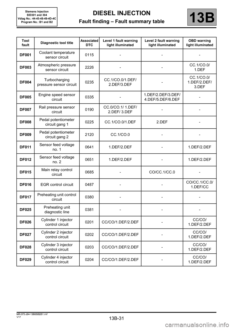
Fault finding – Fault summary table
Tool
faultDiagnostic tool titleAssociated
DTCLevel 1 fault warning
light illuminatedLevel 2 fault warning
light illuminatedOBD warning
light illuminated
DF001Coolant temperature
sensor circuit0115 - - -
DF003Atmospheric pressure
sensor circuit2226 - -CC.1/CO.0/
1.DEF
DF004Turbocharging
pressure sensor circuit0235CC.1/CO.0/1.DEF/
2.DEF/3.DEF-CC.1/CO.0/
1.DEF/2.DEF/
3.DEF
DF005Engine speed sensor
circuit0335 -1.DEF/2.DEF/3.DEF/
4.DEF/5.DEF/6.DEF-
DF007Rail pressure sensor
circuit0190CC.0/CO.1/ 1.DEF/
2.DEF/ 3.DEF--
DF008Pedal potentiometer
circuit gang 10225 CC.1/CO.0/1.DEF 2.DEF -
DF009Pedal potentiometer
circuit gang 22120 CC.1/CO.0 - -
DF011Sensor feed voltage
no. 10641 1.DEF/2.DEF - 1.DEF/2.DEF
DF012Sensor feed voltage
no. 20651 1.DEF/2.DEF - 1.DEF/2.DEF
DF015Main relay control
circuit0685 - CO/CC.1/CC.0 -
DF016EGR control circuit 0487 - -CO/CC.1/CC.0/
1.DEF/CC
DF017Preheating unit control
circuit0380 - - -
DF025Preheating unit
diagnostic line0381 - - -
DF026Cylinder 1 injector
control circuit0201 CC/CO/1.DEF/2.DEF -CC/CO/
1.DEF/2.DEF
DF027Cylinder 2 injector
control circuit0202 CC/CO/1.DEF/2.DEF -CC/CO/
1.DEF/2.DEF
DF028Cylinder 3 injector
control circuit0203 CC/CO/1.DEF/2.DEF -CC/CO/
1.DEF/2.DEF
DF029Cylinder 4 injector
control circuit0204 CC/CO/1.DEF/2.DEF -CC/CO/
1.DEF/2.DEF
MR-372-J84-13B050$351.mif
Siemens Injection
SID301 and 304
Vdiag No.: 44-45-48-49-4D-4C
Program No.: B1 and B2
Page 32 of 329
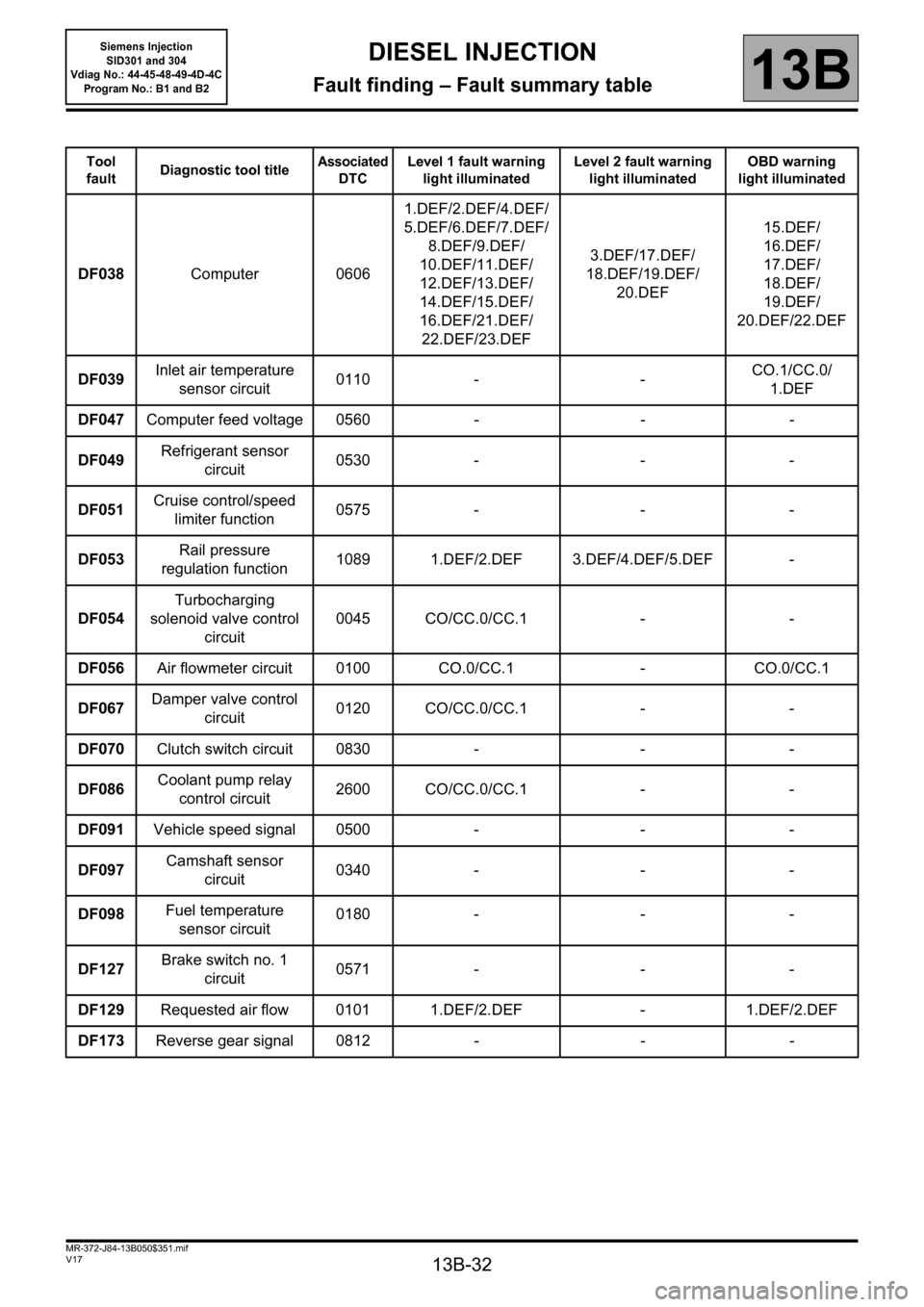
13B-32
MR-372-J84-13B050$351.mif
V17
Siemens Injection
SID301 and 304
Vdiag No.: 44-45-48-49-4D-4C
Program No.: B1 and B2DIESEL INJECTION
Fault finding – Fault summary table13B
Tool
faultDiagnostic tool titleAssociated
DTCLevel 1 fault warning
light illuminatedLevel 2 fault warning
light illuminatedOBD warning
light illuminated
DF038Computer 06061.DEF/2.DEF/4.DEF/
5.DEF/6.DEF/7.DEF/
8.DEF/9.DEF/
10.DEF/11.DEF/
12.DEF/13.DEF/
14.DEF/15.DEF/
16.DEF/21.DEF/
22.DEF/23.DEF3.DEF/17.DEF/
18.DEF/19.DEF/
20.DEF15.DEF/
16.DEF/
17.DEF/
18.DEF/
19.DEF/
20.DEF/22.DEF
DF039Inlet air temperature
sensor circuit0110 - -CO.1/CC.0/
1.DEF
DF047Computer feed voltage 0560 - - -
DF049Refrigerant sensor
circuit0530 - - -
DF051Cruise control/speed
limiter function0575 - - -
DF053Rail pressure
regulation function1089 1.DEF/2.DEF 3.DEF/4.DEF/5.DEF -
DF054Turbocharging
solenoid valve control
circuit0045 CO/CC.0/CC.1 - -
DF056Air flowmeter circuit 0100 CO.0/CC.1 - CO.0/CC.1
DF067Damper valve control
circuit0120 CO/CC.0/CC.1 - -
DF070Clutch switch circuit 0830 - - -
DF086Coolant pump relay
control circuit2600 CO/CC.0/CC.1 - -
DF091Vehicle speed signal 0500 - - -
DF097Camshaft sensor
circuit0340 - - -
DF098Fuel temperature
sensor circuit0180 - - -
DF127Brake switch no. 1
circuit0571 - - -
DF129Requested air flow 0101 1.DEF/2.DEF - 1.DEF/2.DEF
DF173Reverse gear signal 0812 - - -
Page 37 of 329
13B-37
MR-372-J84-13B050$390.mif
V17
DIESEL INJECTION
Fault finding – Interpretation of faults
Siemens Injection
SID301 and 304
Vdiag No. 44-45-48-49-4D-4C
Program No.: B1 and B2
13B
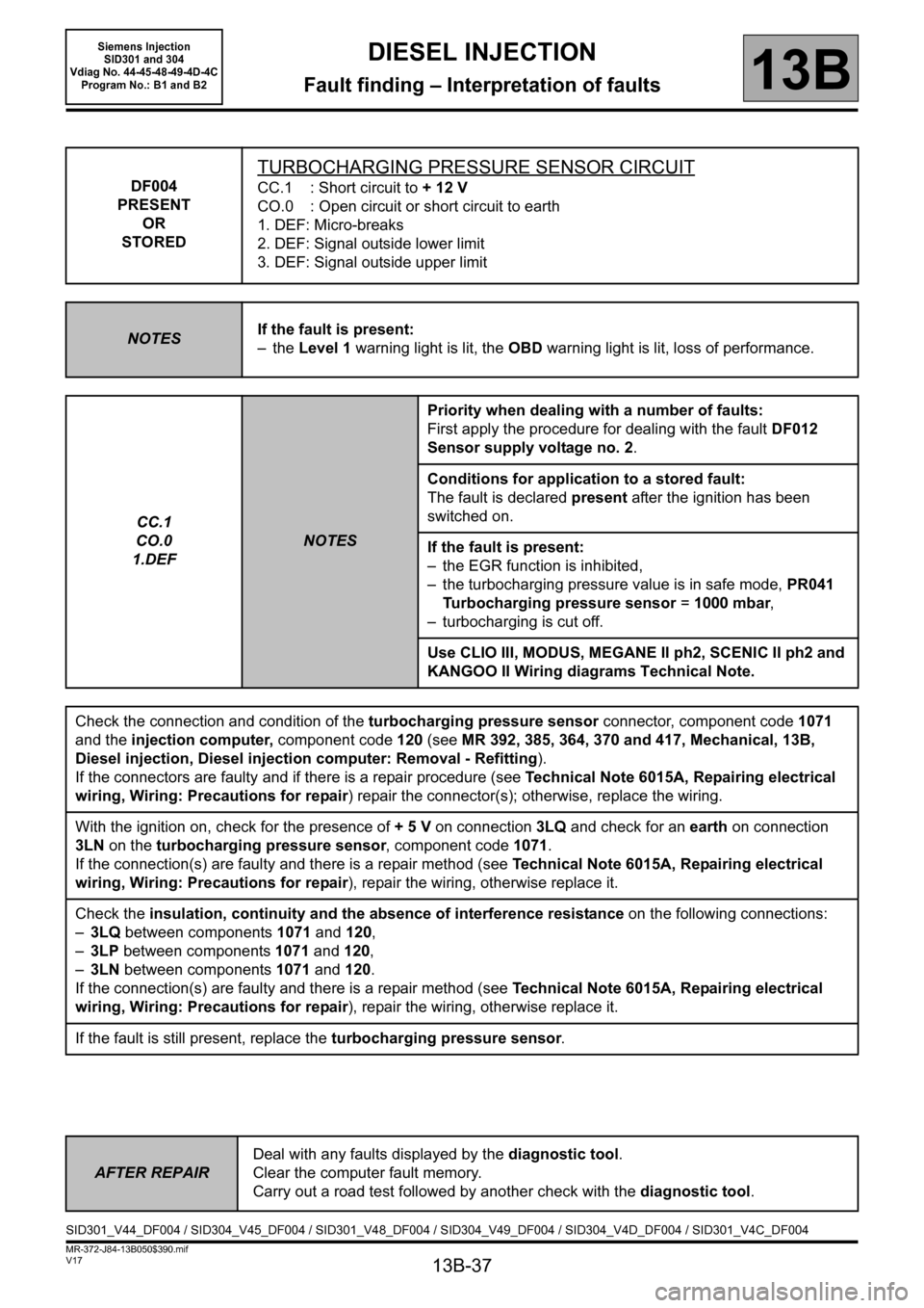
DF004
PRESENT
OR
STORED
TURBOCHARGING PRESSURE SENSOR CIRCUIT
CC.1 : Short circuit to + 12 V
CO.0 : Open circuit or short circuit to earth
1. DEF: Micro-breaks
2. DEF: Signal outside lower limit
3. DEF: Signal outside upper limit
NOTESIf the fault is present:
– the Level 1 warning light is lit, the OBD warning light is lit, loss of performance.
CC.1
CO.0
1.DEF
NOTESPriority when dealing with a number of faults:
First apply the procedure for dealing with the fault DF012
Sensor supply voltage no. 2.
Conditions for application to a stored fault:
The fault is declared present after the ignition has been
switched on.
If the fault is present:
– the EGR function is inhibited,
– the turbocharging pressure value is in safe mode, PR041
Turbocharging pressure sensor = 1000 mbar,
– turbocharging is cut off.
Use CLIO III, MODUS, MEGANE II ph2, SCENIC II ph2 and
KANGOO II Wiring diagrams Technical Note.
Check the connection and condition of the turbocharging pressure sensor connector, component code1071
and the injection computer, component code120 (see MR 392, 385, 364, 370 and 417, Mechanical, 13B,
Diesel injection, Diesel injection computer: Removal - Refitting).
If the connectors are faulty and if there is a repair procedure (see Technical Note 6015A, Repairing electrical
wiring, Wiring: Precautions for repair) repair the connector(s); otherwise, replace the wiring.
With the ignition on, check for the presence of + 5 V on connection 3LQ and check for an earth on connection
3LN on the turbocharging pressure sensor, component code 1071.
If the connection(s) are faulty and there is a repair method (see Technical Note 6015A, Repairing electrical
wiring, Wiring: Precautions for repair), repair the wiring, otherwise replace it.
Check the insulation, continuity and the absence of interference resistance on the following connections:
–3LQ between components 1071 and 120,
–3LP between components 1071 and 120,
–3LN between components 1071 and 120.
If the connection(s) are faulty and there is a repair method (see Technical Note 6015A, Repairing electrical
wiring, Wiring: Precautions for repair), repair the wiring, otherwise replace it.
If the fault is still present, replace the turbocharging pressure sensor.
AFTER REPAIRDeal with any faults displayed by the diagnostic tool.
Clear the computer fault memory.
Carry out a road test followed by another check with the diagnostic tool.
SID301_V44_DF004 / SID304_V45_DF004 / SID301_V48_DF004 / SID304_V49_DF004 / SID304_V4D_DF004 / SID301_V4C_DF004