charging RENAULT SCENIC 2011 J95 / 3.G Engine And Peripherals Siemens Injection User Guide
[x] Cancel search | Manufacturer: RENAULT, Model Year: 2011, Model line: SCENIC, Model: RENAULT SCENIC 2011 J95 / 3.GPages: 329, PDF Size: 1.71 MB
Page 38 of 329
13B-38
MR-372-J84-13B050$390.mif
V17
DIESEL INJECTION
Fault finding – Interpretation of faults
Siemens Injection
SID301 and 304
Vdiag No. 44-45-48-49-4D-4C
Program No.: B1 and B2
13B
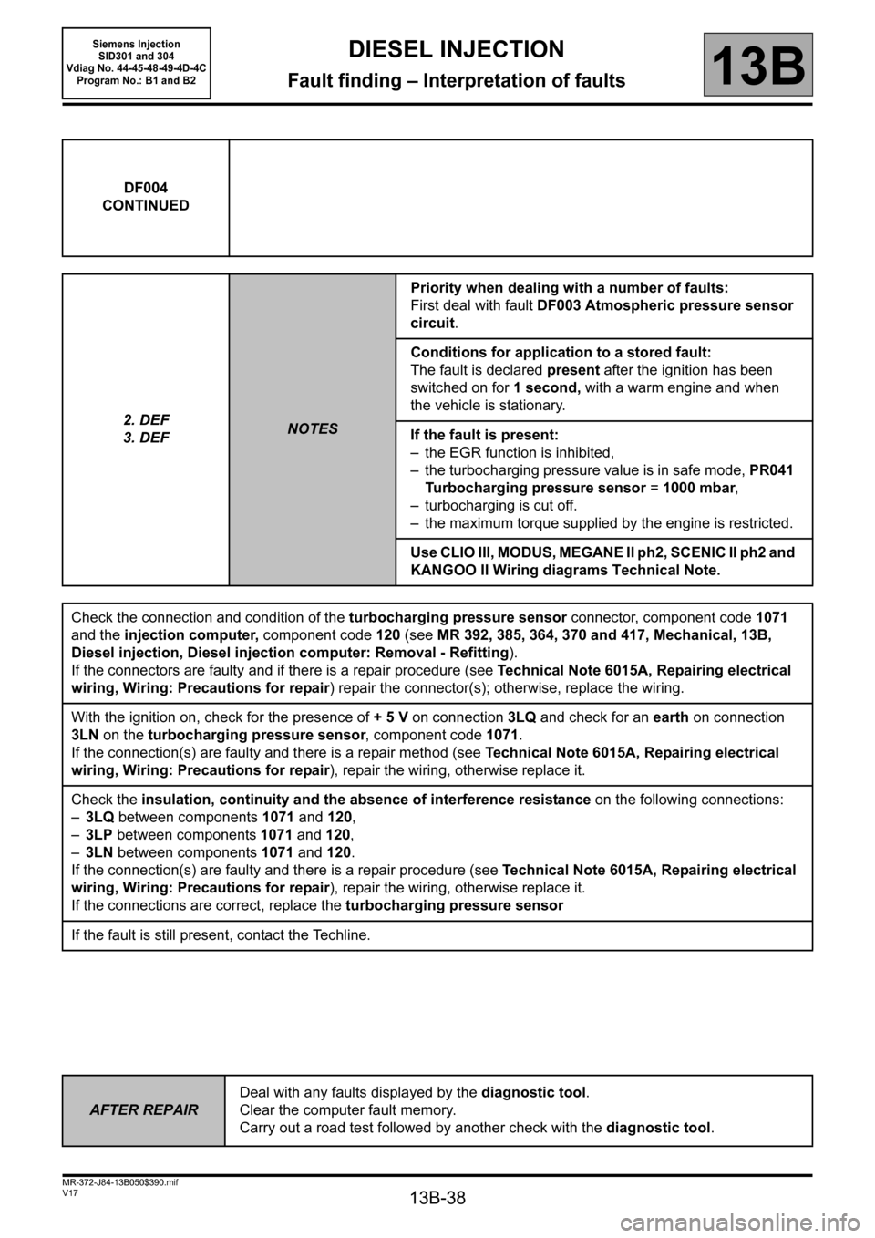
DF004
CONTINUED
2. DEF
3. DEF
NOTESPriority when dealing with a number of faults:
First deal with fault DF003 Atmospheric pressure sensor
circuit.
Conditions for application to a stored fault:
The fault is declared present after the ignition has been
switched on for 1 second, with a warm engine and when
the vehicle is stationary.
If the fault is present:
– the EGR function is inhibited,
– the turbocharging pressure value is in safe mode, PR041
Turbocharging pressure sensor = 1000 mbar,
– turbocharging is cut off.
– the maximum torque supplied by the engine is restricted.
Use CLIO III, MODUS, MEGANE II ph2, SCENIC II ph2 and
KANGOO II Wiring diagrams Technical Note.
Check the connection and condition of the turbocharging pressure sensor connector, component code1071
and the injection computer, component code120 (see MR 392, 385, 364, 370 and 417, Mechanical, 13B,
Diesel injection, Diesel injection computer: Removal - Refitting).
If the connectors are faulty and if there is a repair procedure (see Technical Note 6015A, Repairing electrical
wiring, Wiring: Precautions for repair) repair the connector(s); otherwise, replace the wiring.
With the ignition on, check for the presence of + 5 V on connection 3LQ and check for an earth on connection
3LN on the turbocharging pressure sensor, component code 1071.
If the connection(s) are faulty and there is a repair method (see Technical Note 6015A, Repairing electrical
wiring, Wiring: Precautions for repair), repair the wiring, otherwise replace it.
Check the insulation, continuity and the absence of interference resistance on the following connections:
–3LQ between components 1071 and 120,
–3LP between components 1071 and 120,
–3LN between components 1071 and 120.
If the connection(s) are faulty and there is a repair procedure (see Technical Note 6015A, Repairing electrical
wiring, Wiring: Precautions for repair), repair the wiring, otherwise replace it.
If the connections are correct, replace the turbocharging pressure sensor
If the fault is still present, contact the Techline.
AFTER REPAIRDeal with any faults displayed by the diagnostic tool.
Clear the computer fault memory.
Carry out a road test followed by another check with the diagnostic tool.
Page 46 of 329
13B-46
MR-372-J84-13B050$390.mif
V17
DIESEL INJECTION
Fault finding – Interpretation of faults
Siemens Injection
SID301 and 304
Vdiag No. 44-45-48-49-4D-4C
Program No.: B1 and B2
13B
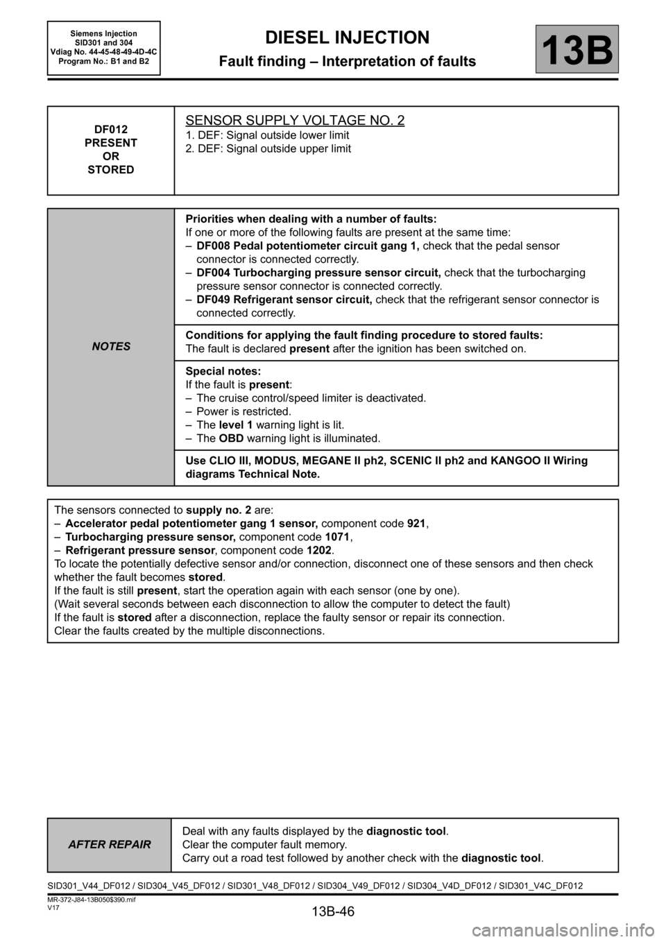
DF012
PRESENT
OR
STOREDSENSOR SUPPLY VOLTAGE NO. 2
1. DEF: Signal outside lower limit
2. DEF: Signal outside upper limit
NOTESPriorities when dealing with a number of faults:
If one or more of the following faults are present at the same time:
–DF008 Pedal potentiometer circuit gang 1, check that the pedal sensor
connector is connected correctly.
–DF004 Turbocharging pressure sensor circuit, check that the turbocharging
pressure sensor connector is connected correctly.
–DF049 Refrigerant sensor circuit, check that the refrigerant sensor connector is
connected correctly.
Conditions for applying the fault finding procedure to stored faults:
The fault is declared present after the ignition has been switched on.
Special notes:
If the fault is present:
– The cruise control/speed limiter is deactivated.
– Power is restricted.
–The level 1 warning light is lit.
–The OBD warning light is illuminated.
Use CLIO III, MODUS, MEGANE II ph2, SCENIC II ph2 and KANGOO II Wiring
diagrams Technical Note.
The sensors connected to supply no. 2 are:
–Accelerator pedal potentiometer gang 1 sensor, component code 921,
–Turbocharging pressure sensor, component code 1071,
–Refrigerant pressure sensor, component code 1202.
To locate the potentially defective sensor and/or connection, disconnect one of these sensors and then check
whether the fault becomes stored.
If the fault is still present, start the operation again with each sensor (one by one).
(Wait several seconds between each disconnection to allow the computer to detect the fault)
If the fault is stored after a disconnection, replace the faulty sensor or repair its connection.
Clear the faults created by the multiple disconnections.
AFTER REPAIRDeal with any faults displayed by the diagnostic tool.
Clear the computer fault memory.
Carry out a road test followed by another check with the diagnostic tool.
SID301_V44_DF012 / SID304_V45_DF012 / SID301_V48_DF012 / SID304_V49_DF012 / SID304_V4D_DF012 / SID301_V4C_DF012
Page 48 of 329
13B-48
MR-372-J84-13B050$390.mif
V17
DIESEL INJECTION
Fault finding – Interpretation of faults
Siemens Injection
SID301 and 304
Vdiag No. 44-45-48-49-4D-4C
Program No.: B1 and B2
13B
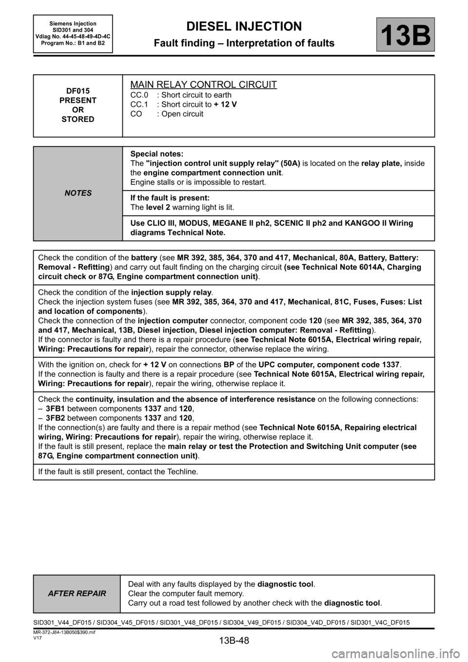
DF015
PRESENT
OR
STOREDMAIN RELAY CONTROL CIRCUIT
CC.0 : Short circuit to earth
CC.1 : Short circuit to + 12 V
CO : Open circuit
NOTESSpecial notes:
The "injection control unit supply relay" (50A) is located on the relay plate, inside
the engine compartment connection unit.
Engine stalls or is impossible to restart.
If the fault is present:
The level 2 warning light is lit.
Use CLIO III, MODUS, MEGANE II ph2, SCENIC II ph2 and KANGOO II Wiring
diagrams Technical Note.
Check the condition of the battery (see MR 392, 385, 364, 370 and 417, Mechanical, 80A, Battery, Battery:
Removal - Refitting) and carry out fault finding on the charging circuit (see Technical Note 6014A, Charging
circuit check or 87G, Engine compartment connection unit).
Check the condition of the injection supply relay.
Check the injection system fuses (see MR 392, 385, 364, 370 and 417, Mechanical, 81C, Fuses, Fuses: List
and location of components).
Check the connection of the injection computer connector, component code120 (see MR 392, 385, 364, 370
and 417, Mechanical, 13B, Diesel injection, Diesel injection computer: Removal - Refitting).
If the connector is faulty and there is a repair procedure (see Technical Note 6015A, Electrical wiring repair,
Wiring: Precautions for repair), repair the connector, otherwise replace the wiring.
With the ignition on, check for + 12 V on connections BP of the UPC computer, component code 1337.
If the connection is faulty and there is a repair procedure (see Technical Note 6015A, Electrical wiring repair,
Wiring: Precautions for repair), repair the wiring, otherwise replace it.
Check the continuity, insulation and the absence of interference resistance on the following connections:
–3FB1 between components 1337 and 120,
–3FB2 between components 1337 and 120,
If the connection(s) are faulty and there is a repair method (see Technical Note 6015A, Repairing electrical
wiring, Wiring: Precautions for repair), repair the wiring, otherwise replace it.
If the fault is still present, replace the main relay or test the Protection and Switching Unit computer (see
87G, Engine compartment connection unit).
If the fault is still present, contact the Techline.
AFTER REPAIRDeal with any faults displayed by the diagnostic tool.
Clear the computer fault memory.
Carry out a road test followed by another check with the diagnostic tool.
SID301_V44_DF015 / SID304_V45_DF015 / SID301_V48_DF015 / SID304_V49_DF015 / SID304_V4D_DF015 / SID301_V4C_DF015
Page 59 of 329
13B-59
MR-372-J84-13B050$390.mif
V17
DIESEL INJECTION
Fault finding – Interpretation of faults
Siemens Injection
SID301 and 304
Vdiag No. 44-45-48-49-4D-4C
Program No.: B1 and B2
13B
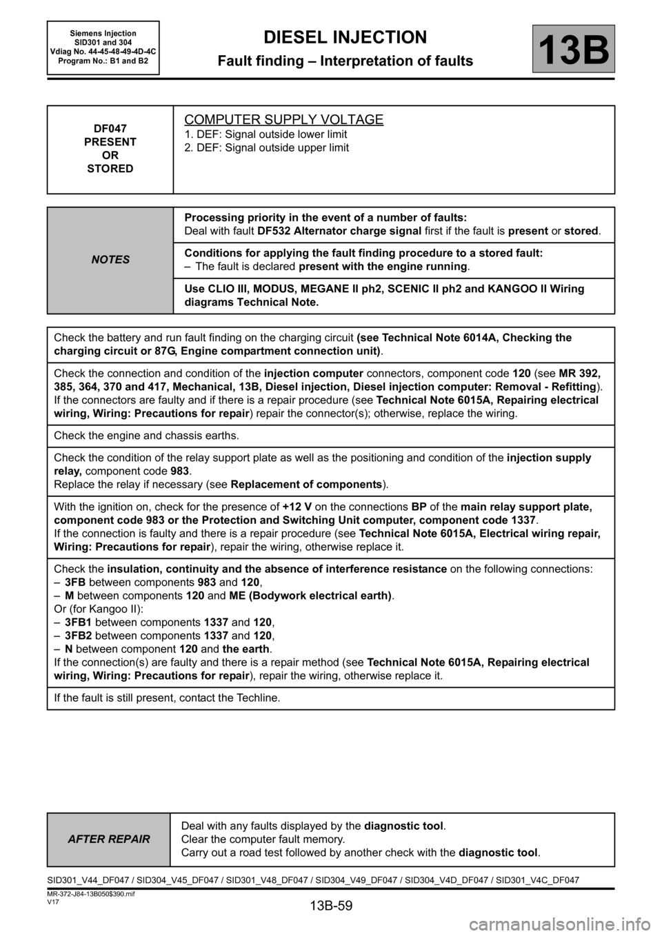
DF047
PRESENT
OR
STOREDCOMPUTER SUPPLY VOLTAGE
1. DEF: Signal outside lower limit
2. DEF: Signal outside upper limit
NOTESProcessing priority in the event of a number of faults:
Deal with fault DF532 Alternator charge signal first if the fault is present or stored.
Conditions for applying the fault finding procedure to a stored fault:
– The fault is declared present with the engine running.
Use CLIO III, MODUS, MEGANE II ph2, SCENIC II ph2 and KANGOO II Wiring
diagrams Technical Note.
Check the battery and run fault finding on the charging circuit (see Technical Note 6014A, Checking the
charging circuit or 87G, Engine compartment connection unit).
Check the connection and condition of the injection computer connectors, component code 120 (see MR 392,
385, 364, 370 and 417, Mechanical, 13B, Diesel injection, Diesel injection computer: Removal - Refitting).
If the connectors are faulty and if there is a repair procedure (see Technical Note 6015A, Repairing electrical
wiring, Wiring: Precautions for repair) repair the connector(s); otherwise, replace the wiring.
Check the engine and chassis earths.
Check the condition of the relay support plate as well as the positioning and condition of the injection supply
relay, component code 983.
Replace the relay if necessary (see Replacement of components).
With the ignition on, check for the presence of +12 V on the connectionsBP of the main relay support plate,
component code 983 or the Protection and Switching Unit computer, component code 1337.
If the connection is faulty and there is a repair procedure (see Technical Note 6015A, Electrical wiring repair,
Wiring: Precautions for repair), repair the wiring, otherwise replace it.
Check the insulation, continuity and the absence of interference resistance on the following connections:
–3FB between components983 and 120,
–M between components120 and ME (Bodywork electrical earth).
Or (for Kangoo II):
–3FB1 between components 1337 and 120,
–3FB2 between components 1337 and 120,
–N between component 120 and the earth.
If the connection(s) are faulty and there is a repair method (see Technical Note 6015A, Repairing electrical
wiring, Wiring: Precautions for repair), repair the wiring, otherwise replace it.
If the fault is still present, contact the Techline.
AFTER REPAIRDeal with any faults displayed by the diagnostic tool.
Clear the computer fault memory.
Carry out a road test followed by another check with the diagnostic tool.
SID301_V44_DF047 / SID304_V45_DF047 / SID301_V48_DF047 / SID304_V49_DF047 / SID304_V4D_DF047 / SID301_V4C_DF047
Page 63 of 329
13B-63
MR-372-J84-13B050$390.mif
V17
DIESEL INJECTION
Fault finding – Interpretation of faults
Siemens Injection
SID301 and 304
Vdiag No. 44-45-48-49-4D-4C
Program No.: B1 and B2
13B
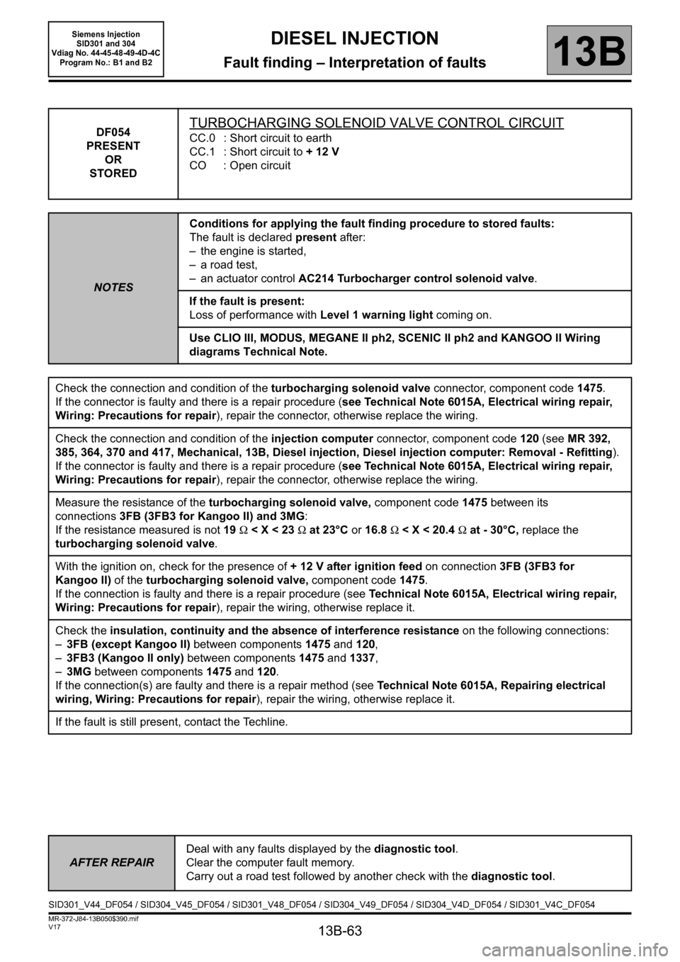
DF054
PRESENT
OR
STOREDTURBOCHARGING SOLENOID VALVE CONTROL CIRCUIT
CC.0 : Short circuit to earth
CC.1 : Short circuit to + 12 V
CO : Open circuit
NOTESConditions for applying the fault finding procedure to stored faults:
The fault is declared present after:
– the engine is started,
– a road test,
– an actuator control AC214 Turbocharger control solenoid valve.
If the fault is present:
Loss of performance with Level 1 warning light coming on.
Use CLIO III, MODUS, MEGANE II ph2, SCENIC II ph2 and KANGOO II Wiring
diagrams Technical Note.
Check the connection and condition of the turbocharging solenoid valve connector, component code1475.
If the connector is faulty and there is a repair procedure (see Technical Note 6015A, Electrical wiring repair,
Wiring: Precautions for repair), repair the connector, otherwise replace the wiring.
Check the connection and condition of the injection computer connector, component code 120 (see MR 392,
385, 364, 370 and 417, Mechanical, 13B, Diesel injection, Diesel injection computer: Removal - Refitting).
If the connector is faulty and there is a repair procedure (see Technical Note 6015A, Electrical wiring repair,
Wiring: Precautions for repair), repair the connector, otherwise replace the wiring.
Measure the resistance of the turbocharging solenoid valve, component code1475 between its
connections3FB (3FB3 for Kangoo II) and 3MG:
If the resistance measured is not 19Ω
With the ignition on, check for the presence of + 12 V after ignition feed on connection3FB (3FB3 for
Kangoo II) of the turbocharging solenoid valve, component code1475.
If the connection is faulty and there is a repair procedure (see Technical Note 6015A, Electrical wiring repair,
Wiring: Precautions for repair), repair the wiring, otherwise replace it.
Check the insulation, continuity and the absence of interference resistance on the following connections:
–3FB (except Kangoo II) between components 1475 and 120,
–3FB3 (Kangoo II only) between components 1475 and
1337,
–3MG between components1475 and 120.
If the connection(s) are faulty and there is a repair method (see Technical Note 6015A, Repairing electrical
wiring, Wiring: Precautions for repair), repair the wiring, otherwise replace it.
If the fault is still present, contact the Techline.
AFTER REPAIRDeal with any faults displayed by the diagnostic tool.
Clear the computer fault memory.
Carry out a road test followed by another check with the diagnostic tool.
SID301_V44_DF054 / SID304_V45_DF054 / SID301_V48_DF054 / SID304_V49_DF054 / SID304_V4D_DF054 / SID301_V4C_DF054
Page 84 of 329

13B-84
MR-372-J84-13B050$429.mif
V17
DIESEL INJECTION
Fault finding – Interpretation of faults
Siemens Injection
SID301 and 304
Vdiag No.: 44-45-48-49-4D-4C
Program No.: B1 and B2
13B
DF301
PRESENT
OR
STOREDAIR INLET CIRCUIT
1. DEF: Signal outside lower limit
2. DEF: Signal outside upper limit
NOTESConditions for applying the fault finding procedure to a stored fault:
The fault becomes present after starting the engine.
If the fault is present:
–The level 1 fault warning light is lit on the instrument panel.
– Loss of performance.
– EGR cut off.
– Turbocharging cut-off.
Use CLIO III, MODUS, MEGANE II ph2, SCENIC II ph2 and KANGOO II Wiring
diagrams Technical Note.
Carry out Te s t 1 0: Air Chain at the level of the turbocharger.
Carry out Te s t 11: Turbocharger control solenoid valve.
Carry out Test 12: Turbocharger.
Check the connection and condition of the turbocharging solenoid valve connector, component code 1475 and
the connector for the injection computer, component code 120.
If the connectors are faulty and there is a repair procedure (see Technical Note 6015A, Electrical wiring repair,
Wiring: Precautions for repair), repair the connector, otherwise replace the wiring.
With the ignition on, check for + 12 V after ignition feed on connection 3MG of the turbocharging solenoid valve,
component code 1475.
Check for + after ignition supply on connection 3FB1 (or 3FB3 for Kangoo II) of the turbocharging control
solenoid valve.
If the connection is faulty and there is a repair procedure (see Technical Note 6015A, Electrical wiring repair,
Wiring: Precautions for repair), repair the wiring, otherwise replace it.
Check the insulation, continuity and the absence of interference resistance of the following connection:
–3MG between components1475 and 120.
If the connection is faulty and there is a repair procedure (see Technical Note 6015A, Electrical wiring repair,
Wiring: Precautions for repair), repair the wiring, otherwise replace it.
If the fault is still present, contact the Techline.
AFTER REPAIRDeal with any faults displayed by the diagnostic tool.
Clear the computer fault memory.
Carry out a road test followed by another check with the diagnostic tool.
SID301_V44_DF301 / SID304_V45_DF301 / SID301_V48_DF301 / SID304_V49_DF301 / SID304_V4D_DF301 / SID301_V4C_DF301
Page 88 of 329
13B-88
MR-372-J84-13B050$429.mif
V17
DIESEL INJECTION
Fault finding – Interpretation of faults
Siemens Injection
SID301 and 304
Vdiag No.: 44-45-48-49-4D-4C
Program No.: B1 and B2
13B
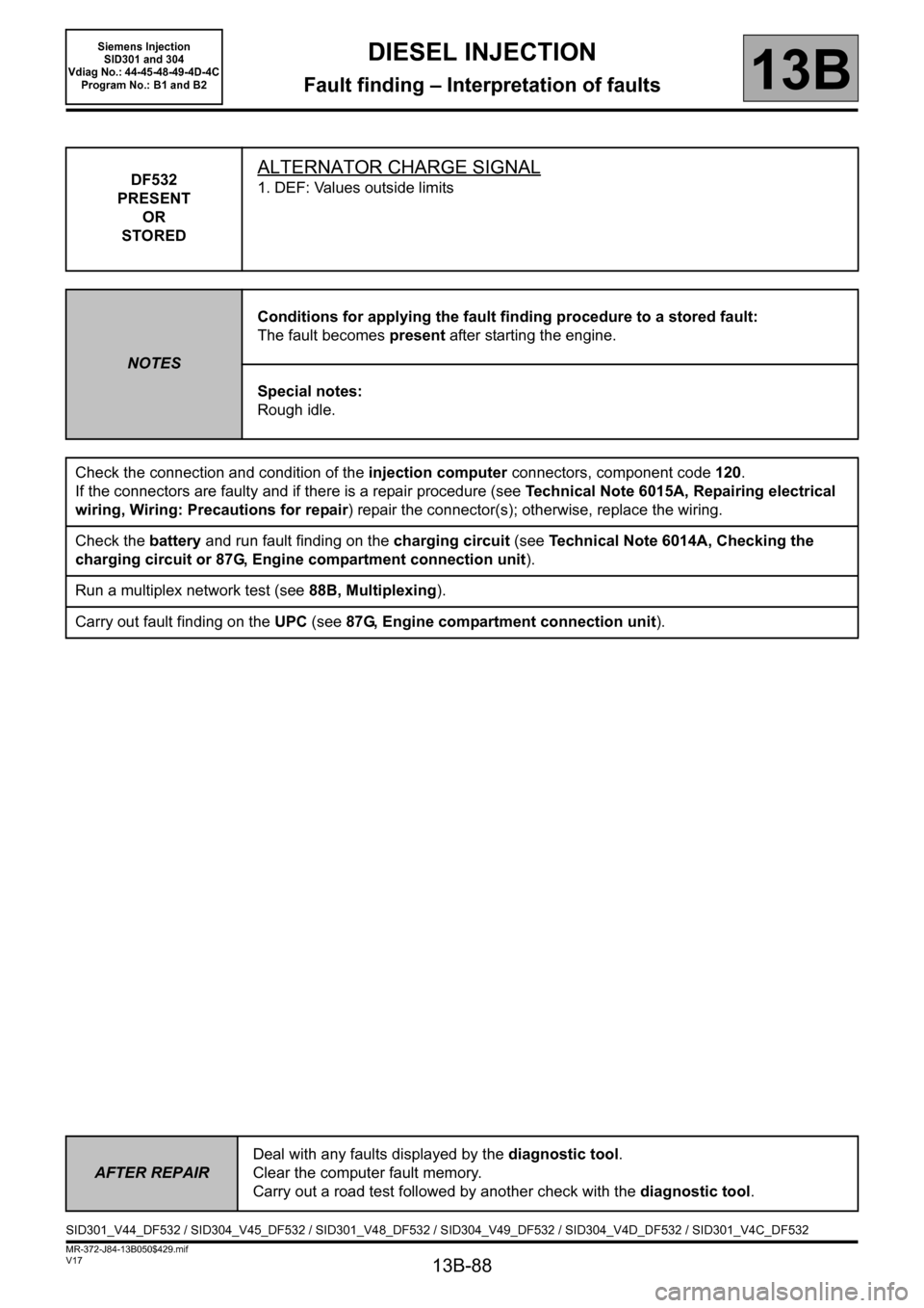
DF532
PRESENT
OR
STOREDALTERNATOR CHARGE SIGNAL
1. DEF: Values outside limits
NOTESConditions for applying the fault finding procedure to a stored fault:
The fault becomes present after starting the engine.
Special notes:
Rough idle.
Check the connection and condition of the injection computer connectors, component code 120.
If the connectors are faulty and if there is a repair procedure (see Technical Note 6015A, Repairing electrical
wiring, Wiring: Precautions for repair) repair the connector(s); otherwise, replace the wiring.
Check the battery and run fault finding on the charging circuit (see Technical Note 6014A, Checking the
charging circuit or 87G, Engine compartment connection unit).
Run a multiplex network test (see88B, Multiplexing).
Carry out fault finding on the UPC (see 87G, Engine compartment connection unit).
AFTER REPAIRDeal with any faults displayed by the diagnostic tool.
Clear the computer fault memory.
Carry out a road test followed by another check with the diagnostic tool.
SID301_V44_DF532 / SID304_V45_DF532 / SID301_V48_DF532 / SID304_V49_DF532 / SID304_V4D_DF532 / SID301_V4C_DF532
Page 89 of 329

13B-89
MR-372-J84-13B050$429.mif
V17
DIESEL INJECTION
Fault finding – Interpretation of faults
Siemens Injection
SID301 and 304
Vdiag No.: 44-45-48-49-4D-4C
Program No.: B1 and B2
13B
DF582
PRESENT
OR
STOREDPRESSURE CONSISTENCY
1. DEF: Signal outside lower limit
2. DEF: Signal outside upper limit
NOTESConditions for applying the fault finding procedure to a stored fault:
The fault becomes present after starting the engine.
If the fault is present:
–The level 1 and OBD fault warning lights are lit on the instrument panel.
–The cruise control/speed limiter is inhibited.
– Loss of performance, torque setpoint restricted.
Use CLIO III, MODUS, MEGANE II ph2, SCENIC II ph2 and KANGOO II Wiring
diagrams Technical Note.
Check the condition and connection of the turbocharging pressure sensor connector, component code 1071.
If the connector is faulty and there is a repair procedure (see Technical Note 6015A, Electrical wiring repair,
Wiring: Precautions for repair), repair the connector, otherwise replace the wiring.
Check the connection and condition of the injection computer connector, component code 120 (see MR 392,
385, 364, 370 and 417, Mechanical, 13B, Diesel injection, Diesel injection computer: Removal - Refitting).
If the connector is faulty and there is a repair procedure (see Technical Note 6015A, Electrical wiring repair,
Wiring: Precautions for repair), repair the connector, otherwise replace the wiring.
With the ignition on, check for + 5 V on connection 3LQ and earth on connection 3LN of the turbocharging
pressure sensor.
If the connection(s) are faulty and there is a repair method (see Technical Note 6015A, Repairing electrical
wiring, Wiring: Precautions for repair), repair the wiring, otherwise replace it.
Check the insulation, continuity and the absence of interference resistance on the following connections:
–3LQ between components 1071 and 120,
–3LN between components 1071 and 120,
–3LP between components 1071 and 120.
If the connection(s) are faulty and there is a repair method (see Technical Note 6015A, Repairing electrical
wiring, Wiring: Precautions for repair), repair the wiring, otherwise replace it.
Check the consistency between the atmospheric pressure and the turbocharging pressure (PR035
Atmospheric pressure = PR041 Turbocharging pressure
).
Engine stopped (cold), the pressure read by the two sensors must be nearly the same.
If the values are very different, replace the turbocharging pressure sensor.
If the fault is still present, contact the Techline.
AFTER REPAIRDeal with any faults displayed by the diagnostic tool.
Clear the computer fault memory.
Carry out a road test followed by another check with the diagnostic tool.
SID301_V44_DF582 / SID304_V45_DF582 / SID301_V48_DF582 / SID304_V49_DF582 / SID304_V4D_DF582 / SID301_V4C_DF582
Page 186 of 329
13B-186
MR-372-J84-13B050$663.mif
V17
13B
DIESEL INJECTION
Fault finding – Parameter summary table
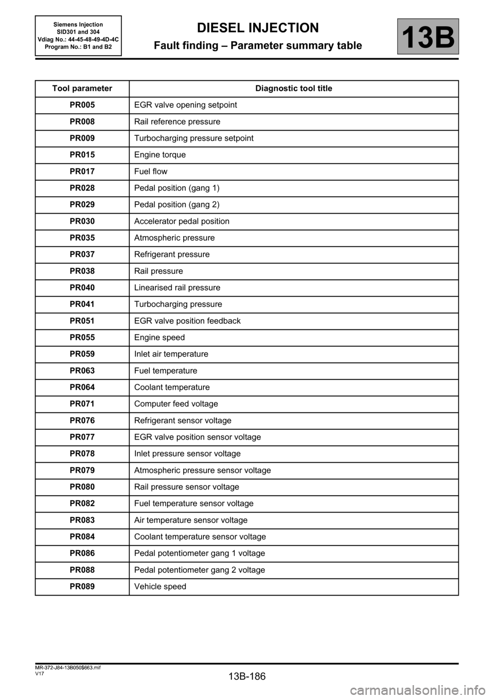
Tool parameter Diagnostic tool title
PR005EGR valve opening setpoint
PR008Rail reference pressure
PR009Turbocharging pressure setpoint
PR015Engine torque
PR017Fuel flow
PR028Pedal position (gang 1)
PR029Pedal position (gang 2)
PR030Accelerator pedal position
PR035Atmospheric pressure
PR037Refrigerant pressure
PR038Rail pressure
PR040Linearised rail pressure
PR041Turbocharging pressure
PR051EGR valve position feedback
PR055Engine speed
PR059Inlet air temperature
PR063Fuel temperature
PR064Coolant temperature
PR071Computer feed voltage
PR076Refrigerant sensor voltage
PR077EGR valve position sensor voltage
PR078Inlet pressure sensor voltage
PR079Atmospheric pressure sensor voltage
PR080Rail pressure sensor voltage
PR082Fuel temperature sensor voltage
PR083Air temperature sensor voltage
PR084Coolant temperature sensor voltage
PR086Pedal potentiometer gang 1 voltage
PR088Pedal potentiometer gang 2 voltage
PR089Vehicle speed
MR-372-J84-13B050$663.mif
Siemens Injection
SID301 and 304
Vdiag No.: 44-45-48-49-4D-4C
Program No.: B1 and B2
Page 187 of 329
13B-187
MR-372-J84-13B050$663.mif
V17
Siemens Injection
SID301 and 304
Vdiag No.: 44-45-48-49-4D-4C
Program No.: B1 and B2DIESEL INJECTION
Fault finding – Parameter summary table13B
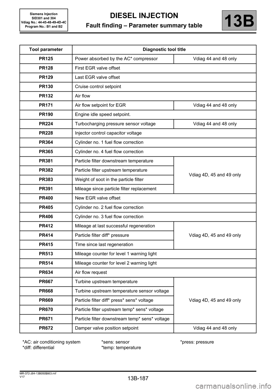
Tool parameter Diagnostic tool title
PR125Power absorbed by the AC* compressor Vdiag 44 and 48 only
PR128First EGR valve offset
PR129Last EGR valve offset
PR130Cruise control setpoint
PR132Air flow
PR171Air flow setpoint for EGR Vdiag 44 and 48 only
PR190Engine idle speed setpoint.
PR224Turbocharging pressure sensor voltage Vdiag 44 and 48 only
PR228Injector control capacitor voltage
PR364Cylinder no. 1 fuel flow correction
PR365Cylinder no. 4 fuel flow correction
PR381Particle filter downstream temperature
Vdiag 4D, 45 and 49 only PR382Particle filter upstream temperature
PR383Weight of soot in the particle filter
PR391Mileage since particle filter replacement
PR400New EGR valve offset
PR405Cylinder no. 2 fuel flow correction
PR406Cylinder no. 3 fuel flow correction
PR412Mileage at last successful regeneration
Vdiag 4D, 45 and 49 only PR414Particle filter diff* pressure
PR415Time since last regeneration
PR513Mileage counter for level 1 warning light
PR514Mileage counter for level 2 warning light
PR634Air flow request
PR667Turbine upstream temperature
Vdiag 4D, 45 and 49 only PR668Turbine upstream temperature sensor voltage
PR669Particle filter diff* press* sens* voltage
PR670Particle filter upstream temp* sens* voltage
PR671Particle filter downstream temp* sens* voltage
PR672Damper valve position setpoint Vdiag 44 and 48 only
*AC: air conditioning system
*diff: differential*sens: sensor
*temp: temperature*press: pressure