heater RENAULT SCENIC 2011 J95 / 3.G Engine And Peripherals Siemens Injection Workshop Manual
[x] Cancel search | Manufacturer: RENAULT, Model Year: 2011, Model line: SCENIC, Model: RENAULT SCENIC 2011 J95 / 3.GPages: 329, PDF Size: 1.71 MB
Page 10 of 329
13B-10
MR-372-J84-13B050$117.mif
V17
Siemens Injection
SID301 and 304
Vdiag No.: 44-45-48-49-4D-4C
Program No.: B1 and B2DIESEL INJECTION
Fault finding – List and location of components13B
Heating elements:
The heating elements are located in the cooling circuit before the additional coolant pump which cools the
turbocharger (Vdiag 45, 49 and 4D only).
Coolant temperature sensor:
The sensor is located on the cylinder head near the engine water chamber.
Air temperature sensor:
The air temperature sensor is located at the air circuit inlet, integrated into the air flowmeter.
Turbocharging pressure sensor solenoid valve:
The solenoid valve is located on the turbocharger.
Catalytic converter:
The catalytic converter is located upstream of the exhaust system and downstream of the turbocharger.
Fuel temperature sensor:
The sensor is located near the injection pump and injector return.
Catalytic converter downstream temperature sensor:
The sensor is located after the catalytic converter.
Turbine upstream temperature sensor:
This sensor is located between the exhaust pipe and the turbocharger.
Cruise control/speed limiter on/off switch:
This switch is located in the passenger compartment to the left of the steering wheel near the lighting dimmer.
Water in diesel fuel sensor (optional):
This sensor is located in the diesel filter.
Fan unit relay:
The relay is located on the cooling radiator.
Accelerator potentiometer:
The potentiometer is located on the accelerator pedal.
Brake pedal switch:
The switch is located on the brake pedal.
Clutch pedal switch:
The switch is located on the clutch pedal.
Heater plugs:
The heater plugs are located on the cylinder head.
Particle filter injector:
The injector is located between the particle filter injector fuel pump and the exhaust pipe. (Vdiag 45, 49 and 4D only)
Electric fuel pump:
The pump is located between the tank and the particle filter injector fuel filter. (Vdiag 45, 49 and 4D only)
Page 12 of 329
13B-12
MR-372-J84-13B050$156.mif
V17
13B
DIESEL INJECTION
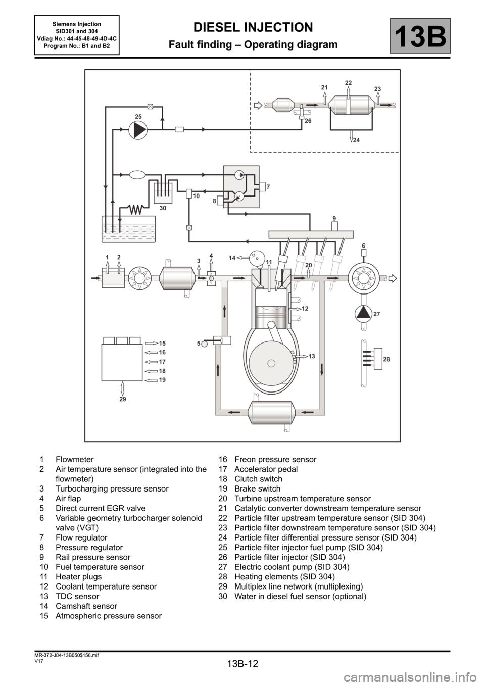
Fault finding – Operating diagram
1 Flowmeter
2 Air temperature sensor (integrated into the
flowmeter)
3 Turbocharging pressure sensor
4 Air flap
5 Direct current EGR valve
6 Variable geometry turbocharger solenoid
valve (VGT)
7 Flow regulator
8 Pressure regulator
9 Rail pressure sensor
10 Fuel temperature sensor
11 Heater plugs
12 Coolant temperature sensor
13 TDC sensor
14 Camshaft sensor
15 Atmospheric pressure sensor16 Freon pressure sensor
17 Accelerator pedal
18 Clutch switch
19 Brake switch
20 Turbine upstream temperature sensor
21 Catalytic converter downstream temperature sensor
22 Particle filter upstream temperature sensor (SID 304)
23 Particle filter downstream temperature sensor (SID 304)
24 Particle filter differential pressure sensor (SID 304)
25 Particle filter injector fuel pump (SID 304)
26 Particle filter injector (SID 304)
27 Electric coolant pump (SID 304)
28 Heating elements (SID 304)
29 Multiplex line network (multiplexing)
30 Water in diesel fuel sensor (optional)
MR-372-J84-13B050$156.mif
Siemens Injection
SID301 and 304
Vdiag No.: 44-45-48-49-4D-4C
Program No.: B1 and B2
Page 13 of 329
13B-13
MR-372-J84-13B050$195.mif
V17
13B
DIESEL INJECTION
Fault finding – Function
SYSTEM FLOWCHART
The high pressure injection system is designed to deliver a precise quantity of diesel fuel to the engine at a set
moment.
The Siemens VDO piezo Common Rail system used on the K9K Step 2 engine is a second generation Common Rail
injection system. Fuel pressure in the rail can reach a maximum of 1650 bar.
The Siemens VDO piezo Common Rail system uses injectors which are controlled by piezoelectric actuators.
The fuel is pressurised by means of a high pressure pump then sent to a rail which supplies the four injectors.
The system includes two subsystems, which have different fuel pressure levels:
●the low pressure system which includes the tank, diesel fuel filter, internal fuel transfer pump and injector
return pipes,
●the high pressure system which includes the high pressure pump, rail, injectors and high pressure pipes.
There are a number of sensors and regulating actuators for controlling and monitoring the entire system.
It is fitted with a 112- track (or 128- track for Kangoo II) SIEMENS computer (SID 301 and SID 304).
The system comprises:
– a priming bulb,
– a diesel filter,
– a high pressure pump (HPP) with a fuel pressure solenoid valve (PCV), a fuel flow solenoid valve (VCV) and an
internal fuel transfer pump (ITP, low pressure pump),
– an injector rail,
– a rail pressure sensor,
– four piezoelectric injectors,
– a fuel temperature sensor,
– a coolant temperature sensor,
– a camshaft sensor,
– a TDC sensor,
– a turbocharger pressure sensor,
– an exhaust gas recirculation solenoid valve with integrated position sensor (EGR),
– an accelerator pedal potentiometer,
– an atmospheric pressure sensor integrated into the injection computer,
– an air mass flowmeter with integrated air temperature sensor,
– an air damper valve (Vdiag 44, 45, 48, 49 and 4D only),
– a temperature sensor upstream of the turbine,
– an antipollution system:
●a temperature sensor upstream of the particle filter (Vdiag 45, 49, 4D only),
●a temperature sensor downstream of the particle filter (Vdiag 45, 49, 4D only),
●a particle filter differential pressure sensor (Vdiag 45, 49, 4D only),
●a particle filter injector (Vdiag 45, 49, 4D only),
●a particle filter (Vdiag 45, 49, 4D only),
– a temperature sensor downstream of the catalytic converter,
– an electric fuel pump,
– an electric coolant pump (Vdiag 45, 49, 4D only),
– four heating elements and their control unit (Vdiag 45, 49, 4D only),
– four heater plugs,
– a water in the fuel detection sensor (optional).
MR-372-J84-13B050$195.mif
Siemens Injection
SID301 and 304
Vdiag No.: 44-45-48-49-4D-4C
Program No.: B1 and B2
Page 18 of 329
13B-18
MR-372-J84-13B050$195.mif
V17
Siemens Injection
SID301 and 304
Vdiag No.: 44-45-48-49-4D-4C
Program No.: B1 and B2DIESEL INJECTION
Fault finding – Function13B
MANAGEMENT OF PRE/POSTHEATING
Pre-postheating management involves controlling the heater plugs and the heater plugs indicator light on the
instrument panel (via the multiplex network). The heater plugs are activated by a preheating unit and the power is
provided by the battery.
When the ignition is switched on, the preheating period is activated; the indicator light comes on for a period
dependent on the battery voltage, atmospheric pressure and coolant temperature.
When the coolant temperature is below a certain threshold, a postheating function enables combustion stability,
and thereby engine operation, to be improved (reduction in unburned fuel and pollutant emissions).
MANAGEMENT OF ENGINE COOLANT TEMPERATURE
Engine cooling is guaranteed by a 2-speed fan assembly (GMV) (slow: GMV1 and fast: GMV2).
The injection computer requests the UPC to actuate them via the multiplex network.
To provide cooling:
– Engine running:
GMV1 is activated when the coolant temperature exceeds 96°C and is deactivated when it drops below 94°C.
GMV2 is activated when the coolant temperature exceeds 104°C and is deactivated when it drops below 102°C.
If the engine coolant temperature exceeds the warning threshold of 120°C, the injection computer requests the
instrument panel computer, via the multiplex network, to switch on the coolant temperature warning light. The
warning stops if the coolant temperature drops below 117 ° C.
If the engine coolant temperature exceeds the threshold of 11 5 ° C, the injection computer requests the UPC
computer, via the multiplex network, to switch off the air conditioning compressor so as to reduce the load on the
engine and attempt to limit its rise in temperature. The cut-off request is cancelled if the coolant temperature drops
below 110°C.
If a fault in the coolant temperature sensor circuit is detected, the injection computer requests that the coolant
temperature warning light is lit and that GMV2 is activated.
In addition to engine management, the injection computer centralises the cooling requirements for the air
conditioning and automatic gearbox/sequential gearbox functions (if fitted to the vehicle).
OTHER HOSTED FUNCTIONS
The other functions hosted by the computer are:
– Multiplex line.
– ADAC (Trip Computer).
– Trip Computer Display.
– Engine immobiliser.
– Airbag.
– Engine stop management.
– Starter management.
– Air conditioning.
– Cruise control/speed limiter.
Page 24 of 329
13B-24
MR-372-J84-13B050$195.mif
V17
Siemens Injection
SID301 and 304
Vdiag No.: 44-45-48-49-4D-4C
Program No.: B1 and B2DIESEL INJECTION
Fault finding – Function13B
Cruise control/speed limiter on/off switch:
This switch turns the cruise control/speed limiter on or off.
Water in diesel fuel sensor (optional):
This sensor indicates if water is present in the diesel.
Fan unit relay:
This relay actuates the motor-driven fan assemblies when a temperature threshold has been exceeded.
Accelerator potentiometer:
The accelerator potentiometer informs the computer about the position of the accelerator pedal (engine load).
Brake pedal switch:
The brake pedal switch informs the computer about the pedal status.
Clutch pedal switch:
The clutch pedal switch informs the computer about the pedal status.
Particle filter injector:
The particle filter injector is a low pressure injector. This injector allows the temperature of the second catalytic
converter to be raised to assist with regeneration of the particle filter (Vdiag 45, 49, 4D only).
Only on Kangoo 2: an evaporator plate is present at the particle filter injector outlet, at the level of the bracket
between the exhaust pipe and the catalytic converter.
Heating elements:
The heating elements heat the engine coolant to enhance user comfort (Vdiag 45, 49, 4D only).
Heater plugs:
The heater plugs preheat the combustion chamber so that the explosion of the fuel mixture occurs under the best
conditions to start the engine.
Page 50 of 329
13B-50
MR-372-J84-13B050$390.mif
V17
DIESEL INJECTION
Fault finding – Interpretation of faults
Siemens Injection
SID301 and 304
Vdiag No. 44-45-48-49-4D-4C
Program No.: B1 and B2
13B
DF017
PRESENT
OR
STOREDPRE-POSTHEATING UNIT CONTROL CIRCUIT
CC.0 : Short circuit to earth
CC.1 : Short circuit to + 12 V
CO : Open circuit
NOTESConditions for applying the fault finding procedure to a stored fault:
The fault is declared present after attempts have been made to start the engine.
Special notes:
If the fault is present, it will be difficult or impossible to start the vehicle when cold, or
preheating will be continuous with damage to the heater plugs.
Use CLIO III, MODUS, MEGANE II ph2, SCENIC II ph2 and KANGOO II Wiring
diagrams Technical Note.
Check the connection and condition of the connector for the preheating unit, component code257 or 980 (see
MR 392, 385, 364, 370 and 417, Mechanical, 13C, Preheating, Pre-post heating unit:
Removal - Refitting), the supply cables for the heater plugs (see MR 392, 385, 364, 370 and 417,
Mechanical, 13C, Preheating, Heater plugs: Removal - Refitting) and the injection computer connector,
component code120 (see MR 392, 385, 364, 370 and 417, Mechanical, 13B, Diesel injection, Diesel injection
computer: Removal - Refitting).
If the connectors are faulty and if there is a repair procedure (see Technical Note 6015A, Repairing electrical
wiring, Wiring: Precautions for repair) repair the connector(s); otherwise, replace the wiring.
Check the condition of the power supply fuseF2 (70A) on the power supply fuse board component code777.
Check the insulation, continuity and the absence of interference resistance on the following connections:
–3FF between components257 or 980 and 120,
–3FY between components257 or 980 and 120,
–BP35 between components257 or 980 and 777.
If the connection(s) are faulty and there is a repair method (see Technical Note 6015A, Repairing electrical
wiring, Wiring: Precautions for repair), repair the wiring, otherwise replace it.
If these connections are correct, replace the preheating unit (see MR 392, 385, 364, 370 and 417, Mechanical,
13C, Preheating, Pre-post heating unit: Removal - Refitting).
If the fault is still present, contact the Techline.
AFTER REPAIRDeal with any faults displayed by the diagnostic tool.
Clear the computer fault memory.
Carry out a road test followed by another check with the diagnostic tool.
SID301_V44_DF017 / SID304_V45_DF017 / SID301_V48_DF017 / SID304_V49_DF017 / SID304_V4D_DF017 / SID301_V4C_DF017
Page 51 of 329
13B-51
MR-372-J84-13B050$390.mif
V17
DIESEL INJECTION
Fault finding – Interpretation of faults
Siemens Injection
SID301 and 304
Vdiag No. 44-45-48-49-4D-4C
Program No.: B1 and B2
13B
DF025
PRESENT
OR
STOREDPRE-POSTHEATING UNIT DIAGNOSTIC LINE
CC.0 : Short circuit to earth
C0.1 : Open circuit or short circuit to + 12 V
NOTESConditions for applying the fault finding procedure to a stored fault:
The fault is declared present after several attempts have been made to start the
engine.
Special notes:
If the fault is present, it will be difficult or impossible to start the vehicle when cold, or
preheating will be continuous with damage to the heater plugs.
Use CLIO III, MODUS, MEGANE II ph2, SCENIC II ph2 and KANGOO II Wiring
diagrams Technical Note.
Check the connection and condition of the connector for the preheating unit, component code257 or 980 (see
MR 392, 385, 364, 370 and 417, Mechanical, 13C, Preheating, Pre-post heating unit: Removal - Refitting)
and the supply cables for the heater plugs, component code257 (see MR 392, 385, 364, 370 and 417,
Mechanical, 13C, Pre-heating, Heater plugs: Removal - Refitting).
If the connectors are faulty and if there is a repair procedure (see Technical Note 6015A, Repairing electrical
wiring, Wiring: Precautions for repair) repair the connector(s); otherwise, replace the wiring.
Check the connection and condition of the connectors for the heater plugs, component codes680, 681, 682 and
683 (see MR 392, 385, 364, 370 and 417, Mechanical, 13C, Pre-heating, Heater plugs: Removal - Refitting)
and the injection computer connector, component code120 (see MR 392, 385, 364, 370 and 417, Mechanical,
13B, Diesel injection, Diesel injection computer: Removal - Refitting).
If the connectors are faulty and if there is a repair procedure (see Technical Note 6015A, Repairing electrical
wiring, Wiring: Precautions for repair) repair the connector(s); otherwise, replace the wiring.
Measure the resistance of the heater plugs, component codes680, 681, 682 and 683.
If the resistance is not 0.6Ω at +20°C, replace the plug(s) (see MR 392, 385, 364, 370 and 417, Mechanical,
13C, Pre-heating, Heater plugs: Removal - Refitting).
AFTER REPAIRDeal with any faults displayed by the diagnostic tool.
Clear the computer fault memory.
Carry out a road test followed by another check with the diagnostic tool.
SID301_V44_DF025 / SID304_V45_DF025 / SID301_V48_DF025 / SID304_V49_DF025 / SID304_V4D_DF025 / SID301_V4C_DF025
Page 79 of 329
13B-79
MR-372-J84-13B050$429.mif
V17
DIESEL INJECTION
Fault finding – Interpretation of faults
Siemens Injection
SID301 and 304
Vdiag No.: 44-45-48-49-4D-4C
Program No.: B1 and B2
13B
DF238
PRESENT
OR
STOREDTHERMOPLUNGER NO. 3 RELAY CIRCUIT
CC.0 : Short circuit to earth
CC.1 : Short circuit to + 12 V
CO : Open circuit
NOTESConditions for applying the fault finding procedure to a stored fault:
The fault becomes present after starting the engine.
If the fault is present:
CC.0: The water heater interface unit is permanently actuated.
CC.1: The water heater interface unit is not actuated.
The level 1 fault warning light is lit on the instrument panel.
Use CLIO III, MODUS, MEGANE II ph2, SCENIC II ph2 and Kangoo II Wiring
diagrams Technical Note.
Check the connection and condition of the thermoplunger unit connector, component code 1550 (see MR 392,
385, 364, 370 and 417, Mechanical, 61A, Heating system, Heating system: List and location of
components).
If the connector is faulty and there is a repair procedure (see Technical Note 6015A, Electrical wiring repair,
Wiring: Precautions for repair), repair the connector, otherwise replace the wiring.
Check the connection and condition of the injection computer connector, component code 120 (see MR 392,
385, 364, 370 and 417, Mechanical, 13B, Diesel injection, Diesel injection computer: Removal - Refitting).
If the connector is faulty and there is a repair procedure (see Technical Note 6015A, Electrical wiring repair,
Wiring: Precautions for repair), repair the connector, otherwise replace the wiring.
With the ignition on, check for + 12 V on connections BP35 and BP36 of the thermoplunger unit, component
code 1550.
Check the continuity, insulation and the absence of interference resistance on the following connection:
–3JAB between components1550 and 120.
If the connection is faulty and there is a repair procedure (see Technical Note 6015A, Electrical wiring repair,
Wiring: Precautions for repair), repair the wiring, otherwise replace it.
If the fault is still present, contact the Techline.
AFTER REPAIRDeal with any faults displayed by the diagnostic tool.
Clear the computer fault memory.
Carry out a road test followed by another check with the diagnostic tool.
SID304_V4D_DF238 / SID301_V4C_DF238
Page 80 of 329
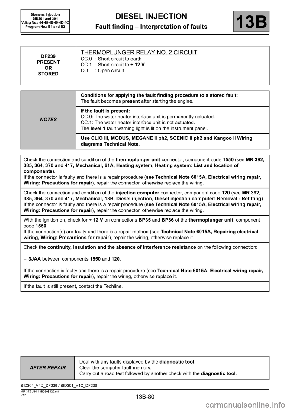
13B-80
MR-372-J84-13B050$429.mif
V17
DIESEL INJECTION
Fault finding – Interpretation of faults
Siemens Injection
SID301 and 304
Vdiag No.: 44-45-48-49-4D-4C
Program No.: B1 and B2
13B
DF239
PRESENT
OR
STOREDTHERMOPLUNGER RELAY NO. 2 CIRCUIT
CC.0 : Short circuit to earth
CC.1 : Short circuit to + 12 V
CO : Open circuit
NOTESConditions for applying the fault finding procedure to a stored fault:
The fault becomes present after starting the engine.
If the fault is present:
CC.0: The water heater interface unit is permanently actuated.
CC.1: The water heater interface unit is not actuated.
The level 1 fault warning light is lit on the instrument panel.
Use CLIO III, MODUS, MEGANE II ph2, SCENIC II ph2 and Kangoo II Wiring
diagrams Technical Note.
Check the connection and condition of the thermoplunger unit connector, component code 1550 (see MR 392,
385, 364, 370 and 417, Mechanical, 61A, Heating system, Heating system: List and location of
components).
If the connector is faulty and there is a repair procedure (see Technical Note 6015A, Electrical wiring repair,
Wiring: Precautions for repair), repair the connector, otherwise replace the wiring.
Check the connection and condition of the injection computer connector, component code 120 (see MR 392,
385, 364, 370 and 417, Mechanical, 13B, Diesel injection, Diesel injection computer: Removal - Refitting).
If the connector is faulty and there is a repair procedure (see Technical Note 6015A, Electrical wiring repair,
Wiring: Precautions for repair), repair the connector, otherwise replace the wiring.
With the ignition on, check for + 12 V on connections BP35 and BP36 of the thermoplunger unit, component
code 1550.
If the connection(s) are faulty and there is a repair method (see Technical Note 6015A, Repairing electrical
wiring, Wiring: Precautions for repair), repair the wiring, otherwise replace it.
Check the continuity, insulation and the absence of interference resistance on the following connection:
–3JAA between components 1550 and 120.
If the connection is faulty and there is a repair procedure (see Technical Note 6015A, Electrical wiring repair,
Wiring: Precautions for repair), repair the wiring, otherwise replace it.
If the fault is still present, contact the Techline.
AFTER REPAIRDeal with any faults displayed by the diagnostic tool.
Clear the computer fault memory.
Carry out a road test followed by another check with the diagnostic tool.
SID304_V4D_DF239 / SID301_V4C_DF239
Page 81 of 329
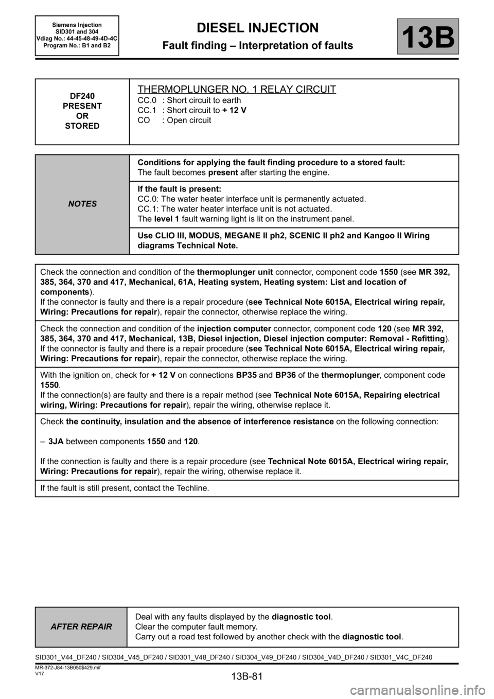
13B-81
MR-372-J84-13B050$429.mif
V17
DIESEL INJECTION
Fault finding – Interpretation of faults
Siemens Injection
SID301 and 304
Vdiag No.: 44-45-48-49-4D-4C
Program No.: B1 and B2
13B
DF240
PRESENT
OR
STOREDTHERMOPLUNGER NO. 1 RELAY CIRCUIT
CC.0 : Short circuit to earth
CC.1 : Short circuit to + 12 V
CO : Open circuit
NOTESConditions for applying the fault finding procedure to a stored fault:
The fault becomes present after starting the engine.
If the fault is present:
CC.0: The water heater interface unit is permanently actuated.
CC.1: The water heater interface unit is not actuated.
The level 1 fault warning light is lit on the instrument panel.
Use CLIO III, MODUS, MEGANE II ph2, SCENIC II ph2 and Kangoo II Wiring
diagrams Technical Note.
Check the connection and condition of the thermoplunger unit connector, component code 1550 (see MR 392,
385, 364, 370 and 417, Mechanical, 61A, Heating system, Heating system: List and location of
components).
If the connector is faulty and there is a repair procedure (see Technical Note 6015A, Electrical wiring repair,
Wiring: Precautions for repair), repair the connector, otherwise replace the wiring.
Check the connection and condition of the injection computer connector, component code 120 (see MR 392,
385, 364, 370 and 417, Mechanical, 13B, Diesel injection, Diesel injection computer: Removal - Refitting).
If the connector is faulty and there is a repair procedure (see Technical Note 6015A, Electrical wiring repair,
Wiring: Precautions for repair), repair the connector, otherwise replace the wiring.
With the ignition on, check for + 12 V on connections BP35 and BP36 of the thermoplunger, component code
1550.
If the connection(s) are faulty and there is a repair method (see Technical Note 6015A, Repairing electrical
wiring, Wiring: Precautions for repair), repair the wiring, otherwise replace it.
Check the continuity, insulation and the absence of interference resistance on the following connection:
–3JA between components 1550 and 120.
If the connection is faulty and there is a repair procedure (see Technical Note 6015A, Electrical wiring repair,
Wiring: Precautions for repair), repair the wiring, otherwise replace it.
If the fault is still present, contact the Techline.
AFTER REPAIRDeal with any faults displayed by the diagnostic tool.
Clear the computer fault memory.
Carry out a road test followed by another check with the diagnostic tool.
SID301_V44_DF240 / SID304_V45_DF240 / SID301_V48_DF240 / SID304_V49_DF240 / SID304_V4D_DF240 / SID301_V4C_DF240