technical data RENAULT SCENIC 2011 J95 / 3.G Engine And Peripherals Siemens Injection Workshop Manual
[x] Cancel search | Manufacturer: RENAULT, Model Year: 2011, Model line: SCENIC, Model: RENAULT SCENIC 2011 J95 / 3.GPages: 329, PDF Size: 1.71 MB
Page 26 of 329

13B-26
MR-372-J84-13B050$273.mif
V17
13B
DIESEL INJECTION
Fault finding – Replacement of components
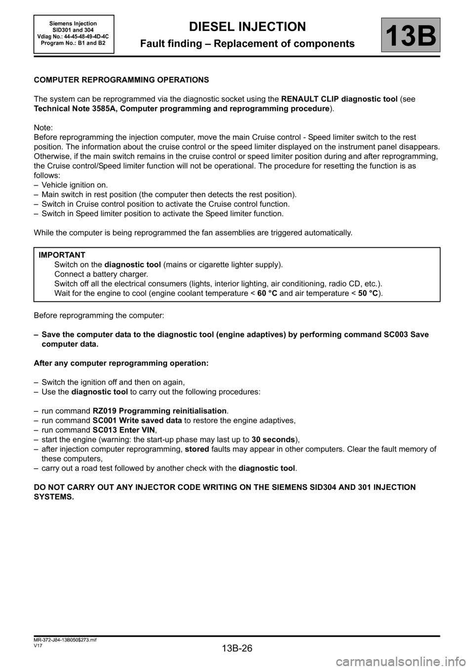
COMPUTER REPROGRAMMING OPERATIONS
The system can be reprogrammed via the diagnostic socket using the RENAULT CLIP diagnostic tool (see
Technical Note 3585A, Computer programming and reprogramming procedure).
Note:
Before reprogramming the injection computer, move the main Cruise control - Speed limiter switch to the rest
position. The information about the cruise control or the speed limiter displayed on the instrument panel disappears.
Otherwise, if the main switch remains in the cruise control or speed limiter position during and after reprogramming,
the Cruise control/Speed limiter function will not be operational. The procedure for resetting the function is as
follows:
– Vehicle ignition on.
– Main switch in rest position (the computer then detects the rest position).
– Switch in Cruise control position to activate the Cruise control function.
– Switch in Speed limiter position to activate the Speed limiter function.
While the computer is being reprogrammed the fan assemblies are triggered automatically.
Before reprogramming the computer:
– Save the computer data to the diagnostic tool (engine adaptives) by performing command SC003 Save
computer data.
After any computer reprogramming operation:
– Switch the ignition off and then on again,
–Use the diagnostic tool to carry out the following procedures:
– run command RZ019 Programming reinitialisation.
– run command SC001 Write saved data to restore the engine adaptives,
– run command SC013 Enter VIN,
– start the engine (warning: the start-up phase may last up to 30 seconds),
– after injection computer reprogramming, stored faults may appear in other computers. Clear the fault memory of
these computers,
– carry out a road test followed by another check with the diagnostic tool.
DO NOT CARRY OUT ANY INJECTOR CODE WRITING ON THE SIEMENS SID304 AND 301 INJECTION
SYSTEMS.IMPORTANT
Switch on the diagnostic tool (mains or cigarette lighter supply).
Connect a battery charger.
Switch off all the electrical consumers (lights, interior lighting, air conditioning, radio CD, etc.).
Wait for the engine to cool (engine coolant temperature < 60 °C and air temperature < 50 °C).
MR-372-J84-13B050$273.mif
Siemens Injection
SID301 and 304
Vdiag No.: 44-45-48-49-4D-4CProgram No.: B1 and B2
Page 28 of 329

13B-28
MR-372-J84-13B050$273.mif
V17
Siemens Injection
SID301 and 304
Vdiag No.: 44-45-48-49-4D-4C
Program No.: B1 and B2DIESEL INJECTION
Fault finding – Replacement of components13B
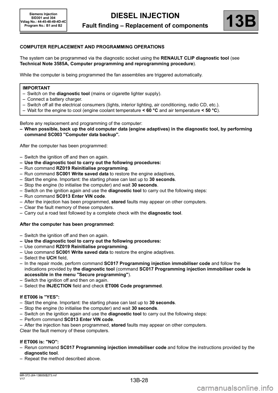
COMPUTER REPLACEMENT AND PROGRAMMING OPERATIONS
The system can be programmed via the diagnostic socket using the RENAULT CLIP diagnostic tool (see
Technical Note 3585A, Computer programming and reprogramming procedure).
While the computer is being programmed the fan assemblies are triggered automatically.
Before any replacement and programming of the computer:
– When possible, back up the old computer data (engine adaptives) in the diagnostic tool, by performing
command SC003 "Computer data backup".
After the computer has been programmed:
– Switch the ignition off and then on again.
– Use the diagnostic tool to carry out the following procedures:
– Run command RZ019 Reinitialise programming.
– Run command SC001 Write saved data to restore the engine adaptives,
– Start the engine. Important: the starting phase can last up to 30 seconds.
– Stop the engine (to initialise the computer) and wait 30 seconds.
– Switch on the ignition again and use the diagnostic tool to carry out the following steps:
– Run command SC013 Enter VIN code.
– After the injection has been programmed, stored faults may appear on other computers.
– Clear the fault memory of these computers.
– Carry out a road test followed by a complete check with the diagnostic tool.
After the computer has been programmed:
– Switch the ignition off and then on again.
– Use the diagnostic tool to carry out the following procedures:
– Use command RZ019 Reinitialise programming.
– Use command SC001 Write saved data to restore the engine adaptives.
– Select the UCH field,
– In the repair mode, perform command SC017 Programming injection immobiliser code and follow the
indications provided by the diagnostic tool (command SC017 Programming injection immobiliser code is
accessible in the menu "Secure programming").
– Switch the ignition off and then on again.
– Select the INJECTION field and check ET006 Code programmed.
If ET006 is "YES":
– Start the engine. Important: the starting phase can last up to 30 seconds.
– Stop the engine (to initialise the computer) and wait 30 seconds.
– Switch on the ignition again and use the diagnostic tool to carry out the following steps:
– Perform command SC013 Enter VIN code.
– After the injection has been programmed, stored faults may appear on other computers.
Clear the fault memory of these computers.
If ET006 is: "NO":
– Rerun command SC017 Programming injection immobiliser code and follow the instructions provided by the
diagnostic tool.
– Repeat the method described above.IMPORTANT
– Switch on the diagnostic tool (mains or cigarette lighter supply).
– Connect a battery charger.
– Switch off all the electrical consumers (lights, interior lighting, air conditioning, radio CD, etc.).
– Wait for the engine to cool (engine coolant temperature < 60 °C and air temperature < 50 °C).
Page 39 of 329

13B-39
MR-372-J84-13B050$390.mif
V17
DIESEL INJECTION
Fault finding – Interpretation of faults
Siemens Injection
SID301 and 304
Vdiag No. 44-45-48-49-4D-4C
Program No.: B1 and B2
13B
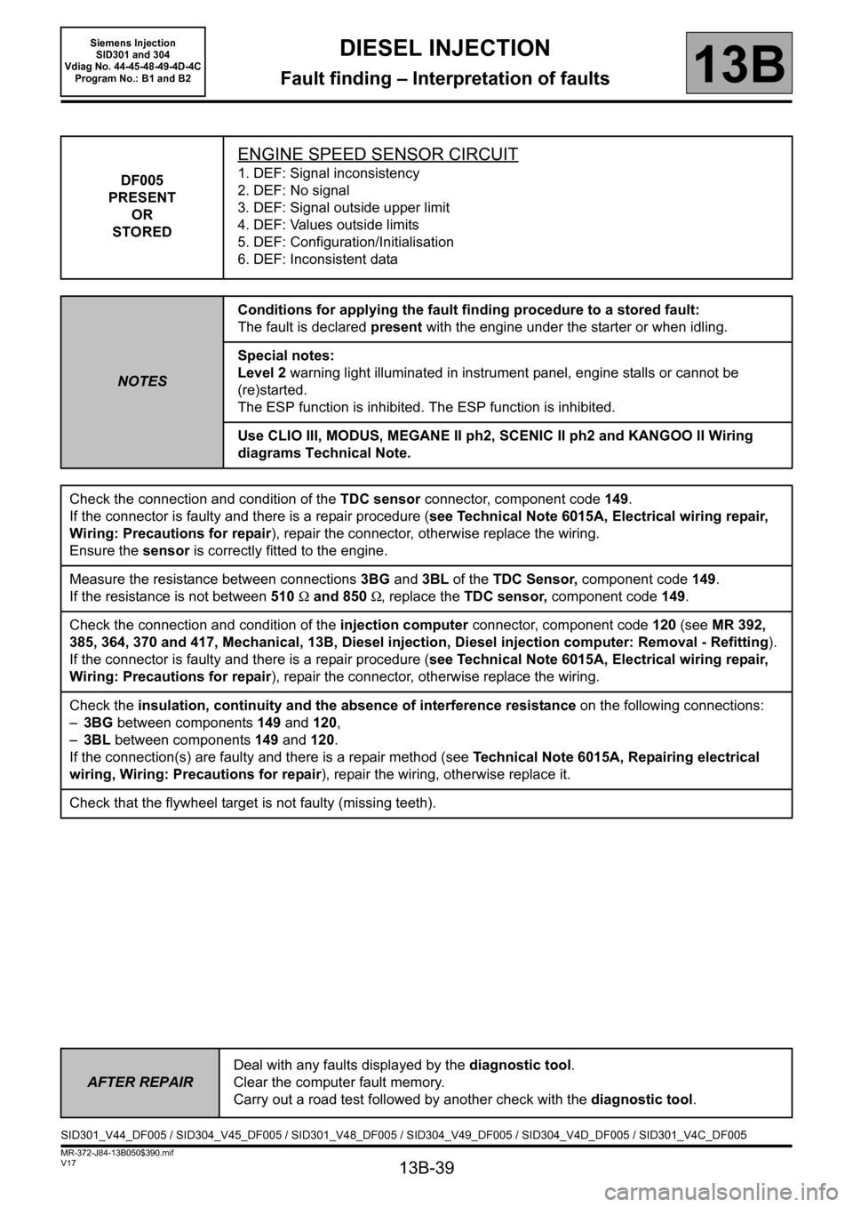
DF005
PRESENT
OR
STORED
ENGINE SPEED SENSOR CIRCUIT
1. DEF: Signal inconsistency
2. DEF: No signal
3. DEF: Signal outside upper limit
4. DEF: Values outside limits
5. DEF: Configuration/Initialisation
6. DEF: Inconsistent data
NOTESConditions for applying the fault finding procedure to a stored fault:
The fault is declared present with the engine under the starter or when idling.
Special notes:
Level 2 warning light illuminated in instrument panel, engine stalls or cannot be
(re)started.
The ESP function is inhibited. The ESP function is inhibited.
Use CLIO III, MODUS, MEGANE II ph2, SCENIC II ph2 and KANGOO II Wiring
diagrams Technical Note.
Check the connection and condition of the TDC sensor connector, component code 149.
If the connector is faulty and there is a repair procedure (see Technical Note 6015A, Electrical wiring repair,
Wiring: Precautions for repair), repair the connector, otherwise replace the wiring.
Ensure the sensor is correctly fitted to the engine.
Measure the resistance between connections3BG and 3BL of the TDC Sensor, component code149.
If the resistance is not between 510Ω and 850Ω, replace the TDC sensor, component code149.
Check the connection and condition of the injection computer connector, component code120 (see MR 392,
385, 364, 370 and 417, Mechanical, 13B, Diesel injection, Diesel injection computer: Removal - Refitting).
If the connector is faulty and there is a repair procedure (see Technical Note 6015A, Electrical wiring repair,
Wiring: Precautions for repair), repair the connector, otherwise replace the wiring.
Check the insulation, continuity and the absence of interference resistance on the following connections:
–3BG between components 149 and 120,
–3BL between components 149 and 120.
If the connection(s) are faulty and there is a repair method (see Technical Note 6015A, Repairing electrical
wiring, Wiring: Precautions for repair), repair the wiring, otherwise replace it.
Check that the flywheel target is not faulty (missing teeth).
AFTER REPAIRDeal with any faults displayed by the diagnostic tool.
Clear the computer fault memory.
Carry out a road test followed by another check with the diagnostic tool.
SID301_V44_DF005 / SID304_V45_DF005 / SID301_V48_DF005 / SID304_V49_DF005 / SID304_V4D_DF005 / SID301_V4C_DF005