charge circuit RENAULT SCENIC 2011 J95 / 3.G Engine And Peripherals Owner's Manual
[x] Cancel search | Manufacturer: RENAULT, Model Year: 2011, Model line: SCENIC, Model: RENAULT SCENIC 2011 J95 / 3.GPages: 198, PDF Size: 0.85 MB
Page 161 of 198
13B-161V4 MR-372-J84-13B000$120.mif
DIESEL INJECTION
Fault finding – Tests13B
DDCR INJECTION
Vdiag No.: 44, 48
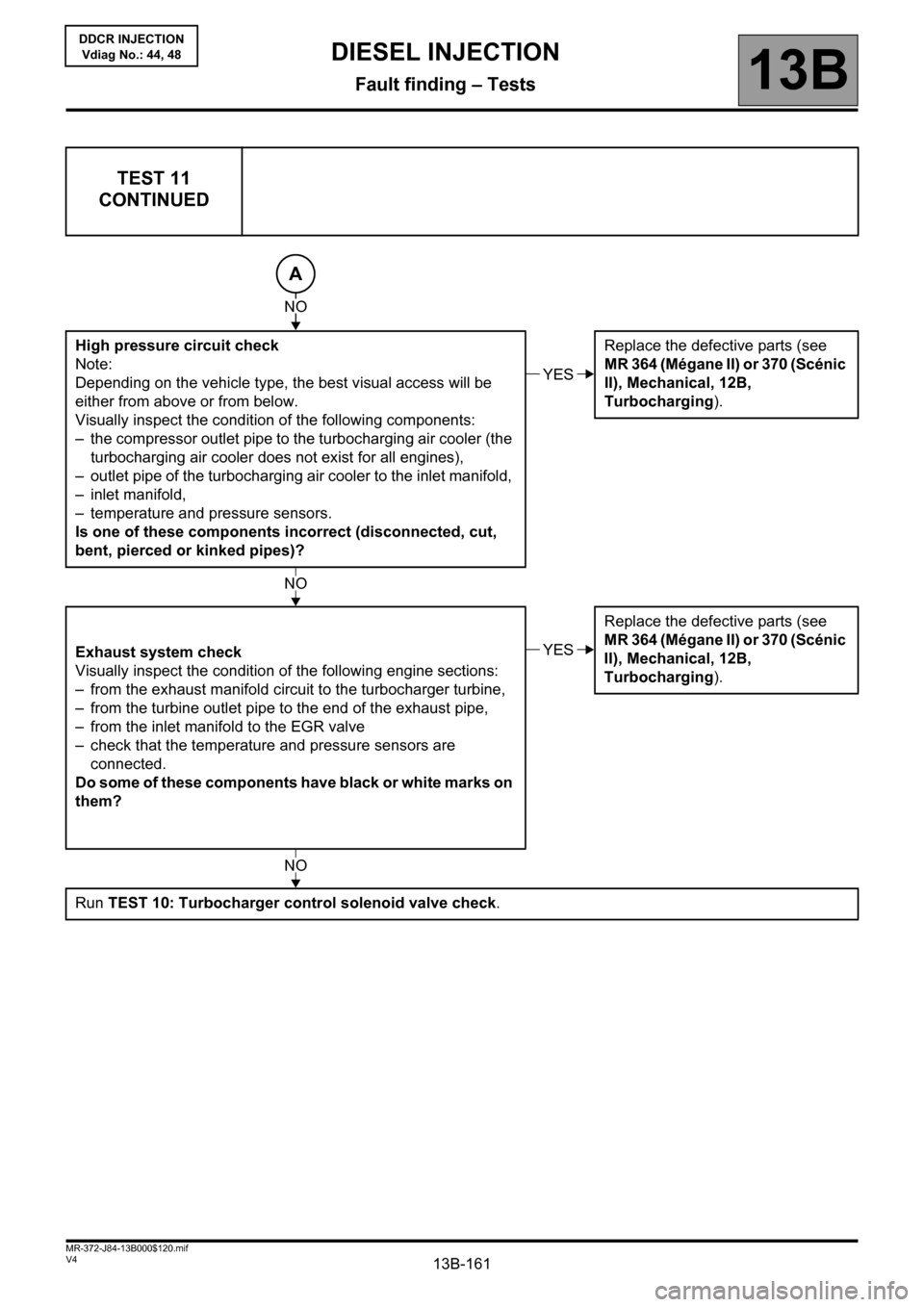
TEST 11
CONTINUED
High pressure circuit check
Note:
Depending on the vehicle type, the best visual access will be
either from above or from below.
Visually inspect the condition of the following components:
– the compressor outlet pipe to the turbocharging air cooler (the
turbocharging air cooler does not exist for all engines),
– outlet pipe of the turbocharging air cooler to the inlet manifold,
– inlet manifold,
– temperature and pressure sensors.
Is one of these components incorrect (disconnected, cut,
bent, pierced or kinked pipes)?Replace the defective parts (see
MR 364 (Mégane II) or 370 (Scénic
II), Mechanical, 12B,
Turbocharging).
Exhaust system check
Visually inspect the condition of the following engine sections:
– from the exhaust manifold circuit to the turbocharger turbine,
– from the turbine outlet pipe to the end of the exhaust pipe,
– from the inlet manifold to the EGR valve
– check that the temperature and pressure sensors are
connected.
Do some of these components have black or white marks on
them? Replace the defective parts (see
MR 364 (Mégane II) or 370 (Scénic
II), Mechanical, 12B,
Turbocharging).
Run TEST 10: Turbocharger control solenoid valve check.
A
NO
YES
NO
YES
NO
Page 177 of 198
13B-177
AFTER REPAIRCarry out a road test, then check with the diagnostic tool.
V4 MR-372-J84-13B000$140.mif
DIESEL INJECTION
Fault finding – Fault finding charts13B
InjectionDDCR
Vdiag No.: 44, 48
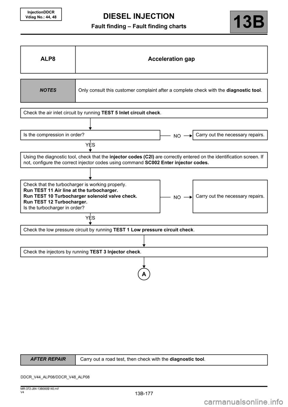
ALP8 Acceleration gap
NOTESOnly consult this customer complaint after a complete check with the diagnostic tool.
Check the air inlet circuit by running TEST 5 Inlet circuit check.
Is the compression in order? Carry out the necessary repairs.
Using the diagnostic tool, check that the injector codes (C2I) are correctly entered on the identification screen. If
not, configure the correct injector codes using command SC002 Enter injector codes.
Check that the turbocharger is working properly.
Run TEST 11 Air line at the turbocharger.
Run TEST 10 Turbocharger solenoid valve check.
Run TEST 12 Turbocharger.
Is the turbocharger in order?Carry out the necessary repairs.
Check the low pressure circuit by running TEST 1 Low pressure circuit check.
Check the injectors by running TEST 3 Injector check.
NO
YES
NO
YES
A
DDCR_V44_ALP08/DDCR_V48_ALP08
Page 184 of 198
13B-184
AFTER REPAIRCarry out a road test, then check with the diagnostic tool.
V4 MR-372-J84-13B000$140.mif
DIESEL INJECTION
Fault finding – Fault finding charts13B
InjectionDDCR
Vdiag No.: 44, 48
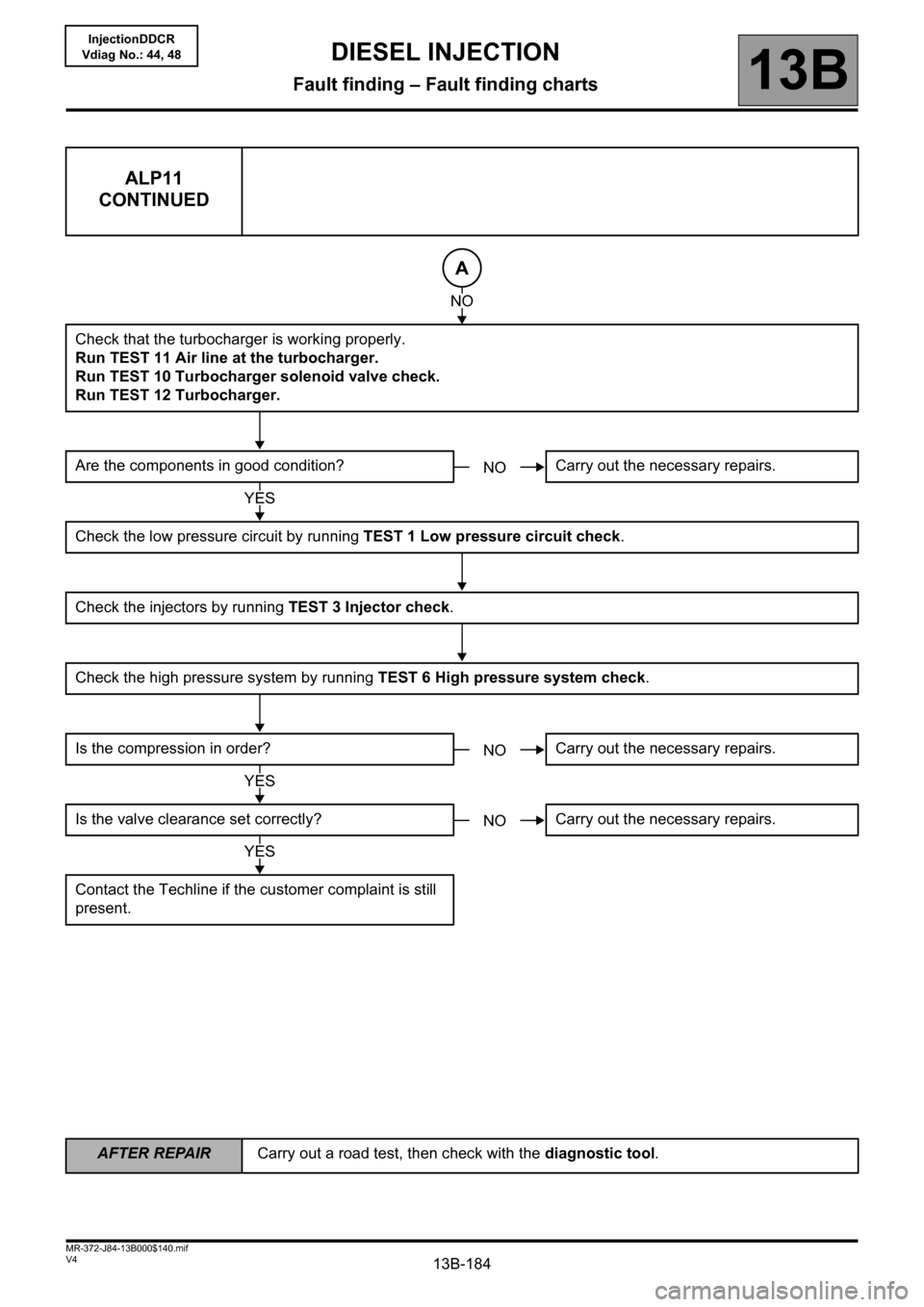
ALP11
CONTINUED
Check that the turbocharger is working properly.
Run TEST 11 Air line at the turbocharger.
Run TEST 10 Turbocharger solenoid valve check.
Run TEST 12 Turbocharger.
Are the components in good condition? Carry out the necessary repairs.
Check the low pressure circuit by running TEST 1 Low pressure circuit check.
Check the injectors by running TEST 3 Injector check.
Check the high pressure system by running TEST 6 High pressure system check.
Is the compression in order? Carry out the necessary repairs.
Is the valve clearance set correctly? Carry out the necessary repairs.
Contact the Techline if the customer complaint is still
present.
A
NO
NO
YES
NO
YES
NO
YES
Page 193 of 198
13B-193
AFTER REPAIRCarry out a road test, then check with the diagnostic tool.
V4 MR-372-J84-13B000$140.mif
DIESEL INJECTION
Fault finding – Fault finding charts13B
InjectionDDCR
Vdiag No.: 44, 48
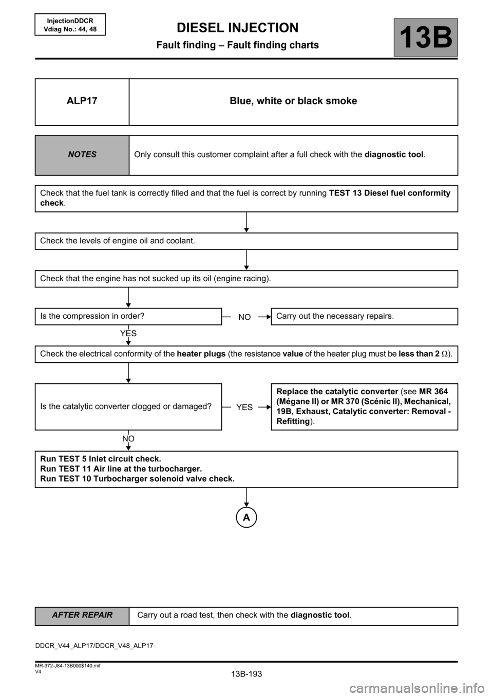
ALP17 Blue, white or black smoke
NOTESOnly consult this customer complaint after a full check with the diagnostic tool.
Check that the fuel tank is correctly filled and that the fuel is correct by running TEST 13 Diesel fuel conformity
check.
Check the levels of engine oil and coolant.
Check that the engine has not sucked up its oil (engine racing).
Is the compression in order? Carry out the necessary repairs.
Check the electrical conformity of the heater plugs (the resistance value of the heater plug must be less than 2 Ω).
Is the catalytic converter clogged or damaged?Replace the catalytic converter (see MR 364
(Mégane II) or MR 370 (Scénic II), Mechanical,
19B, Exhaust, Catalytic converter: Removal -
Refitting).
Run TEST 5 Inlet circuit check.
Run TEST 11 Air line at the turbocharger.
Run TEST 10 Turbocharger solenoid valve check.
NO
YES
YES
NO
A
DDCR_V44_ALP17/DDCR_V48_ALP17
Page 194 of 198
13B-194
AFTER REPAIRCarry out a road test, then check with the diagnostic tool.
V4 MR-372-J84-13B000$140.mif
DIESEL INJECTION
Fault finding – Fault finding charts13B
InjectionDDCR
Vdiag No.: 44, 48
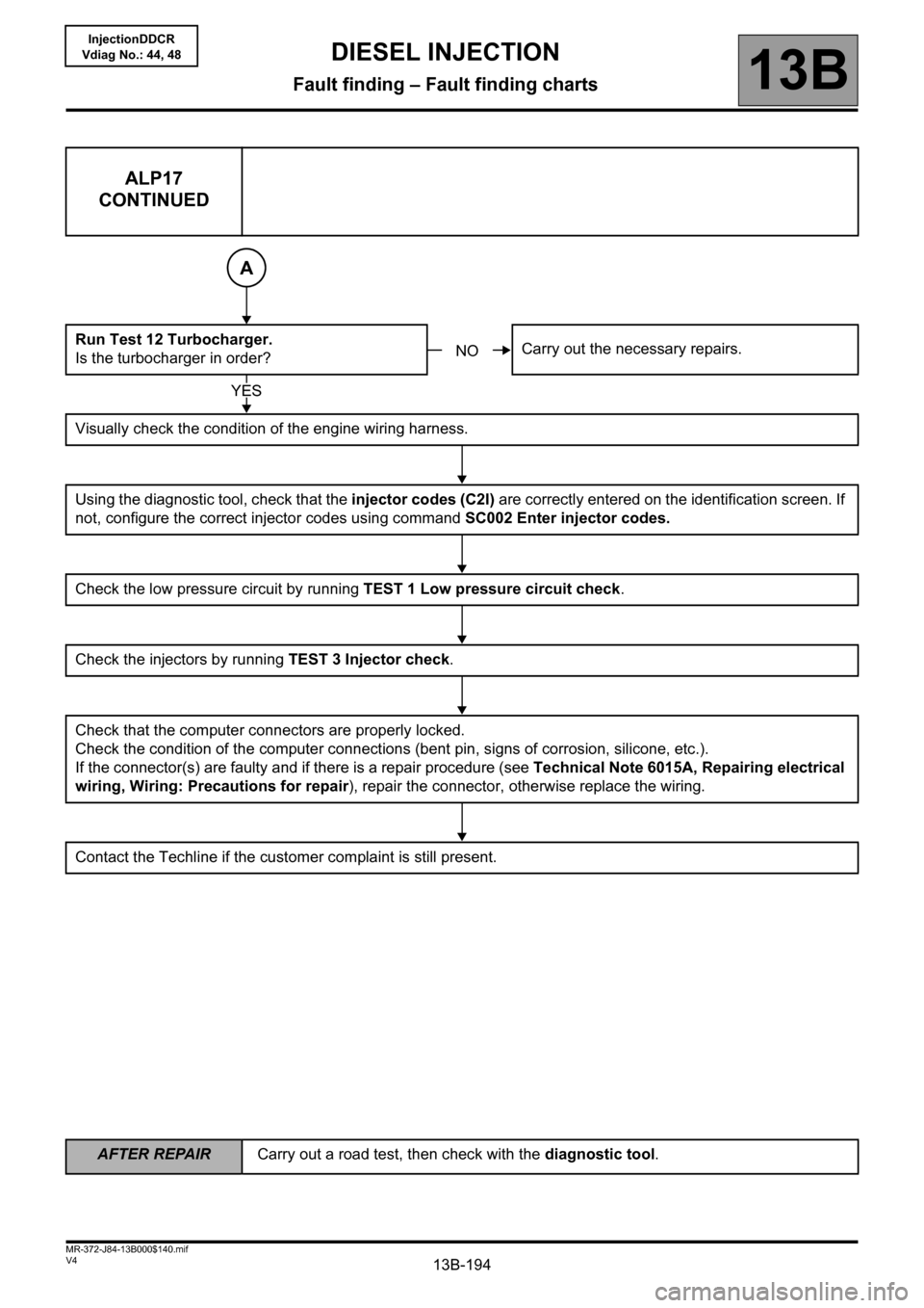
ALP17
CONTINUED
Run Test 12 Turbocharger.
Is the turbocharger in order?Carry out the necessary repairs.
Visually check the condition of the engine wiring harness.
Using the diagnostic tool, check that the injector codes (C2I) are correctly entered on the identification screen. If
not, configure the correct injector codes using command SC002 Enter injector codes.
Check the low pressure circuit by running TEST 1 Low pressure circuit check.
Check the injectors by running TEST 3 Injector check.
Check that the computer connectors are properly locked.
Check the condition of the computer connections (bent pin, signs of corrosion, silicone, etc.).
If the connector(s) are faulty and if there is a repair procedure (see Technical Note 6015A, Repairing electrical
wiring, Wiring: Precautions for repair), repair the connector, otherwise replace the wiring.
Contact the Techline if the customer complaint is still present.
A
NO
YES
Page 195 of 198
13B-195
AFTER REPAIRCarry out a road test, then check with the diagnostic tool.
V4 MR-372-J84-13B000$140.mif
DIESEL INJECTION
Fault finding – Fault finding charts13B
InjectionDDCR
Vdiag No.: 44, 48
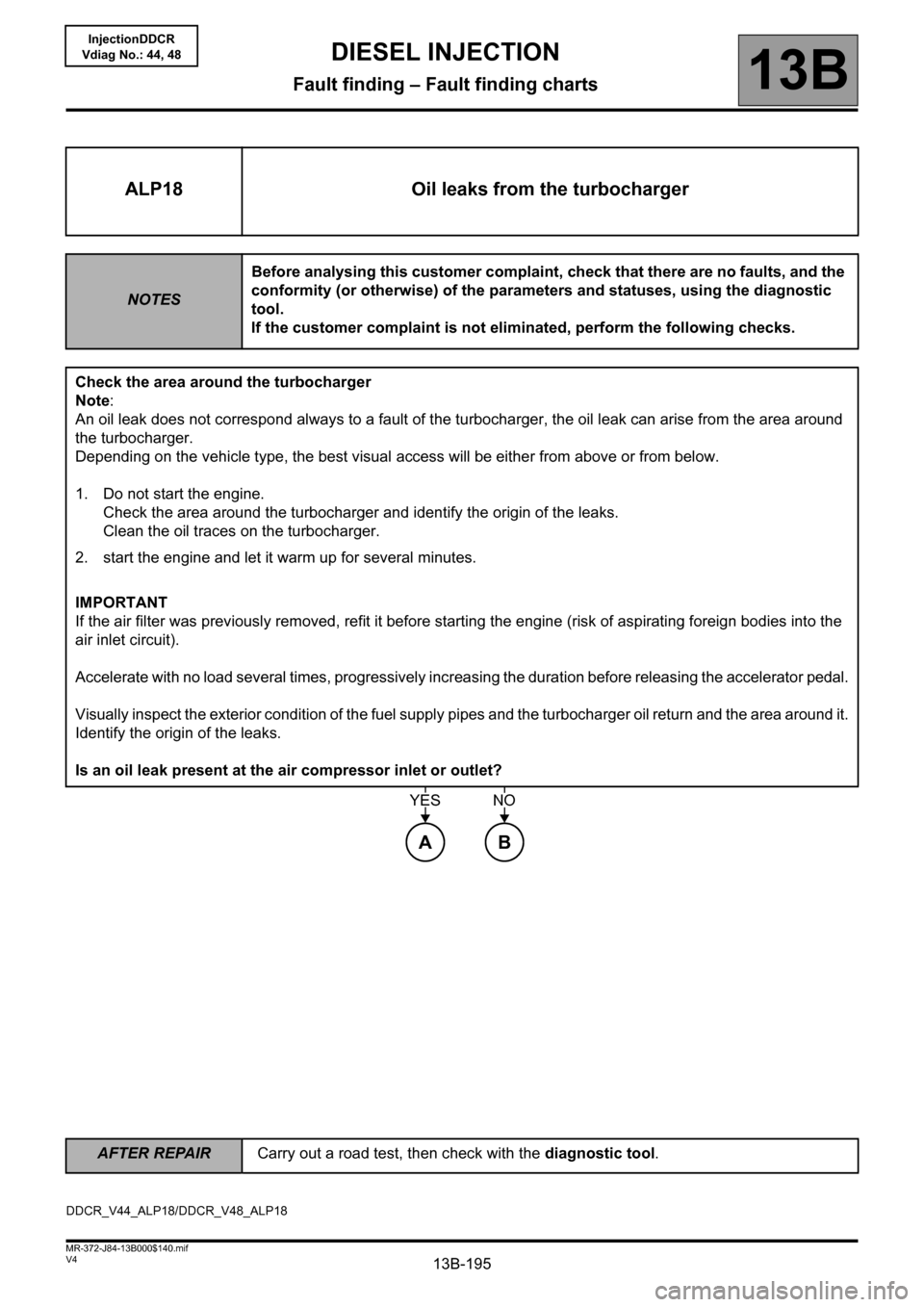
ALP18 Oil leaks from the turbocharger
NOTESBefore analysing this customer complaint, check that there are no faults, and the
conformity (or otherwise) of the parameters and statuses, using the diagnostic
tool.
If the customer complaint is not eliminated, perform the following checks.
Check the area around the turbocharger
Note:
An oil leak does not correspond always to a fault of the turbocharger, the oil leak can arise from the area around
the turbocharger.
Depending on the vehicle type, the best visual access will be either from above or from below.
1. Do not start the engine.
Check the area around the turbocharger and identify the origin of the leaks.
Clean the oil traces on the turbocharger.
2. start the engine and let it warm up for several minutes.
IMPORTANT
If the air filter was previously removed, refit it before starting the engine (risk of aspirating foreign bodies into the
air inlet circuit).
Accelerate with no load several times, progressively increasing the duration before releasing the accelerator pedal.
Visually inspect the exterior condition of the fuel supply pipes and the turbocharger oil return and the area around it.
Identify the origin of the leaks.
Is an oil leak present at the air compressor inlet or outlet?
AB
YESNO
DDCR_V44_ALP18/DDCR_V48_ALP18
Page 196 of 198
13B-196
AFTER REPAIRCarry out a road test, then check with the diagnostic tool.
V4 MR-372-J84-13B000$140.mif
DIESEL INJECTION
Fault finding – Fault finding charts13B
InjectionDDCR
Vdiag No.: 44, 48
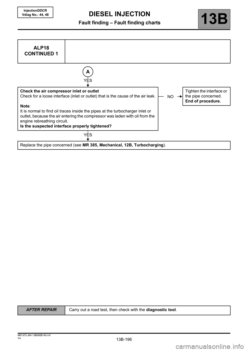
ALP18
CONTINUED 1
Check the air compressor inlet or outlet
Check for a loose interface (inlet or outlet) that is the cause of the air leak.
Note:
It is normal to find oil traces inside the pipes at the turbocharger inlet or
outlet, because the air entering the compressor was laden with oil from the
engine rebreathing circuit.
Is the suspected interface properly tightened?Tighten the interface or
the pipe concerned.
End of procedure.
Replace the pipe concerned (see MR 385, Mechanical, 12B, Turbocharging).
A
YES
NO
YES