rack RENAULT SCENIC 2011 J95 / 3.G Engine And Peripherals Workshop Manual
[x] Cancel search | Manufacturer: RENAULT, Model Year: 2011, Model line: SCENIC, Model: RENAULT SCENIC 2011 J95 / 3.GPages: 198, PDF Size: 0.85 MB
Page 2 of 198

13B-2V4 MR-372-J84-13B000$010.mif
13B
DDCR INJECTION
Vdiag No.: 44, 48
1. APPLICABILITY OF THE DOCUMENT
This document presents the fault finding procedure applicable to all computers with the following specifications:
Following the introduction of the Pump repriming function on K9K engines, a new Vdiag was issued to cover this
function.
When replacing a high pressure pump on vehicles fitted with a computer with Vdiag 44, it is essential to reprogram
the injection computer to activate the Pump repriming function.
After reprogramming, Vdiag 44 is replaced by Vdiag 48.
2. PREREQUISITES FOR FAULT FINDING:
Documentation type:
Fault finding procedures (this document):
– Assisted fault finding (integrated into the diagnostic tool), Dialogys.
Wiring Diagrams:
– Visu-Schéma (CD-ROM), paper.
Type of diagnostic tools:
–CLIP
Special tooling required:
3. REMINDERS
Procedure
To run fault finding on the vehicle's computers, switch on the ignition in fault finding mode (forced + after ignition
feed).
Proceed as follows:
– Vehicle card in card reader.
– Press and hold the start button (longer than 5 seconds) with the start-up conditions not fulfilled.
– Then connect the diagnostic tool and perform the required operations.Vehicle(s): MEGANE II, SCENIC II
for engines K9K 722, 728, 729
Function concerned: DELPHI K9 DIESEL
DIRECT COMMON RAIL INJECTION (DDCR)Computer name: DDCR INJECTION
Program No.: BE
Vdiag No.: 44, 48
SPECIAL TOOLING REQUIRED
Multimeter.
Elé. 1590 112-track computer bornier.
Elé. 1681 Universal bornier.
Mot. 1711 Injector flow measuring kit.
DDCR_V44_PRELI/DDCR_V48_PRELI
DIESEL INJECTION
Fault finding – Introduction
Page 5 of 198
13B-5V4 MR-372-J84-13B000$010.mif
DIESEL INJECTION
Fault finding – Introduction13B
DDCR INJECTION
Vdiag No.: 44, 48
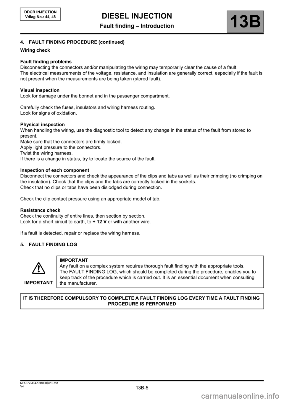
4. FAULT FINDING PROCEDURE (continued)
Wiring check
Fault finding problems
Disconnecting the connectors and/or manipulating the wiring may temporarily clear the cause of a fault.
The electrical measurements of the voltage, resistance, and insulation are generally correct, especially if the fault is
not present when the measurements are being taken (stored fault).
Visual inspection
Look for damage under the bonnet and in the passenger compartment.
Carefully check the fuses, insulators and wiring harness routing.
Look for signs of oxidation.
Physical inspection
When handling the wiring, use the diagnostic tool to detect any change in the status of the fault from stored to
present.
Make sure that the connectors are firmly locked.
Apply light pressure to the connectors.
Twist the wiring harness.
If there is a change in status, try to locate the source of the fault.
Inspection of each component
Disconnect the connectors and check the appearance of the clips and tabs as well as their crimping (no crimping on
the insulation). Check that the clips and the tabs are correctly locked in the sockets.
Check that no clips or tabs have been dislodged during connection.
Check the clip contact pressure using an appropriate model of tab.
Resistance check
Check the continuity of entire lines, then section by section.
Look for a short circuit to earth, to + 12 V or with another wire.
If a fault is detected, repair or replace the wiring harness.
5. FAULT FINDING LOG
IMPORTANTIMPORTANT
Any fault on a complex system requires thorough fault finding with the appropriate tools.
The FAULT FINDING LOG, which should be completed during the procedure, enables you to
keep track of the procedure which is carried out. It is an essential document when consulting
the manufacturer.
IT IS THEREFORE COMPULSORY TO COMPLETE A FAULT FINDING LOG EVERY TIME A FAULT FINDING
PROCEDURE IS PERFORMED
Page 15 of 198

13B-15V4 MR-372-J84-13B000$020.mif
DIESEL INJECTION
Fault finding – System operation13B
DDCR INJECTION
Vdiag No.: 44, 48
32-TRACK BLACK CONNECTOR A
Description Tracks Tracks Description
Not used A1 E1 Not used
Cruise control On/Off A2 E2 Not used
CAN L1 A3 E3 Not used
CAN H1 A4 E4 Closed contact Stop signal
Not used B1 F1 Not used
Not used B2 F2 Potentiometer supply Gang 2
Not used B3 F3 Potentiometer signal Gang 2
Diagnostic line K B4 F4 Potentiometer earth Gang 2
Not used C1 G1+After ignition supply
Not used C2 G2 Potentiometer supply Gang 1
Speed limiter on/off C3 G3 Not used
Clutch switch information C4 G4 Earth
+After ignition supply D1 H1 Earth
Cruise control switch signal D2H2 Potentiometer signal Gang 1
Cruise control switch earth D3H3 Potentiometer earth Gang 1
Not used D4 H4 Earth
NOTE:
The supply voltage on track G1 is not measurable when the computer connector is disconnected.
Page 16 of 198

13B-16V4 MR-372-J84-13B000$020.mif
DIESEL INJECTION
Fault finding – System operation13B
DDCR INJECTION
Vdiag No.: 44, 48
48-TRACK BROWN CONNECTOR B
Description Tracks Tracks Description
Flowmeter supply (728, 729) A1 G1 Knock sensor earth (pinking)
Flowmeter signal (728, 729) A2 G2 Fuel temperature signal
Flowmeter earth (728, 729) A3 G3 Fuel temperature sensor earth
Cylinder 1 injector + control A4 G4 Cylinder 4 injector + control
EGR feedback potentiometer supply B1 H1 Not used
EGR feedback potentiometer signal B2 H2 Coolant temperature signal
EGR feedback potentiometer earth B3 H3 Coolant temperature sensor earth
Cylinder 1 injector - control B4 H4 Cylinder 4 injector - control
Turbocharging pressure sensor supply C1 J1 Not used
Turbocharging pressure sensor signal C2 J2 Inlet air temperature signal
Turbocharging pressure sensor earth C3 J3 Inlet air temperature earth (722)
Cylinder 2 injector + control C4 J4 Not used
Rail pressure sensor supply D1 K1 Accelerometer shielding (pinking)
Rail pressure sensor signal D2 K2 External air temperature signal
Rail pressure sensor earth D3 K3 External air temperature earth
Cylinder 2 injector - control D4 K4 Not used
Not used E1 L1 Not used
Phase sensor signal (cylinder) E2 L2 Not used
Phase sensor earth (cylinder) E3 L3 EGR valve control
Cylinder 3 injector + control E4 L4 Not used
Knock sensor signal (pinking) F1 M1 Not used
Engine speed (TDC) sensor + signal F2 M2Turbocharging solenoid valve control
(728, 729)
Engine speed sensor earth (TDC) F3 M3 Not used
Cylinder 3 injector - control F4 M4 Fuel flow actuator control
Page 17 of 198

13B-17V4 MR-372-J84-13B000$020.mif
DIESEL INJECTION
Fault finding – System operation13B
DDCR INJECTION
Vdiag No.: 44, 48
32-TRACK GREY CONNECTOR C
Description Tracks Tracks Description
Not used A1 E1 Not used
Water in diesel fuel detector earth A2 E2 Not used
Not used A3 E3 Not used
Not used A4 E4 Not used
Not used B1 F1 Supply relay control
Not used B2 F2 Preheating relay control
Water in diesel fuel detector signal B3 F3 Not used
Not used B4 F4 Not used
Not used C1 G1 Not used
Not used C2 G2 After relay + battery 1 earth
Refrigerant pressure sensor signal C3 G3 Refrigerant pressure sensor earth
Refrigerant pressure sensor supply C4 G4 Not used
Not used D1 H1 Potentiometer earth Gang 1
Not used D2 H2 Not used
Heater plug diag signal D3 H3 After relay + battery 2
Not used D4 H4 Not used
NOTE:
The supply voltage on tracks G2 and H2 is not measurable when the computer connector is disconnected.
Page 22 of 198

13B-22V4 MR-372-J84-13B000$050.mif
13B
DDCR INJECTION
Vdiag No.: 44, 48
Tool faultAssociated
DTCDiagnostic tool title
DF001 0115 Coolant temperature sensor circuit
DF002 0070 Air temperature sensor circuit (728, 729)
DF003 2226 Atmospheric pressure sensor circuit
DF005 0335 Engine speed sensor circuit.
DF007 0190 Rail pressure sensor circuit
DF008 0225 Pedal potentiometer circuit track 1
DF009 2120 Pedal potentiometer circuit track 2
DF010 0409 EGR position sensor circuit
DF014 0500 Vehicle speed information circuit
DF015 0685 Main relay control circuit
DF016 0403 EGR control circuit
DF017 0382 Preheating unit control circuit
DF024 0231 Low pressure actuator control circuit
DF025 0380 Preheater unit diagnostic connection
DF026 0201 Cylinder 1 injector control circuit
DF027 0202 Cylinder 2 injector control circuit
DF028 0203 Cylinder 3 injector control circuit
DF029 0204 Cylinder 4 injector control circuit
DF037 0513 Engine immobiliser
DF038 0606 Computer
DF039 0110 Inlet air temperature sensor circuit
DF047 0560 Computer feed voltage
DIESEL INJECTION
Fault finding – Fault summary table
Page 24 of 198
13B-24
AFTER REPAIRDeal with any faults displayed by the diagnostic tool. Clear the computer fault memory.
Carry out a road test followed by another check with the diagnostic tool.
V4 MR-372-J84-13B000$061.mif
13B
DDCR INJECTION
Vdiag No.: 44, 48
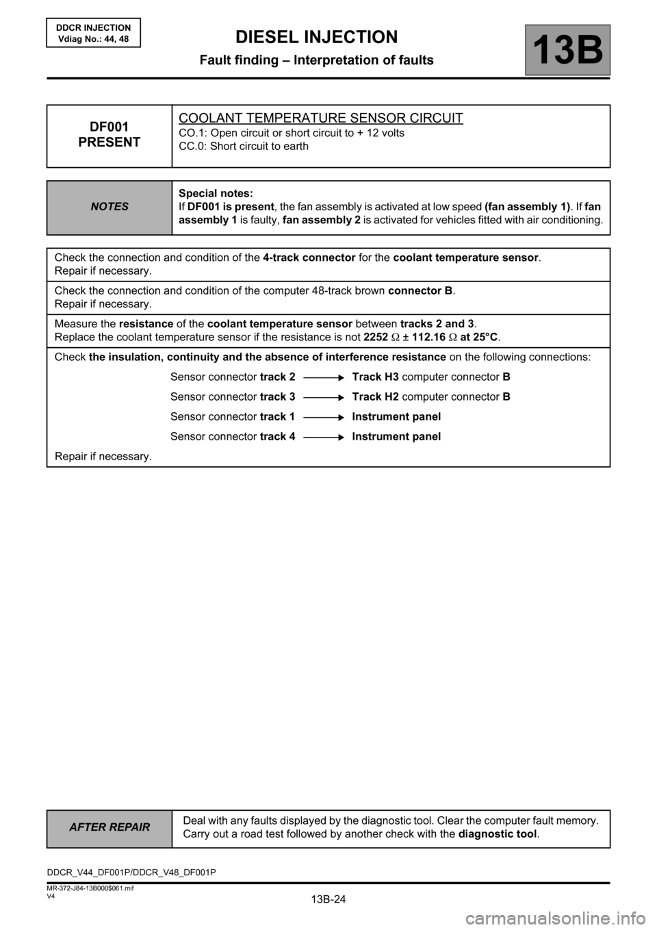
DF001
PRESENTCOOLANT TEMPERATURE SENSOR CIRCUITCO.1: Open circuit or short circuit to + 12 volts
CC.0: Short circuit to earth
NOTESSpecial notes:
If DF001 is present, the fan assembly is activated at low speed (fan assembly 1). If fan
assembly 1 is faulty, fan assembly 2 is activated for vehicles fitted with air conditioning.
Check the connection and condition of the 4-track connector for the coolant temperature sensor.
Repair if necessary.
Check the connection and condition of the computer 48-track brown connector B.
Repair if necessary.
Measure the resistance of the coolant temperature sensor between tracks 2 and 3.
Replace the coolant temperature sensor if the resistance is not 2252 Ω ± 112.16 Ω at 25°C.
Check the insulation, continuity and the absence of interference resistance on the following connections:
Sensor connector track 2 Track H3 computer connector B
Sensor connector track 3 Track H2 computer connector B
Sensor connector track 1 Instrument panel
Sensor connector track 4 Instrument panel
Repair if necessary.
DDCR_V44_DF001P/DDCR_V48_DF001P
DIESEL INJECTION
Fault finding – Interpretation of faults
Page 25 of 198
13B-25
AFTER REPAIRDeal with any faults displayed by the diagnostic tool. Clear the computer fault memory.
Carry out a road test followed by another check with the diagnostic tool.
V4 MR-372-J84-13B000$061.mif
DIESEL INJECTION
Fault finding – Interpretation of faults13B
DDCR INJECTION
Vdiag No.: 44, 48
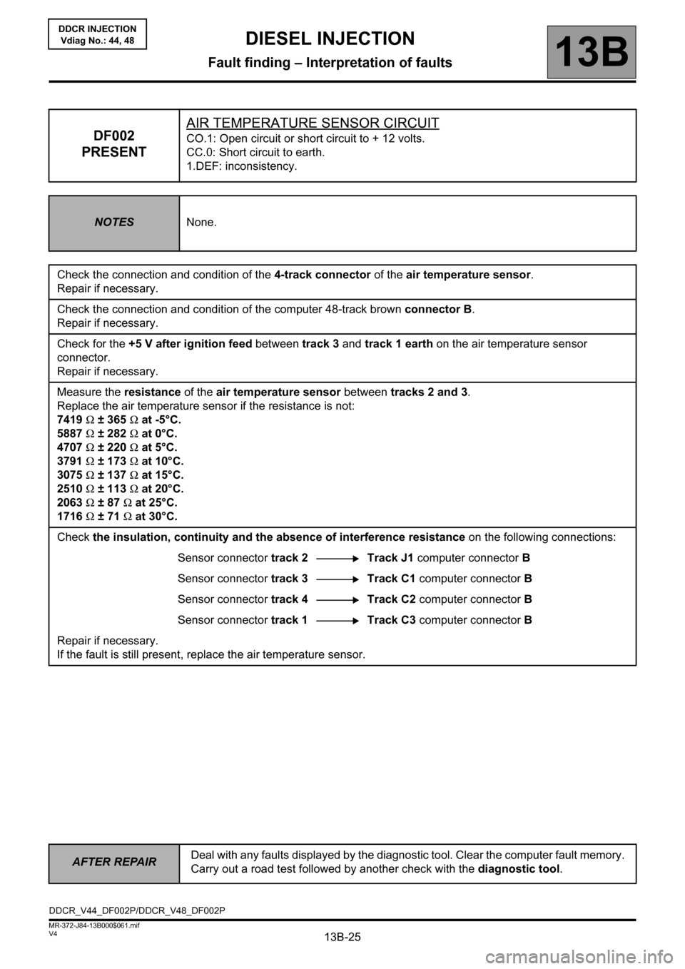
DF002
PRESENTAIR TEMPERATURE SENSOR CIRCUITCO.1: Open circuit or short circuit to + 12 volts.
CC.0: Short circuit to earth.
1.DEF: inconsistency.
NOTESNone.
Check the connection and condition of the 4-track connector of the air temperature sensor.
Repair if necessary.
Check the connection and condition of the computer 48-track brown connector B.
Repair if necessary.
Check for the +5 V after ignition feed between track 3 and track 1 earth on the air temperature sensor
connector.
Repair if necessary.
Measure the resistance of the air temperature sensor between tracks 2 and 3.
Replace the air temperature sensor if the resistance is not:
7419 Ω ± 365 Ω at -5°C.
5887 Ω ± 282 Ω at 0°C.
4707 Ω ± 220 Ω at 5°C.
3791 Ω ± 173 Ω at 10°C.
3075 Ω ± 137 Ω at 15°C.
2510 Ω ± 113 Ω at 20°C.
2063 Ω ± 87 Ω at 25°C.
1716 Ω ± 71 Ω at 30°C.
Check the insulation, continuity and the absence of interference resistance on the following connections:
Sensor connector track 2 Track J1 computer connector B
Sensor connector track 3 Track C1 computer connector B
Sensor connector track 4 Track C2 computer connector B
Sensor connector track 1 Track C3 computer connector B
Repair if necessary.
If the fault is still present, replace the air temperature sensor.
DDCR_V44_DF002P/DDCR_V48_DF002P
Page 27 of 198
13B-27
AFTER REPAIRDeal with any faults displayed by the diagnostic tool. Clear the computer fault memory.
Carry out a road test followed by another check with the diagnostic tool.
V4 MR-372-J84-13B000$061.mif
DIESEL INJECTION
Fault finding – Interpretation of faults13B
DDCR INJECTION
Vdiag No.: 44, 48
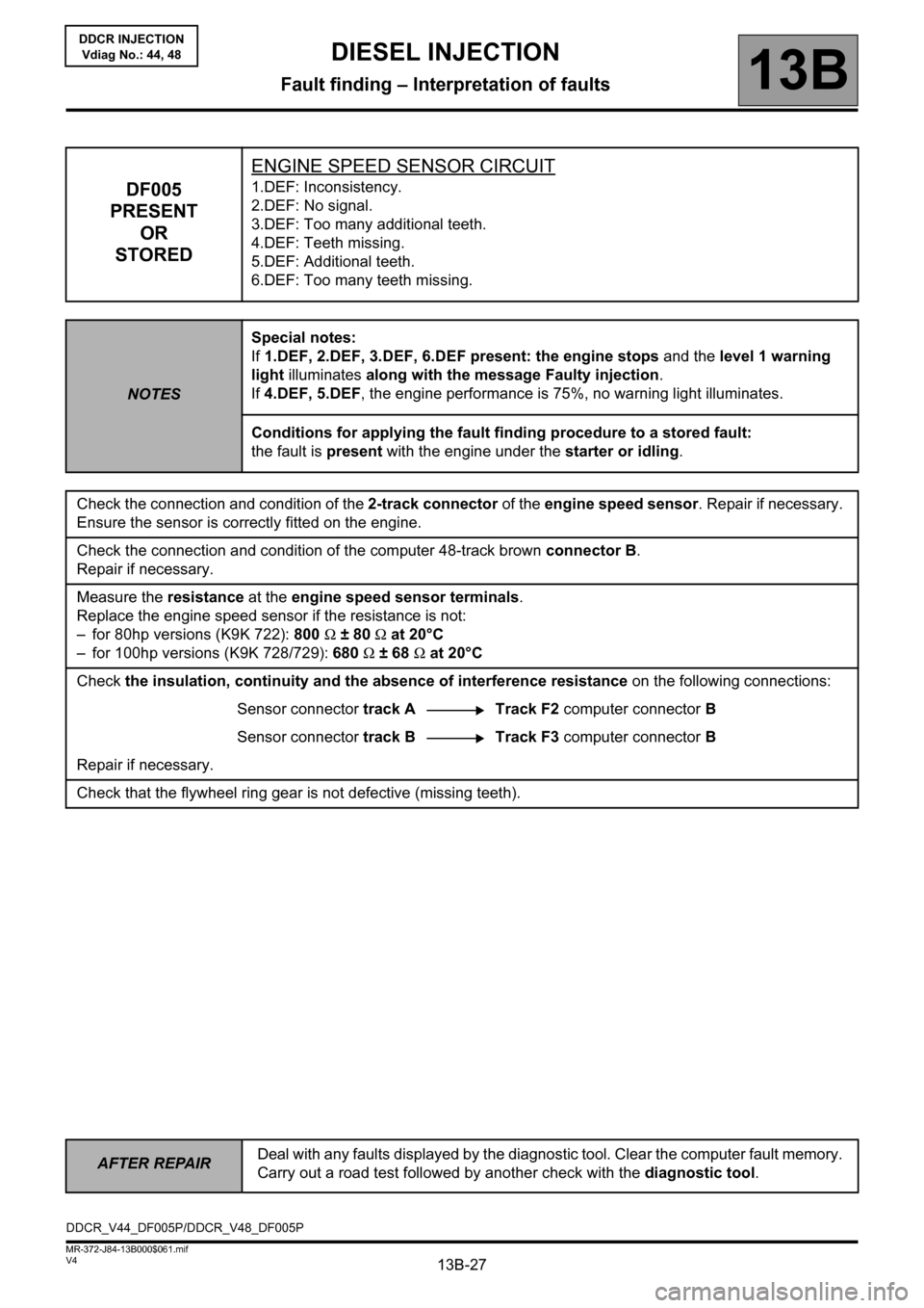
DF005
PRESENT
OR
STOREDENGINE SPEED SENSOR CIRCUIT1.DEF: Inconsistency.
2.DEF: No signal.
3.DEF: Too many additional teeth.
4.DEF: Teeth missing.
5.DEF: Additional teeth.
6.DEF: Too many teeth missing.
NOTESSpecial notes:
If 1.DEF, 2.DEF, 3.DEF, 6.DEF present: the engine stops and the level 1 warning
light illuminates along with the message Faulty injection.
If 4.DEF, 5.DEF, the engine performance is 75%, no warning light illuminates.
Conditions for applying the fault finding procedure to a stored fault:
the fault is present with the engine under the starter or idling.
Check the connection and condition of the 2-track connector of the engine speed sensor. Repair if necessary.
Ensure the sensor is correctly fitted on the engine.
Check the connection and condition of the computer 48-track brown connector B.
Repair if necessary.
Measure the resistance at the engine speed sensor terminals.
Replace the engine speed sensor if the resistance is not:
– for 80hp versions (K9K 722): 800 Ω ± 80 Ω at 20°C
– for 100hp versions (K9K 728/729): 680 Ω ± 68 Ω at 20°C
Check the insulation, continuity and the absence of interference resistance on the following connections:
Sensor connector track A Track F2 computer connector B
Sensor connector track BTrack F3 computer connector B
Repair if necessary.
Check that the flywheel ring gear is not defective (missing teeth).
DDCR_V44_DF005P/DDCR_V48_DF005P
Page 28 of 198
13B-28
AFTER REPAIRDeal with any faults displayed by the diagnostic tool. Clear the computer fault memory.
Carry out a road test followed by another check with the diagnostic tool.
V4 MR-372-J84-13B000$061.mif
DIESEL INJECTION
Fault finding – Interpretation of faults13B
DDCR INJECTION
Vdiag No.: 44, 48
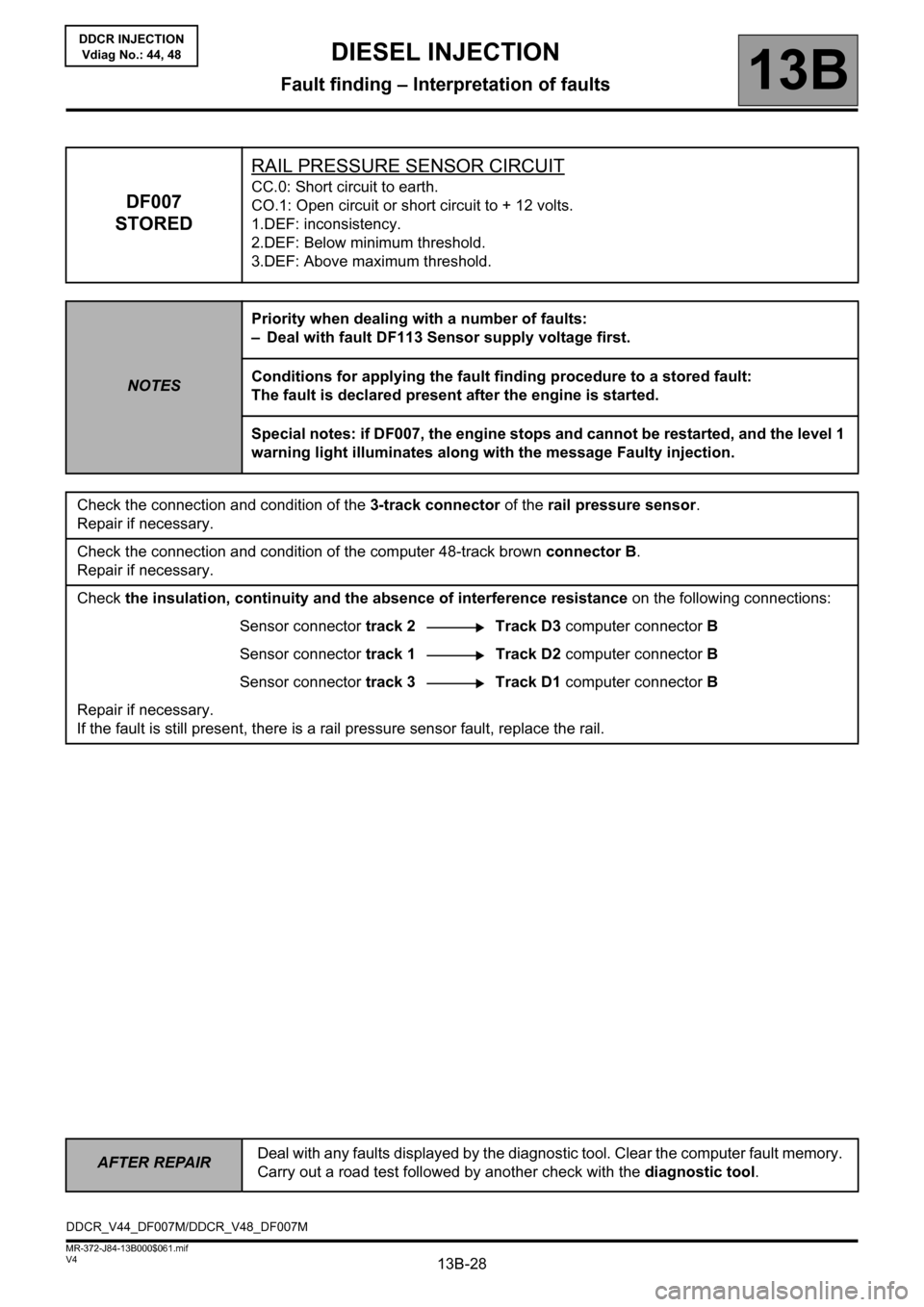
DF007
STOREDRAIL PRESSURE SENSOR CIRCUIT
CC.0: Short circuit to earth.
CO.1: Open circuit or short circuit to + 12 volts.
1.DEF: inconsistency.
2.DEF: Below minimum threshold.
3.DEF: Above maximum threshold.
NOTESPriority when dealing with a number of faults:
– Deal with fault DF113 Sensor supply voltage first.
Conditions for applying the fault finding procedure to a stored fault:
The fault is declared present after the engine is started.
Special notes: if DF007, the engine stops and cannot be restarted, and the level 1
warning light illuminates along with the message Faulty injection.
Check the connection and condition of the 3-track connector of the rail pressure sensor.
Repair if necessary.
Check the connection and condition of the computer 48-track brown connector B.
Repair if necessary.
Check the insulation, continuity and the absence of interference resistance on the following connections:
Sensor connector track 2 Track D3 computer connector B
Sensor connector track 1Track D2 computer connector B
Sensor connector track 3 Track D1 computer connector B
Repair if necessary.
If the fault is still present, there is a rail pressure sensor fault, replace the rail.
DDCR_V44_DF007M/DDCR_V48_DF007M