relay RENAULT SCENIC 2011 J95 / 3.G Engine And Peripherals Workshop Manual
[x] Cancel search | Manufacturer: RENAULT, Model Year: 2011, Model line: SCENIC, Model: RENAULT SCENIC 2011 J95 / 3.GPages: 198, PDF Size: 0.85 MB
Page 11 of 198

13B-11V4 MR-372-J84-13B000$020.mif
DIESEL INJECTION
Fault finding – System operation13B
DDCR INJECTION
Vdiag No.: 44, 48
WITH FLOWMETER (K9K 728)
The flow of fresh air entering the engine is given by a hot wire ratiometric sensor. This flow sensor is used to
manage the amount of exhaust gas to be recirculated to ensure optimum recirculation rates. A fresh air temperature
sensor is built into the flowmeter.
Air flow measurement allows closed-loop control via the EGR valve.
Besides electrical faults with the sensor, there is a consistency test between the measured air flow and an estimated
air flow without EGR.
This flow evaluates the amount of fresh inlet air, based on the values supplied by the surrounding systems:
– the inlet air temperature measured by a sensor located after the turbocharger and/or after the intercooler (if fitted),
– the turbocharging pressure,
– the engine speed.
Pre-postheating actuation
Pre-postheating actuation consists of controlling the heater plugs and preheating warning light on the instrument
panel. The heater plugs are activated by relays, and the power is supplied from the battery. After the ignition is
switched on. Preheating is activated for a period of time. The warning light is illuminated for an activation period that
depends on the battery voltage, the atmospheric pressure, and the coolant temperature. When the temperature is
below a certain threshold, a postheating function can be used to improve the combustion stability, and consequently
engine operation (reducing unburnt particles and pollutant emissions).
Turbocharger control solenoid valve actuation
The turbocharger system comprises a solenoid valve that is used to actuate the vanes (or wastegate) to create an
overpressure or a vacuum in the inlet circuit.
Page 17 of 198

13B-17V4 MR-372-J84-13B000$020.mif
DIESEL INJECTION
Fault finding – System operation13B
DDCR INJECTION
Vdiag No.: 44, 48
32-TRACK GREY CONNECTOR C
Description Tracks Tracks Description
Not used A1 E1 Not used
Water in diesel fuel detector earth A2 E2 Not used
Not used A3 E3 Not used
Not used A4 E4 Not used
Not used B1 F1 Supply relay control
Not used B2 F2 Preheating relay control
Water in diesel fuel detector signal B3 F3 Not used
Not used B4 F4 Not used
Not used C1 G1 Not used
Not used C2 G2 After relay + battery 1 earth
Refrigerant pressure sensor signal C3 G3 Refrigerant pressure sensor earth
Refrigerant pressure sensor supply C4 G4 Not used
Not used D1 H1 Potentiometer earth Gang 1
Not used D2 H2 Not used
Heater plug diag signal D3 H3 After relay + battery 2
Not used D4 H4 Not used
NOTE:
The supply voltage on tracks G2 and H2 is not measurable when the computer connector is disconnected.
Page 22 of 198

13B-22V4 MR-372-J84-13B000$050.mif
13B
DDCR INJECTION
Vdiag No.: 44, 48
Tool faultAssociated
DTCDiagnostic tool title
DF001 0115 Coolant temperature sensor circuit
DF002 0070 Air temperature sensor circuit (728, 729)
DF003 2226 Atmospheric pressure sensor circuit
DF005 0335 Engine speed sensor circuit.
DF007 0190 Rail pressure sensor circuit
DF008 0225 Pedal potentiometer circuit track 1
DF009 2120 Pedal potentiometer circuit track 2
DF010 0409 EGR position sensor circuit
DF014 0500 Vehicle speed information circuit
DF015 0685 Main relay control circuit
DF016 0403 EGR control circuit
DF017 0382 Preheating unit control circuit
DF024 0231 Low pressure actuator control circuit
DF025 0380 Preheater unit diagnostic connection
DF026 0201 Cylinder 1 injector control circuit
DF027 0202 Cylinder 2 injector control circuit
DF028 0203 Cylinder 3 injector control circuit
DF029 0204 Cylinder 4 injector control circuit
DF037 0513 Engine immobiliser
DF038 0606 Computer
DF039 0110 Inlet air temperature sensor circuit
DF047 0560 Computer feed voltage
DIESEL INJECTION
Fault finding – Fault summary table
Page 35 of 198

13B-35
AFTER REPAIRDeal with any faults displayed by the diagnostic tool. Clear the computer fault memory.
Carry out a road test followed by another check with the diagnostic tool.
V4 MR-372-J84-13B000$061.mif
DIESEL INJECTION
Fault finding – Interpretation of faults13B
DDCR INJECTION
Vdiag No.: 44, 48
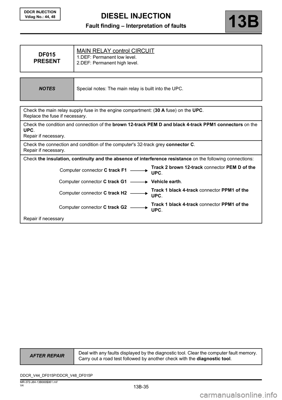
DF015
PRESENTMAIN RELAY control CIRCUIT1.DEF: Permanent low level.
2.DEF: Permanent high level.
NOTESSpecial notes: The main relay is built into the UPC.
Check the main relay supply fuse in the engine compartment: (30 A fuse) on the UPC.
Replace the fuse if necessary.
Check the condition and connection of the brown 12-track PEM D and black 4-track PPM1 connectors on the
UPC.
Repair if necessary.
Check the connection and condition of the computer's 32-track grey connector C.
Repair if necessary.
Check the insulation, continuity and the absence of interference resistance on the following connections:
Computer connector C track F1Track 2 brown 12-track connector PEM D of the
UPC.
Computer connector C track G1 Vehicle earth.
Computer connector C track H2Track 1 black 4-track connector PPM1 of the
UPC.
Computer connector C track G2Track 1 black 4-track connector PPM1 of the
UPC.
Repair if necessary
DDCR_V44_DF015P/DDCR_V48_DF015P
Page 87 of 198

13B-87V4 MR-372-J84-13B000$070.mif
DIESEL INJECTION
Fault finding – Conformity check13B
DDCR INJECTION
Vdiag No.: 44, 48
STARTING SUB-FUNCTION:
NOTESOnly check conformity after a full check with the diagnostic tool.
The values shown in this conformity check are given as examples.
Application conditions: Engine off, ignition on.
FunctionParameter or Status
Check or actionDisplay and notes Fault finding
+ After ignition
computer feedET001: + After ignition
computer feed.
PRESENTIndicates + after ignition feed to
the computer.
- Present
- AbsentIn the event of a fault, apply
the fault finding procedure for
DF047 "Computer feed
voltage" or DF015 "Main relay
control circuit".
StartingET076: Starting.
AUTHORISEDIndicates whether or not
starting has been authorised by
the injection.
AUTHORISED: The injection
authorises starting.
PROHIBITED: The injection
does not authorise starting.If PROHIBITED, carry out
a complete fault finding
procedure on the preheating
system.
EngineET038: Engine.
UNDER + AFTER
IGNITION FEEDIndicates the current status of
the engine.
- UNDER + AFTER IGNITION
FEED
- UNDER STARTER
- RUNNING
- SUPPLY MAINTAINED: Supply
maintained during the power
latch phase.
- STALLED: When the engine
has stalled.
- PROTECTED: When a fault has
appeared or when the engine
speed is locked at a certain
value.NONE
Battery
voltagePR074: Battery
voltage.12 V < PR074 < 13.5 VIf there is a fault, apply the
fault finding procedure for
the "Charge circuit".
Page 107 of 198

13B-107V4 MR-372-J84-13B000$070.mif
DIESEL INJECTION
Fault finding – Conformity check13B
DDCR INJECTION
Vdiag No.: 44, 48
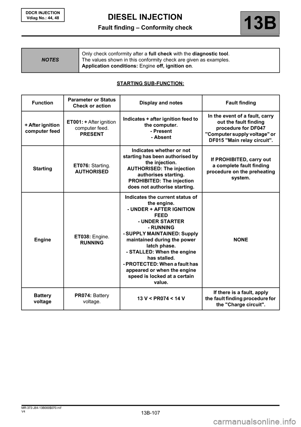
STARTING SUB-FUNCTION:
NOTESOnly check conformity after a full check with the diagnostic tool.
The values shown in this conformity check are given as examples.
Application conditions: Engine off, ignition on.
FunctionParameter or Status
Check or actionDisplay and notes Fault finding
+ After ignition
computer feedET001: + After ignition
computer feed.
PRESENTIndicates + after ignition feed to
the computer.
- Present
- AbsentIn the event of a fault, carry
out the fault finding
procedure for DF047
"Computer supply voltage" or
DF015 "Main relay circuit".
StartingET076: Starting.
AUTHORISEDIndicates whether or not
starting has been authorised by
the injection.
AUTHORISED: The injection
authorises starting.
PROHIBITED: The injection
does not authorise starting.If PROHIBITED, carry out
a complete fault finding
procedure on the preheating
system.
EngineET038: Engine.
RUNNINGIndicates the current status of
the engine.
- UNDER + AFTER IGNITION
FEED
- UNDER STARTER
- RUNNING
- SUPPLY MAINTAINED: Supply
maintained during the power
latch phase.
- STALLED: When the engine
has stalled.
- PROTECTED: When a fault has
appeared or when the engine
speed is locked at a certain
value.NONE
Battery
voltagePR074: Battery
voltage.13 V < PR074 < 14 VIf there is a fault, apply
the fault finding procedure for
the "Charge circuit".
Page 149 of 198

13B-149V4 MR-372-J84-13B000$120.mif
DIESEL INJECTION
Fault finding – Tests13B
DDCR INJECTION
Vdiag No.: 44, 48
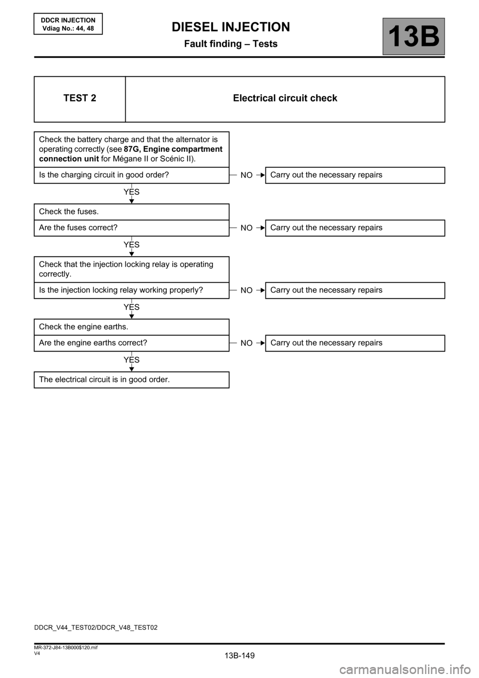
TEST 2 Electrical circuit check
Check the battery charge and that the alternator is
operating correctly (see 87G, Engine compartment
connection unit for Mégane II or Scénic II).
Is the charging circuit in good order? Carry out the necessary repairs
Check the fuses.
Are the fuses correct? Carry out the necessary repairs
Check that the injection locking relay is operating
correctly.
Is the injection locking relay working properly? Carry out the necessary repairs
Check the engine earths.
Are the engine earths correct?Carry out the necessary repairs
The electrical circuit is in good order.
NO
YES
NO
YES
NO
YES
NO
YES
DDCR_V44_TEST02/DDCR_V48_TEST02