fuel filter RENAULT SCENIC 2012 J95 / 3.G Engine And Peripherals EDC16CP33 User Guide
[x] Cancel search | Manufacturer: RENAULT, Model Year: 2012, Model line: SCENIC, Model: RENAULT SCENIC 2012 J95 / 3.GPages: 510, PDF Size: 2.98 MB
Page 325 of 510
13B-325V12 MR-372-J84-13B300$110.mif
13B
EDC16CP33
Program No.: C4
VDiag No.: 04, 08, 18, 1C,
20, 24, 26, 28, 34, 38, 44,
4C, 54, 58, 5C, 60, 62, 74
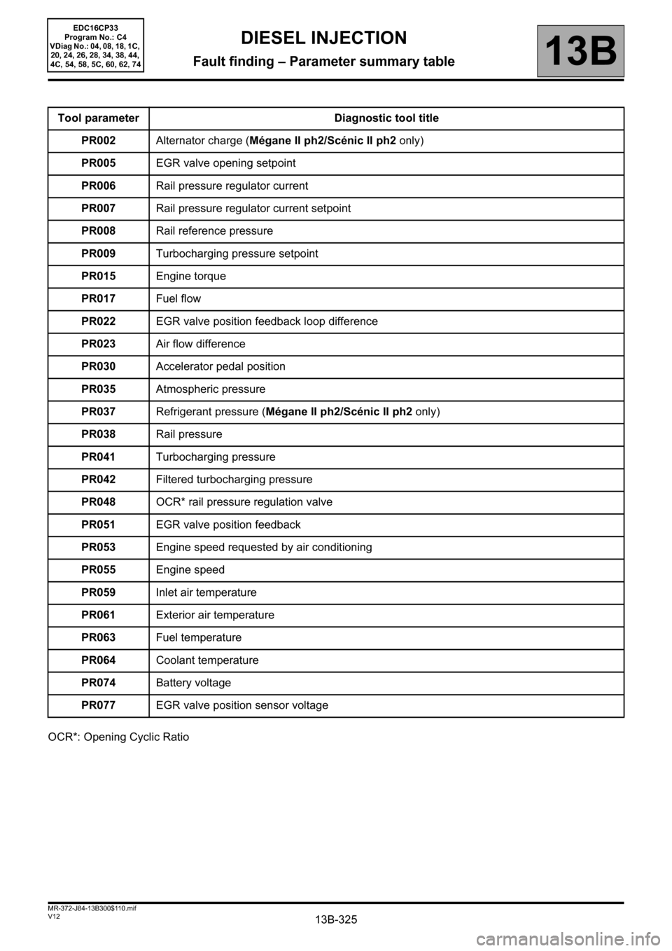
OCR*: Opening Cyclic RatioTool parameter Diagnostic tool title
PR002Alternator charge (Mégane II ph2/Scénic II ph2 only)
PR005EGR valve opening setpoint
PR006Rail pressure regulator current
PR007Rail pressure regulator current setpoint
PR008Rail reference pressure
PR009Turbocharging pressure setpoint
PR015Engine torque
PR017Fuel flow
PR022EGR valve position feedback loop difference
PR023Air flow difference
PR030Accelerator pedal position
PR035Atmospheric pressure
PR037Refrigerant pressure (Mégane II ph2/Scénic II ph2 only)
PR038Rail pressure
PR041Turbocharging pressure
PR042Filtered turbocharging pressure
PR048OCR* rail pressure regulation valve
PR051EGR valve position feedback
PR053Engine speed requested by air conditioning
PR055Engine speed
PR059Inlet air temperature
PR061Exterior air temperature
PR063Fuel temperature
PR064Coolant temperature
PR074Battery voltage
PR077EGR valve position sensor voltage
DIESEL INJECTION
Fault finding – Parameter summary table
Page 326 of 510
13B-326V12 MR-372-J84-13B300$110.mif
DIESEL INJECTION
Fault finding – Parameter summary table13B
EDC16CP33
Program No.: C4
VDiag No.: 04, 08, 18, 1C,
20, 24, 26, 28, 34, 38, 44,
4C, 54, 58, 5C, 60, 62, 74
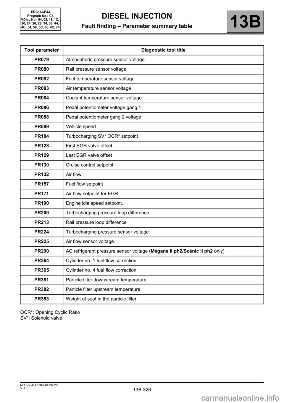
OCR*: Opening Cyclic Ratio
SV*: Solenoid valveTool parameter Diagnostic tool title
PR079Atmospheric pressure sensor voltage
PR080Rail pressure sensor voltage
PR082Fuel temperature sensor voltage
PR083Air temperature sensor voltage
PR084Coolant temperature sensor voltage
PR086Pedal potentiometer voltage gang 1
PR088Pedal potentiometer gang 2 voltage
PR089Vehicle speed
PR104Turbocharging SV* OCR* setpoint
PR128First EGR valve offset
PR129Last EGR valve offset
PR130Cruise control setpoint
PR132Air flow
PR157Fuel flow setpoint
PR171Air flow setpoint for EGR
PR190Engine idle speed setpoint.
PR209Turbocharging pressure loop difference
PR213Rail pressure loop difference
PR224Turbocharging pressure sensor voltage
PR225Air flow sensor voltage
PR290AC refrigerant pressure sensor voltage (Mégane II ph2/Scénic II ph2 only)
PR364Cylinder no. 1 fuel flow correction
PR365Cylinder no. 4 fuel flow correction
PR381Particle filter downstream temperature
PR382Particle filter upstream temperature
PR383Weight of soot in the particle filter
Page 327 of 510
13B-327V12 MR-372-J84-13B300$110.mif
DIESEL INJECTION
Fault finding – Parameter summary table13B
EDC16CP33
Program No.: C4
VDiag No.: 04, 08, 18, 1C,
20, 24, 26, 28, 34, 38, 44,
4C, 54, 58, 5C, 60, 62, 74
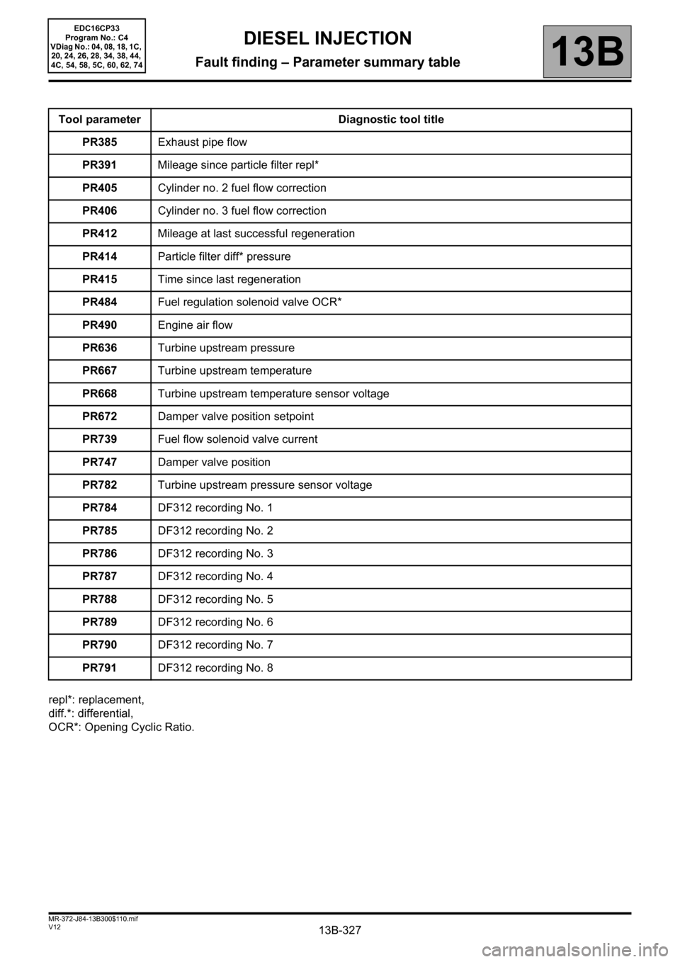
repl*: replacement,
diff.*: differential,
OCR*: Opening Cyclic Ratio.Tool parameter Diagnostic tool title
PR385Exhaust pipe flow
PR391Mileage since particle filter repl*
PR405Cylinder no. 2 fuel flow correction
PR406Cylinder no. 3 fuel flow correction
PR412Mileage at last successful regeneration
PR414Particle filter diff* pressure
PR415Time since last regeneration
PR484Fuel regulation solenoid valve OCR*
PR490Engine air flow
PR636Turbine upstream pressure
PR667Turbine upstream temperature
PR668Turbine upstream temperature sensor voltage
PR672Damper valve position setpoint
PR739Fuel flow solenoid valve current
PR747Damper valve position
PR782Turbine upstream pressure sensor voltage
PR784DF312 recording No. 1
PR785DF312 recording No. 2
PR786DF312 recording No. 3
PR787DF312 recording No. 4
PR788DF312 recording No. 5
PR789DF312 recording No. 6
PR790DF312 recording No. 7
PR791DF312 recording No. 8
Page 422 of 510
13B-422V12 MR-372-J84-13B300$140.mif
13B
EDC16CP33
Program No.: C4
Vdiag No.: 04, 08, 18, 1C,
20, 24, 26, 28, 34, 38, 44,
4C, 54, 58, 5C, 60, 62, 74
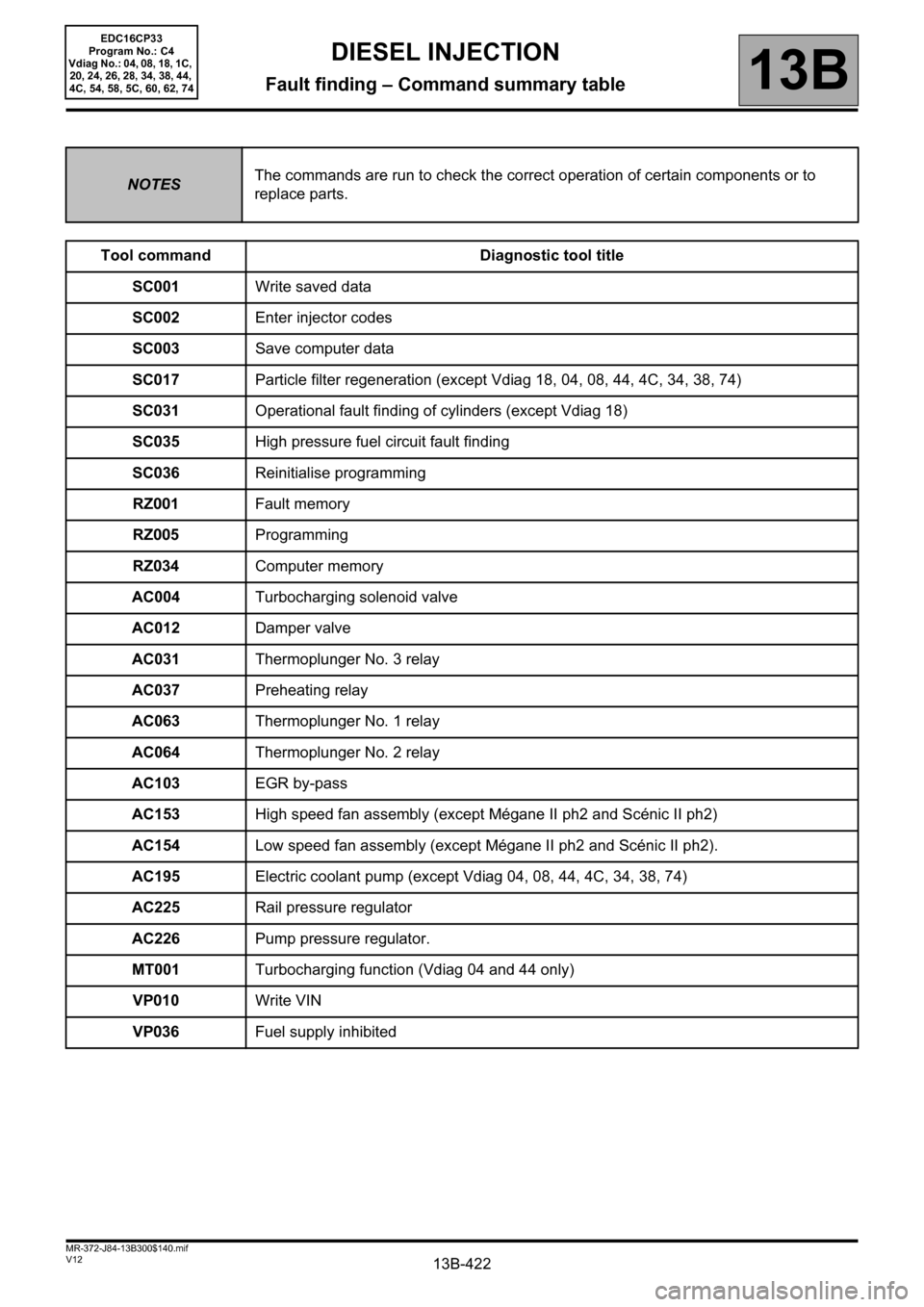
NOTESThe commands are run to check the correct operation of certain components or to
replace parts.
Tool command Diagnostic tool title
SC001Write saved data
SC002Enter injector codes
SC003Save computer data
SC017Particle filter regeneration (except Vdiag 18, 04, 08, 44, 4C, 34, 38, 74)
SC031Operational fault finding of cylinders (except Vdiag 18)
SC035High pressure fuel circuit fault finding
SC036Reinitialise programming
RZ001Fault memory
RZ005Programming
RZ034Computer memory
AC004Turbocharging solenoid valve
AC012Damper valve
AC031Thermoplunger No. 3 relay
AC037Preheating relay
AC063Thermoplunger No. 1 relay
AC064Thermoplunger No. 2 relay
AC103EGR by-pass
AC153High speed fan assembly (except Mégane II ph2 and Scénic II ph2)
AC154Low speed fan assembly (except Mégane II ph2 and Scénic II ph2).
AC195Electric coolant pump (except Vdiag 04, 08, 44, 4C, 34, 38, 74)
AC225Rail pressure regulator
AC226Pump pressure regulator.
MT001Turbocharging function (Vdiag 04 and 44 only)
VP010Write VIN
VP036Fuel supply inhibited
DIESEL INJECTION
Fault finding – Command summary table
Page 434 of 510

13B-434V12 MR-372-J84-13B300$150.mif
DIESEL INJECTION
Fault finding – Interpretation of commands13B
SC035
CONTINUED 1
Interpretation of incorrect results:
– Is one of the value definitions for the various displayed stages is “TOO SLOW” or “TOO FAST”, see the
following table:
STEP X
(X is the variable
from 1 to 4)Rail pressure Raise
timeRail pressure Dump
timeInterpretation of
results
STEP X TOO SLOW TOO SLOW Check 1
STEP X TOO SLOW TOO FAST Check 2
STEP X TOO SLOW OK Check 3
STEP X OK TOO SLOW Check 4
STEP X OK TOO FAST Check 5
STEP 5 TOO FAST Check 5
Explanation of results interpretation:
Check 1:
–Apply Test 10 Poor injector operation.
–Apply ALP6 Fuel circuit leaks.
–Apply Test 3 Low pressure circuit check.
– Replace the high pressure pump.
Check 2:
–Apply Test 10.
–Apply ALP6.
– Apply the part of Test 3 concerning the fuel filter.
– Replace the high pressure pump.
– Check the injector return flow and the injectors.
– Check the rail pressure regulator by running command AC225 Rail pressure regulator.
EDC16CP33
Program No.: C4
Vdiag No.: 04, 08, 18, 1C,
20, 24, 26, 28, 34, 38, 44,
4C, 54, 58, 5C, 60, 62, 74
AFTER REPAIRCarry out a road test, then check with the diagnostic tool.
Page 456 of 510
13B-456V12 MR-372-J84-13B300$150.mif
DIESEL INJECTION
Fault finding – Interpretation of commands13B
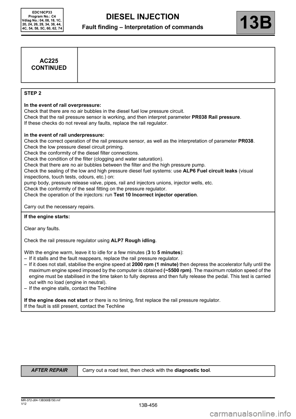
AC225
CONTINUED
STEP 2
In the event of rail overpressure:
Check that there are no air bubbles in the diesel fuel low pressure circuit.
Check that the rail pressure sensor is working, and then interpret parameter PR038 Rail pressure.
If these checks do not reveal any faults, replace the rail regulator.
in the event of rail underpressure:
Check the correct operation of the rail pressure sensor, as well as the interpretation of parameter PR038.
Check the low pressure diesel circuit priming.
Check the conformity of the diesel filter connections.
Check the condition of the filter (clogging and water saturation).
Check that there are no air bubbles between the filter and the high pressure pump.
Check the sealing of the low and high pressure diesel fuel systems: use ALP6 Fuel circuit leaks (visual
inspections, touch tests, odours, etc.) on:
pump body, pressure release valve, pipes, rail and injectors unions, injector wells, etc.
Check the conformity of the seal fitting on the pressure regulator.
Check the operation of the injectors: run Test 10 Incorrect injector operation.
Carry out the necessary repairs.
If the engine starts:
Clear any faults.
Check the rail pressure regulator using ALP7 Rough idling.
With the engine warm, leave it to idle for a few minutes (3 to 5 minutes):
– If it stalls and the fault reappears, replace the rail pressure regulator.
– If it does not stall, stabilise the engine speed at 2000 rpm (1 minute) then depress the accelerator fully until the
maximum engine speed imposed by the computer is obtained (~5500 rpm). The maximum rotation speed of the
engine must be stabilised in the time taken to fully depress and then fully release the pedal. This test is carried
out with no load (engine in neutral).
– If the engine stalls, contact the Techline
If the engine does not start or there is no timing, first replace the rail pressure regulator.
If the fault is still present, contact the Techline
EDC16CP33
Program No.: C4
Vdiag No.: 04, 08, 18, 1C,
20, 24, 26, 28, 34, 38, 44,
4C, 54, 58, 5C, 60, 62, 74
AFTER REPAIRCarry out a road test, then check with the diagnostic tool.
Page 458 of 510
13B-458V12 MR-372-J84-13B300$150.mif
DIESEL INJECTION
Fault finding – Interpretation of commands13B
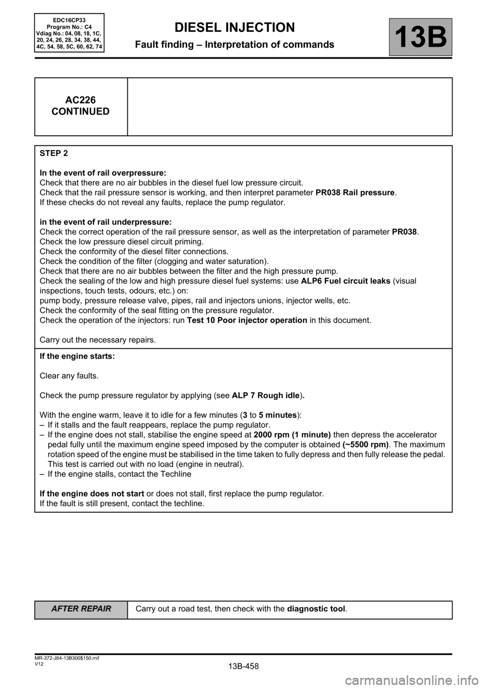
AC226
CONTINUED
STEP 2
In the event of rail overpressure:
Check that there are no air bubbles in the diesel fuel low pressure circuit.
Check that the rail pressure sensor is working, and then interpret parameter PR038 Rail pressure.
If these checks do not reveal any faults, replace the pump regulator.
in the event of rail underpressure:
Check the correct operation of the rail pressure sensor, as well as the interpretation of parameter PR038.
Check the low pressure diesel circuit priming.
Check the conformity of the diesel filter connections.
Check the condition of the filter (clogging and water saturation).
Check that there are no air bubbles between the filter and the high pressure pump.
Check the sealing of the low and high pressure diesel fuel systems: use ALP6 Fuel circuit leaks (visual
inspections, touch tests, odours, etc.) on:
pump body, pressure release valve, pipes, rail and injectors unions, injector wells, etc.
Check the conformity of the seal fitting on the pressure regulator.
Check the operation of the injectors: run Test 10 Poor injector operation in this document.
Carry out the necessary repairs.
If the engine starts:
Clear any faults.
Check the pump pressure regulator by applying (see ALP 7 Rough idle).
With the engine warm, leave it to idle for a few minutes (3 to 5 minutes):
– If it stalls and the fault reappears, replace the pump regulator.
– If the engine does not stall, stabilise the engine speed at 2000 rpm (1 minute) then depress the accelerator
pedal fully until the maximum engine speed imposed by the computer is obtained (~5500 rpm). The maximum
rotation speed of the engine must be stabilised in the time taken to fully depress and then fully release the pedal.
This test is carried out with no load (engine in neutral).
– If the engine stalls, contact the Techline
If the engine does not start or does not stall, first replace the pump regulator.
If the fault is still present, contact the techline.
EDC16CP33
Program No.: C4
Vdiag No.: 04, 08, 18, 1C,
20, 24, 26, 28, 34, 38, 44,
4C, 54, 58, 5C, 60, 62, 74
AFTER REPAIRCarry out a road test, then check with the diagnostic tool.
Page 469 of 510
13B-469
AFTER REPAIRCarry out a road test followed by a check with the diagnostic tool.
V12 MR-372-J84-13B300$160.mif
13B
EDC16CP33
Program No.: C4
Vdiag No.: 04, 08, 18, 1C,
20, 24, 26, 28, 34, 38, 44,
4C, 54, 58, 5C, 60, 62, 74
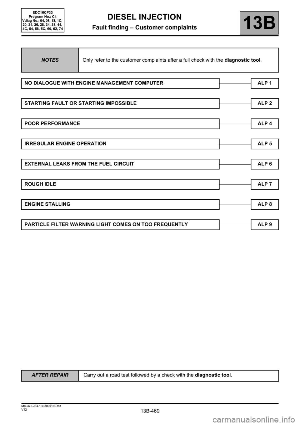
NOTESOnly refer to the customer complaints after a full check with the diagnostic tool.
NO DIALOGUE WITH ENGINE MANAGEMENT COMPUTER ALP 1
STARTING FAULT OR STARTING IMPOSSIBLE ALP 2
POOR PERFORMANCEALP 4
IRREGULAR ENGINE OPERATION ALP 5
EXTERNAL LEAKS FROM THE FUEL CIRCUIT ALP 6
ROUGH IDLEALP 7
ENGINE STALLINGALP 8
PARTICLE FILTER WARNING LIGHT COMES ON TOO FREQUENTLY ALP 9
DIESEL INJECTION
Fault finding – Customer complaints
Page 475 of 510
13B-475
AFTER REPAIRCarry out a road test, then check with the diagnostic tool.
V12 MR-372-J84-13B300$170.mif
DIESEL INJECTION
Fault finding – Fault Finding Chart13B
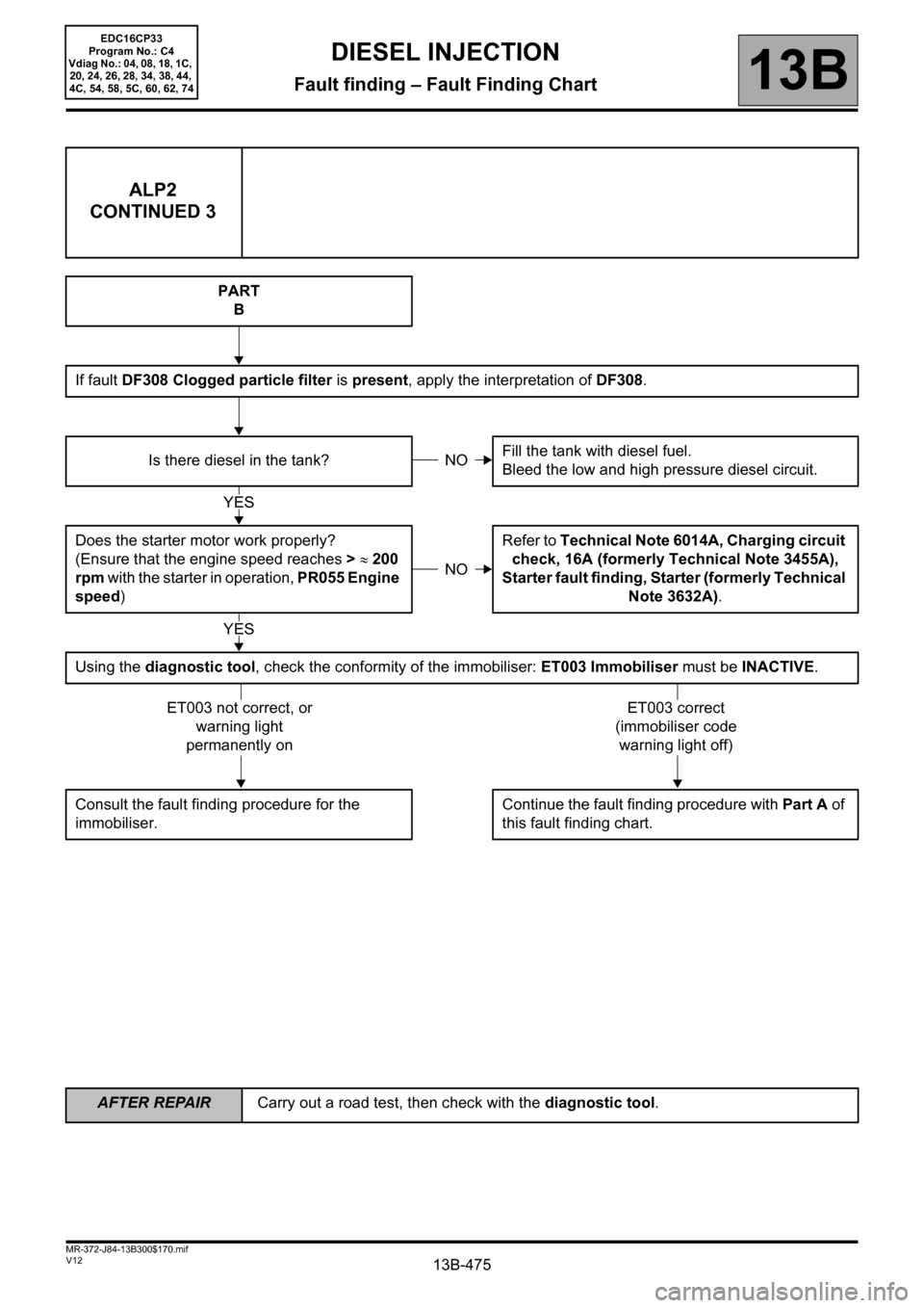
ALP2
CONTINUED 3
PART
B
If fault DF308 Clogged particle filter is present, apply the interpretation of DF308.
Is there diesel in the tank?Fill the tank with diesel fuel.
Bleed the low and high pressure diesel circuit.
Does the starter motor work properly?
(Ensure that the engine speed reaches > ≈ 200
rpm with the starter in operation, PR055 Engine
speed)Refer to Technical Note 6014A, Charging circuit
check, 16A (formerly Technical Note 3455A),
Starter fault finding, Starter (formerly Technical
Note 3632A).
Using the diagnostic tool, check the conformity of the immobiliser: ET003 Immobiliser must be INACTIVE.
Consult the fault finding procedure for the
immobiliser.Continue the fault finding procedure with Part A of
this fault finding chart.
NO
YES
NO
YES
ET003 not correct, or
warning light
permanently onET003 correct
(immobiliser code
warning light off)
EDC16CP33
Program No.: C4
Vdiag No.: 04, 08, 18, 1C,
20, 24, 26, 28, 34, 38, 44,
4C, 54, 58, 5C, 60, 62, 74
Page 477 of 510
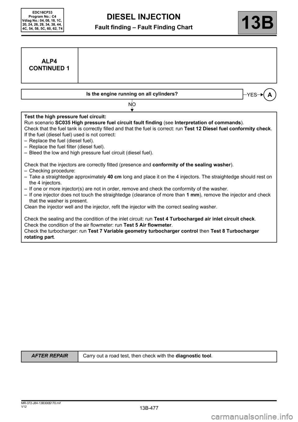
13B-477
AFTER REPAIRCarry out a road test, then check with the diagnostic tool.
V12 MR-372-J84-13B300$170.mif
DIESEL INJECTION
Fault finding – Fault Finding Chart13B
ALP4
CONTINUED 1
Is the engine running on all cylinders?
Test the high pressure fuel circuit:
Run scenario SC035 High pressure fuel circuit fault finding (see Interpretation of commands).
Check that the fuel tank is correctly filled and that the fuel is correct: run Test 12 Diesel fuel conformity check.
If the fuel (diesel fuel) used is not correct:
– Replace the fuel (diesel fuel).
– Replace the fuel filter (diesel fuel).
– Bleed the low and high pressure fuel circuit (diesel fuel).
Check that the injectors are correctly fitted (presence and conformity of the sealing washer).
– Checking procedure:
– Take a straightedge approximately 40 cm long and place it on the 4 injectors. The straightedge should rest on
the 4 injectors.
– If one or more injector(s) are not in order, remove and check the conformity of the washer.
– If one injector does not touch the straightedge (clearance of more than 1mm), remove the injector and check
that the washer is present.
Clean the injector well and the injector, refit the injector with the correct sealing washer.
Check the sealing and the condition of the inlet circuit: run Test 4 Turbocharged air inlet circuit check.
Check the condition of the air flowmeter: run Test 5 Air flowmeter.
Check the turbocharger: run Test 7 Variable geometry turbocharger control then Test 8 Turbocharger
rotating part.AYES
NO
EDC16CP33
Program No.: C4
Vdiag No.: 04, 08, 18, 1C,
20, 24, 26, 28, 34, 38, 44,
4C, 54, 58, 5C, 60, 62, 74