heating RENAULT SCENIC 2012 J95 / 3.G Engine And Peripherals EDC16CP33 Owner's Manual
[x] Cancel search | Manufacturer: RENAULT, Model Year: 2012, Model line: SCENIC, Model: RENAULT SCENIC 2012 J95 / 3.GPages: 510, PDF Size: 2.98 MB
Page 283 of 510
13B-283V12 MR-372-J84-13B300$101.mif
DIESEL INJECTION
Fault finding – Interpretation of statuses13B
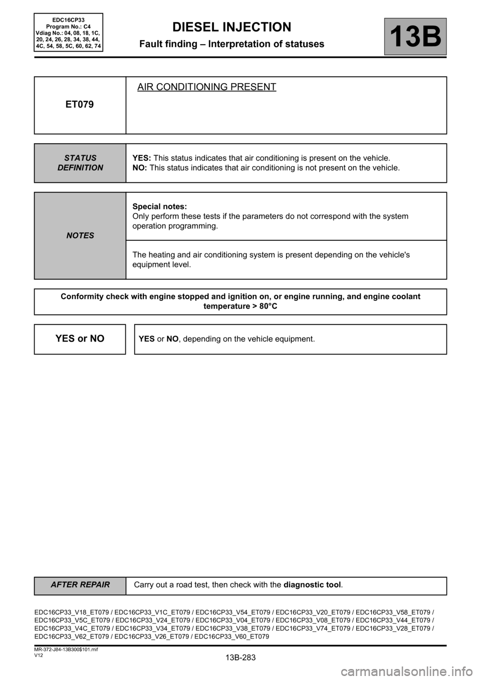
ET079AIR CONDITIONING PRESENT
STATUS
DEFINITIONYES: This status indicates that air conditioning is present on the vehicle.
NO: This status indicates that air conditioning is not present on the vehicle.
NOTESSpecial notes:
Only perform these tests if the parameters do not correspond with the system
operation programming.
The heating and air conditioning system is present depending on the vehicle's
equipment level.
Conformity check with engine stopped and ignition on, or engine running, and engine coolant
temperature > 80°C
YES or NOYES or NO, depending on the vehicle equipment.
EDC16CP33_V18_ET079 / EDC16CP33_V1C_ET079 / EDC16CP33_V54_ET079 / EDC16CP33_V20_ET079 / EDC16CP33_V58_ET079 /
EDC16CP33_V5C_ET079 / EDC16CP33_V24_ET079 / EDC16CP33_V04_ET079 / EDC16CP33_V08_ET079 / EDC16CP33_V44_ET079 /
EDC16CP33_V4C_ET079 / EDC16CP33_V34_ET079 / EDC16CP33_V38_ET079 / EDC16CP33_V74_ET079 / EDC16CP33_V28_ET079 /
EDC16CP33_V62_ET079 / EDC16CP33_V26_ET079 / EDC16CP33_V60_ET079
AFTER REPAIRCarry out a road test, then check with the diagnostic tool.
EDC16CP33
Program No.: C4
Vdiag No.: 04, 08, 18, 1C,
20, 24, 26, 28, 34, 38, 44,
4C, 54, 58, 5C, 60, 62, 74
Page 285 of 510
13B-285V12 MR-372-J84-13B300$101.mif
DIESEL INJECTION
Fault finding – Interpretation of statuses13B
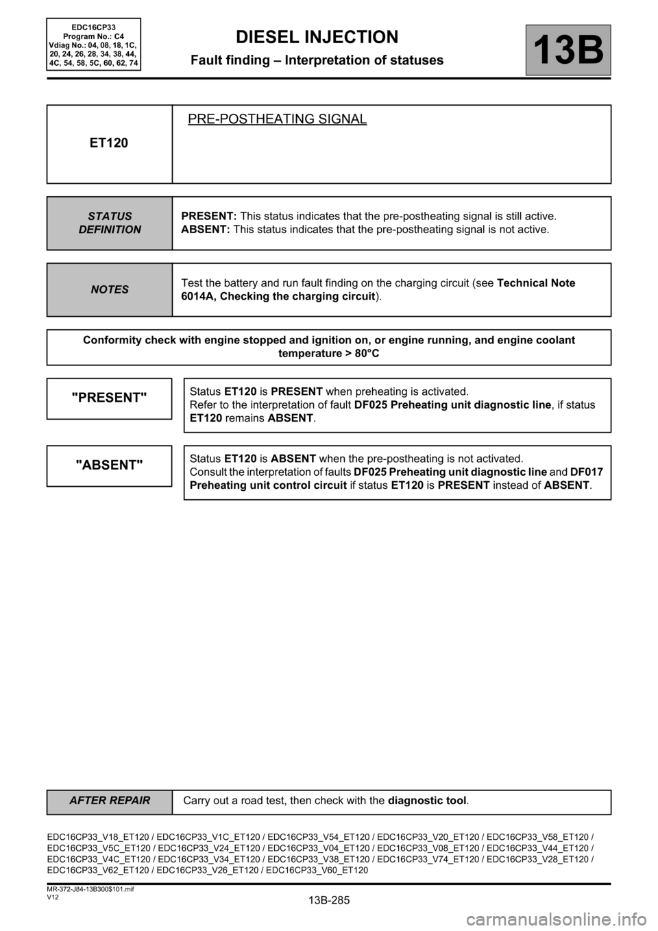
ET120PRE-POSTHEATING SIGNAL
STATUS
DEFINITIONPRESENT: This status indicates that the pre-postheating signal is still active.
ABSENT: This status indicates that the pre-postheating signal is not active.
NOTESTest the battery and run fault finding on the charging circuit (see Technical Note
6014A, Checking the charging circuit).
Conformity check with engine stopped and ignition on, or engine running, and engine coolant
temperature > 80°C
"PRESENT"Status ET120 is PRESENT when preheating is activated.
Refer to the interpretation of fault DF025 Preheating unit diagnostic line, if status
ET120 remains ABSENT.
"ABSENT"Status ET120 is ABSENT when the pre-postheating is not activated.
Consult the interpretation of faults DF025 Preheating unit diagnostic line and DF017
Preheating unit control circuit if status ET120 is PRESENT instead of ABSENT.
EDC16CP33_V18_ET120 / EDC16CP33_V1C_ET120 / EDC16CP33_V54_ET120 / EDC16CP33_V20_ET120 / EDC16CP33_V58_ET120 /
EDC16CP33_V5C_ET120 / EDC16CP33_V24_ET120 / EDC16CP33_V04_ET120 / EDC16CP33_V08_ET120 / EDC16CP33_V44_ET120 /
EDC16CP33_V4C_ET120 / EDC16CP33_V34_ET120 / EDC16CP33_V38_ET120 / EDC16CP33_V74_ET120 / EDC16CP33_V28_ET120 /
EDC16CP33_V62_ET120 / EDC16CP33_V26_ET120 / EDC16CP33_V60_ET120
AFTER REPAIRCarry out a road test, then check with the diagnostic tool.
EDC16CP33
Program No.: C4
Vdiag No.: 04, 08, 18, 1C,
20, 24, 26, 28, 34, 38, 44,
4C, 54, 58, 5C, 60, 62, 74
Page 292 of 510
13B-292V12 MR-372-J84-13B300$101.mif
DIESEL INJECTION
Fault finding – Interpretation of statuses13B
Only for Laguna II ph2 without a particle filter
ET205
ET206
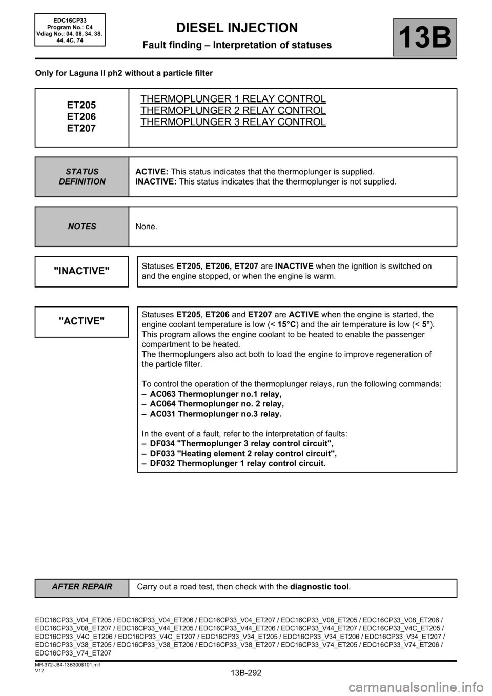
ET207THERMOPLUNGER 1 RELAY CONTROLTHERMOPLUNGER 2 RELAY CONTROL
THERMOPLUNGER 3 RELAY CONTROL
STATUS
DEFINITIONACTIVE: This status indicates that the thermoplunger is supplied.
INACTIVE: This status indicates that the thermoplunger is not supplied.
NOTESNone.
"INACTIVE"Statuses ET205, ET206, ET207 are INACTIVE when the ignition is switched on
and the engine stopped, or when the engine is warm.
"ACTIVE"Statuses ET205, ET206 and ET207 are ACTIVE when the engine is started, the
engine coolant temperature is low (<15°C) and the air temperature is low (<5°).
This program allows the engine coolant to be heated to enable the passenger
compartment to be heated.
The thermoplungers also act both to load the engine to improve regeneration of
the particle filter.
To control the operation of the thermoplunger relays, run the following commands:
– AC063 Thermoplunger no.1 relay,
– AC064 Thermoplunger no. 2 relay,
– AC031 Thermoplunger no.3 relay.
In the event of a fault, refer to the interpretation of faults:
– DF034 "Thermoplunger 3 relay control circuit",
– DF033 "Heating element 2 relay control circuit",
– DF032 Thermoplunger 1 relay control circuit.
EDC16CP33_V04_ET205 / EDC16CP33_V04_ET206 / EDC16CP33_V04_ET207 / EDC16CP33_V08_ET205 / EDC16CP33_V08_ET206 /
EDC16CP33_V08_ET207 / EDC16CP33_V44_ET205 / EDC16CP33_V44_ET206 / EDC16CP33_V44_ET207 / EDC16CP33_V4C_ET205 /
EDC16CP33_V4C_ET206 / EDC16CP33_V4C_ET207 / EDC16CP33_V34_ET205 / EDC16CP33_V34_ET206 / EDC16CP33_V34_ET207 /
EDC16CP33_V38_ET205 / EDC16CP33_V38_ET206 / EDC16CP33_V38_ET207 / EDC16CP33_V74_ET205 / EDC16CP33_V74_ET206 /
EDC16CP33_V74_ET207
AFTER REPAIRCarry out a road test, then check with the diagnostic tool.
EDC16CP33
Program No.: C4
Vdiag No.: 04, 08, 34, 38,
44, 4C, 74
Page 351 of 510
13B-351
AFTER REPAIRCarry out a road test, then check with the diagnostic tool.
V12 MR-372-J84-13B300$121.mif
DIESEL INJECTION
Fault finding – Interpretation of parameters13B
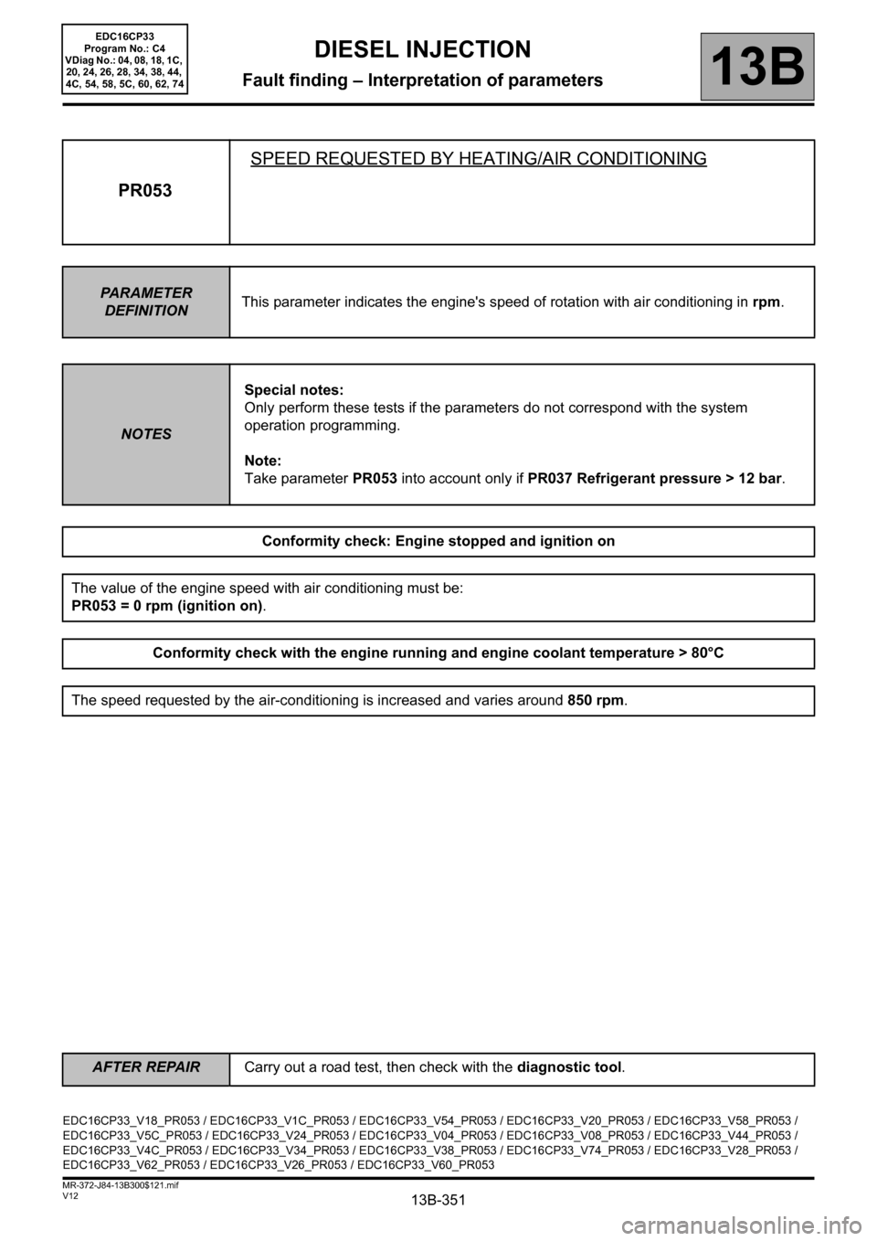
PR053SPEED REQUESTED BY HEATING/AIR CONDITIONING
PARAMETER
DEFINITIONThis parameter indicates the engine's speed of rotation with air conditioning in rpm.
NOTESSpecial notes:
Only perform these tests if the parameters do not correspond with the system
operation programming.
Note:
Take parameter PR053 into account only if PR037 Refrigerant pressure > 12 bar.
Conformity check: Engine stopped and ignition on
The value of the engine speed with air conditioning must be:
PR053 = 0 rpm (ignition on).
Conformity check with the engine running and engine coolant temperature > 80°C
The speed requested by the air-conditioning is increased and varies around 850 rpm.
EDC16CP33_V18_PR053 / EDC16CP33_V1C_PR053 / EDC16CP33_V54_PR053 / EDC16CP33_V20_PR053 / EDC16CP33_V58_PR053 /
EDC16CP33_V5C_PR053 / EDC16CP33_V24_PR053 / EDC16CP33_V04_PR053 / EDC16CP33_V08_PR053 / EDC16CP33_V44_PR053 /
EDC16CP33_V4C_PR053 / EDC16CP33_V34_PR053 / EDC16CP33_V38_PR053 / EDC16CP33_V74_PR053 / EDC16CP33_V28_PR053 /
EDC16CP33_V62_PR053 / EDC16CP33_V26_PR053 / EDC16CP33_V60_PR053
EDC16CP33
Program No.: C4
VDiag No.: 04, 08, 18, 1C,
20, 24, 26, 28, 34, 38, 44,
4C, 54, 58, 5C, 60, 62, 74
Page 422 of 510
13B-422V12 MR-372-J84-13B300$140.mif
13B
EDC16CP33
Program No.: C4
Vdiag No.: 04, 08, 18, 1C,
20, 24, 26, 28, 34, 38, 44,
4C, 54, 58, 5C, 60, 62, 74
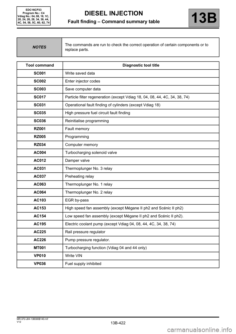
NOTESThe commands are run to check the correct operation of certain components or to
replace parts.
Tool command Diagnostic tool title
SC001Write saved data
SC002Enter injector codes
SC003Save computer data
SC017Particle filter regeneration (except Vdiag 18, 04, 08, 44, 4C, 34, 38, 74)
SC031Operational fault finding of cylinders (except Vdiag 18)
SC035High pressure fuel circuit fault finding
SC036Reinitialise programming
RZ001Fault memory
RZ005Programming
RZ034Computer memory
AC004Turbocharging solenoid valve
AC012Damper valve
AC031Thermoplunger No. 3 relay
AC037Preheating relay
AC063Thermoplunger No. 1 relay
AC064Thermoplunger No. 2 relay
AC103EGR by-pass
AC153High speed fan assembly (except Mégane II ph2 and Scénic II ph2)
AC154Low speed fan assembly (except Mégane II ph2 and Scénic II ph2).
AC195Electric coolant pump (except Vdiag 04, 08, 44, 4C, 34, 38, 74)
AC225Rail pressure regulator
AC226Pump pressure regulator.
MT001Turbocharging function (Vdiag 04 and 44 only)
VP010Write VIN
VP036Fuel supply inhibited
DIESEL INJECTION
Fault finding – Command summary table
Page 428 of 510
13B-428V12 MR-372-J84-13B300$150.mif
DIESEL INJECTION
Fault finding – Interpretation of commands13B
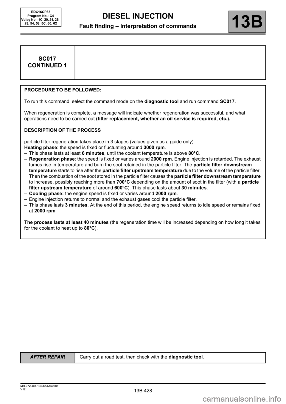
SC017
CONTINUED 1
PROCEDURE TO BE FOLLOWED:
To run this command, select the command mode on the diagnostic tool and run command SC017.
When regeneration is complete, a message will indicate whether regeneration was successful, and what
operations need to be carried out (filter replacement, whether an oil service is required, etc.).
DESCRIPTION OF THE PROCESS
particle filter regeneration takes place in 3 stages (values given as a guide only):
Heating phase: the speed is fixed or fluctuating around 3000 rpm.
– This phase lasts at least 6minutes, until the coolant temperature is above 80°C.
–Regeneration phase: the speed is fixed or varies around 2000 rpm. Engine injection is retarded. The exhaust
fumes rise in temperature and burn the soot retained in the particle filter. The particle filter downstream
temperature starts to rise after the particle filter upstream temperature due to the volume of the particle filter.
Then the combustion of the soot stored in the particle filter causes the particle filter downstream temperature
to increase, possibly reaching more than 700°C depending on the amount of soot in the filter (with a particle
filter upstream temperature of around 600°C). This phase lasts about 30 minutes.
–Cooling phase: the engine speed is fixed or varies around 2000 rpm.
– Engine injection returns to normal and the exhaust gases cool the particle filter.
– This phase lasts 3 minutes. At the end of this period, the engine speed returns to idle speed or remains fixed
at 2000 rpm.
The process lasts at least 40 minutes (the regeneration time will be increased depending on how long it takes
for the coolant to heat up to 80°C).
EDC16CP33
Program No.: C4
Vdiag No.: 1C, 20, 24, 26,
28, 54, 58, 5C, 60, 62
AFTER REPAIRCarry out a road test, then check with the diagnostic tool.
Page 437 of 510
13B-437V12 MR-372-J84-13B300$150.mif
DIESEL INJECTION
Fault finding – Interpretation of commands13B
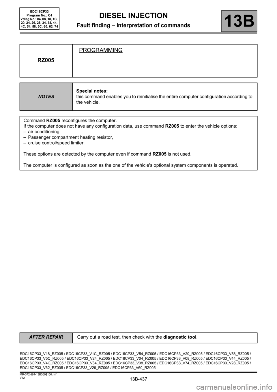
RZ005PROGRAMMING
NOTESSpecial notes:
this command enables you to reinitialise the entire computer configuration according to
the vehicle.
Command RZ005 reconfigures the computer.
If the computer does not have any configuration data, use command RZ005 to enter the vehicle options:
– air conditioning,
– Passenger compartment heating resistor,
– cruise control/speed limiter.
These options are detected by the computer even if command RZ005 is not used.
The computer is configured as soon as the one of the vehicle's optional system components is operated.
EDC16CP33_V18_RZ005 / EDC16CP33_V1C_RZ005 / EDC16CP33_V54_RZ005 / EDC16CP33_V20_RZ005 / EDC16CP33_V58_RZ005 /
EDC16CP33_V5C_RZ005 / EDC16CP33_V24_RZ005 / EDC16CP33_V04_RZ005 / EDC16CP33_V08_RZ005 / EDC16CP33_V44_RZ005 /
EDC16CP33_V4C_RZ005 / EDC16CP33_V34_RZ005 / EDC16CP33_V38_RZ005 / EDC16CP33_V74_RZ005 / EDC16CP33_V28_RZ005 /
EDC16CP33_V62_RZ005 / EDC16CP33_V26_RZ005 / EDC16CP33_V60_RZ005
EDC16CP33
Program No.: C4
Vdiag No.: 04, 08, 18, 1C,
20, 24, 26, 28, 34, 38, 44,
4C, 54, 58, 5C, 60, 62, 74
AFTER REPAIRCarry out a road test, then check with the diagnostic tool.
Page 442 of 510
13B-442V12 MR-372-J84-13B300$150.mif
DIESEL INJECTION
Fault finding – Interpretation of commands13B
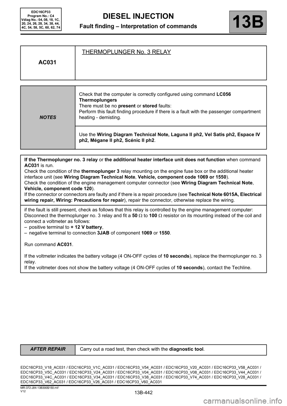
AC031THERMOPLUNGER No. 3 RELAY
NOTESCheck that the computer is correctly configured using command LC056
Thermoplungers
There must be no present or stored faults:
Perform this fault finding procedure if there is a fault with the passenger compartment
heating - demisting.
Use the Wiring Diagram Technical Note, Laguna II ph2, Vel Satis ph2, Espace IV
ph2, Mégane II ph2, Scénic II ph2.
If the Thermoplunger no. 3 relay or the additional heater interface unit does not function when command
AC031 is run.
Check the condition of the thermoplunger 3 relay mounting on the engine fuse box or the additional heater
interface unit (see Wiring Diagram Technical Note, Vehicle, component code 1069 or 1550).
Check the condition of the engine management computer connector (see Wiring Diagram Technical Note,
Vehicle, component code 120).
If the connector or connectors are faulty and if there is a repair procedure (see Technical Note 6015A, Electrical
wiring repair, Wiring: Precautions for repair), repair the connector, otherwise replace the wiring.
if the fault is still present, check as follows that this relay is controlled by the engine management computer:
Disconnect the thermoplunger no. 3 relay and fit a 50 Ω to 100Ω resistor on its mounting instead of the coil and
connect a voltmeter as follows:
– positive terminal to + 12 V battery,
– negative terminal to connection 3JAB of component 1069 or 1550.
Run command AC031.
If the voltmeter indicates the battery voltage (4 ON-OFF cycles of 10 seconds), replace the thermoplunger no. 3
relay.
If the voltmeter does not show the battery voltage (4 ON-OFF cycles of 10 seconds), contact the Techline.
EDC16CP33_V18_AC031 / EDC16CP33_V1C_AC031 / EDC16CP33_V54_AC031 / EDC16CP33_V20_AC031 / EDC16CP33_V58_AC031 /
EDC16CP33_V5C_AC031 / EDC16CP33_V24_AC031 / EDC16CP33_V04_AC031 / EDC16CP33_V08_AC031 / EDC16CP33_V44_AC031 /
EDC16CP33_V4C_AC031 / EDC16CP33_V34_AC031 / EDC16CP33_V38_AC031 / EDC16CP33_V74_AC031 / EDC16CP33_V28_AC031 /
EDC16CP33_V62_AC031 / EDC16CP33_V26_AC031 / EDC16CP33_V60_AC031
EDC16CP33
Program No.: C4
Vdiag No.: 04, 08, 18, 1C,
20, 24, 26, 28, 34, 38, 44,
4C, 54, 58, 5C, 60, 62, 74
AFTER REPAIRCarry out a road test, then check with the diagnostic tool.
Page 443 of 510
13B-443V12 MR-372-J84-13B300$150.mif
DIESEL INJECTION
Fault finding – Interpretation of commands13B
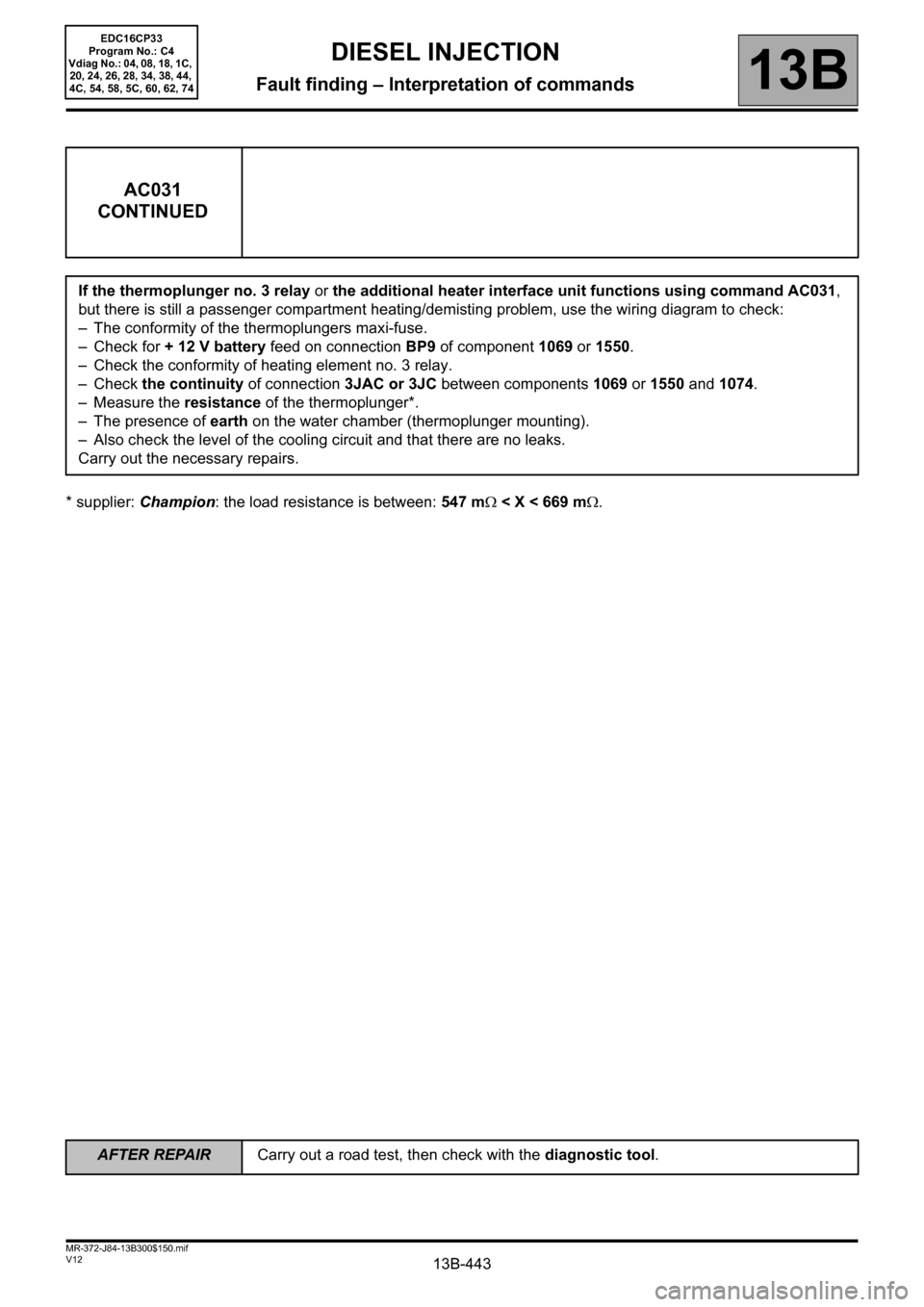
* supplier: Champion: the load resistance is between: 547 mΩ < X < 669 mΩ.
AC031
CONTINUED
If the thermoplunger no. 3 relay or the additional heater interface unit functions using command AC031,
but there is still a passenger compartment heating/demisting problem, use the wiring diagram to check:
– The conformity of the thermoplungers maxi-fuse.
– Check for + 12 V battery feed on connection BP9 of component 1069 or 1550.
– Check the conformity of heating element no. 3 relay.
– Check the continuity of connection 3JAC or 3JC between components 1069 or 1550 and 1074.
– Measure the resistance of the thermoplunger*.
– The presence of earth on the water chamber (thermoplunger mounting).
– Also check the level of the cooling circuit and that there are no leaks.
Carry out the necessary repairs.
EDC16CP33
Program No.: C4
Vdiag No.: 04, 08, 18, 1C,
20, 24, 26, 28, 34, 38, 44,
4C, 54, 58, 5C, 60, 62, 74
AFTER REPAIRCarry out a road test, then check with the diagnostic tool.
Page 444 of 510
13B-444V12 MR-372-J84-13B300$150.mif
DIESEL INJECTION
Fault finding – Interpretation of commands13B
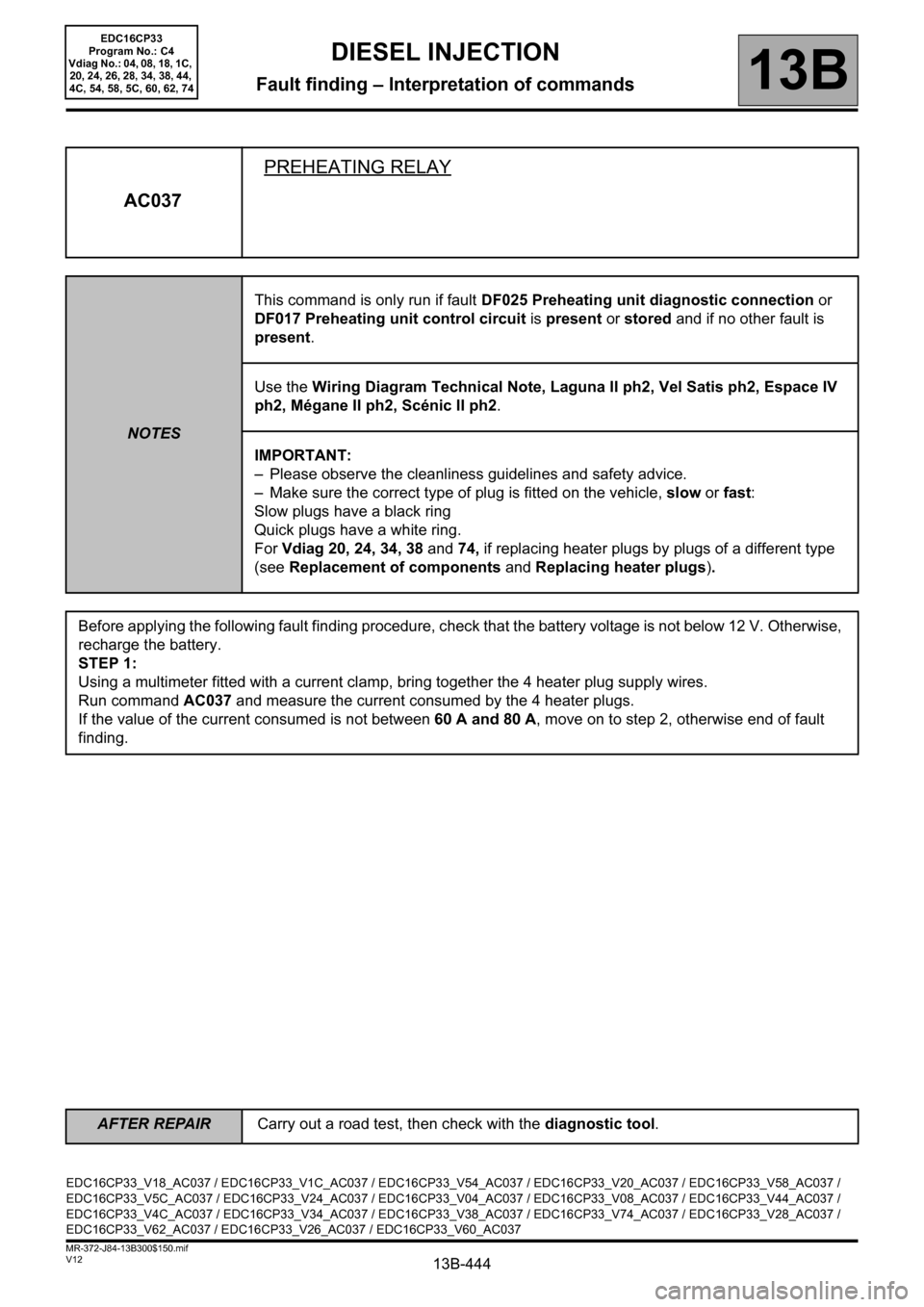
AC037PREHEATING RELAY
NOTESThis command is only run if fault DF025 Preheating unit diagnostic connection or
DF017 Preheating unit control circuit is present or stored and if no other fault is
present.
Use the Wiring Diagram Technical Note, Laguna II ph2, Vel Satis ph2, Espace IV
ph2, Mégane II ph2, Scénic II ph2.
IMPORTANT:
– Please observe the cleanliness guidelines and safety advice.
– Make sure the correct type of plug is fitted on the vehicle, slow or fast:
Slow plugs have a black ring
Quick plugs have a white ring.
For Vdiag 20, 24, 34, 38 and 74, if replacing heater plugs by plugs of a different type
(see Replacement of components and Replacing heater plugs).
Before applying the following fault finding procedure, check that the battery voltage is not below 12 V. Otherwise,
recharge the battery.
STEP 1:
Using a multimeter fitted with a current clamp, bring together the 4 heater plug supply wires.
Run command AC037 and measure the current consumed by the 4 heater plugs.
If the value of the current consumed is not between 60 A and 80 A, move on to step 2, otherwise end of fault
finding.
EDC16CP33_V18_AC037 / EDC16CP33_V1C_AC037 / EDC16CP33_V54_AC037 / EDC16CP33_V20_AC037 / EDC16CP33_V58_AC037 /
EDC16CP33_V5C_AC037 / EDC16CP33_V24_AC037 / EDC16CP33_V04_AC037 / EDC16CP33_V08_AC037 / EDC16CP33_V44_AC037 /
EDC16CP33_V4C_AC037 / EDC16CP33_V34_AC037 / EDC16CP33_V38_AC037 / EDC16CP33_V74_AC037 / EDC16CP33_V28_AC037 /
EDC16CP33_V62_AC037 / EDC16CP33_V26_AC037 / EDC16CP33_V60_AC037
EDC16CP33
Program No.: C4
Vdiag No.: 04, 08, 18, 1C,
20, 24, 26, 28, 34, 38, 44,
4C, 54, 58, 5C, 60, 62, 74
AFTER REPAIRCarry out a road test, then check with the diagnostic tool.