alternator RENAULT SCENIC 2012 J95 / 3.G Engine And Peripherals EDC16CP33 Workshop Manual
[x] Cancel search | Manufacturer: RENAULT, Model Year: 2012, Model line: SCENIC, Model: RENAULT SCENIC 2012 J95 / 3.GPages: 510, PDF Size: 2.98 MB
Page 9 of 510
13B-9V12 MR-372-J84-13B300$020.mif
DIESEL INJECTION
Fault finding – Cleanliness guidelines13B
EDC16CP33
Program No.: C4
Vdiag No.: 04, 08, 18, 1C,
20, 24, 26, 28, 34, 38, 44,
4C, 54, 58, 5C, 60, 62, 74
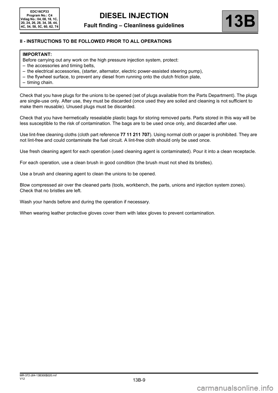
II - INSTRUCTIONS TO BE FOLLOWED PRIOR TO ALL OPERATIONS
Check that you have plugs for the unions to be opened (set of plugs available from the Parts Department). The plugs
are single-use only. After use, they must be discarded (once used they are soiled and cleaning is not sufficient to
make them reusable). Unused plugs must be discarded.
Check that you have hermetically resealable plastic bags for storing removed parts. Parts stored in this way will be
less susceptible to the risk of contamination. The bags are to be used once only, and discarded after use.
Use lint-free cleaning cloths (cloth part reference 77 11 211 707). Using normal cloth or paper is prohibited. They are
not lint-free and could contaminate the fuel circuit. A lint-free cloth should only be used once.
Use fresh cleaning agent for each operation (used cleaning agent is contaminated). Pour it into a clean receptacle.
For each operation, use a clean brush in good condition (the brush must not shed its bristles).
Use a brush and cleaning agent to clean the unions to be opened.
Blow compressed air over the cleaned parts (tools, workbench, the parts, unions and injection system zones).
Check that no bristles are left.
Wash your hands before and during the operation if necessary.
When wearing leather protective gloves cover them with latex gloves to prevent contamination. IMPORTANT:
Before carrying out any work on the high pressure injection system, protect:
– the accessories and timing belts,
– the electrical accessories, (starter, alternator, electric power-assisted steering pump),
– the flywheel surface, to prevent any diesel from running onto the clutch friction plate,
– timing chain.
Page 30 of 510
13B-30V12 MR-372-J84-13B300$060.mif
DIESEL INJECTION
Fault finding – Fault summary table13B
EDC16CP33
Program No.: C4
Vdiag No.: 04, 08, 18, 1C,
20, 24, 26, 28, 34, 38, 44,
4C, 54, 58, 5C, 60, 62, 74
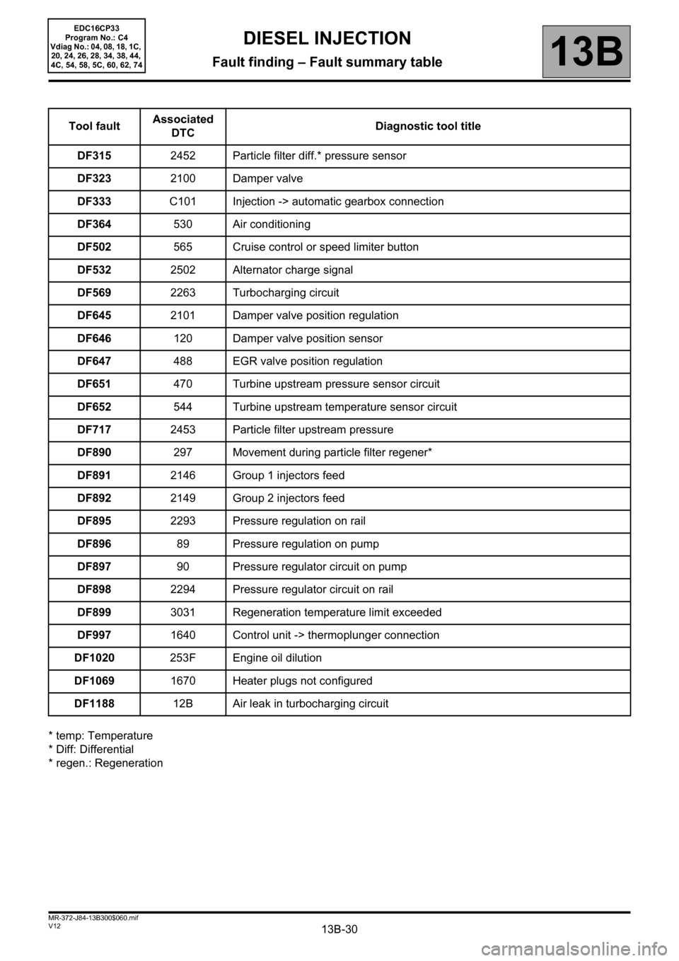
* temp: Temperature
* Diff: Differential
* regen.: RegenerationTool faultAssociated
DTCDiagnostic tool title
DF3152452 Particle filter diff.* pressure sensor
DF3232100 Damper valve
DF333C101 Injection -> automatic gearbox connection
DF364530 Air conditioning
DF502565 Cruise control or speed limiter button
DF5322502 Alternator charge signal
DF5692263 Turbocharging circuit
DF6452101 Damper valve position regulation
DF646120 Damper valve position sensor
DF647488 EGR valve position regulation
DF651470 Turbine upstream pressure sensor circuit
DF652544 Turbine upstream temperature sensor circuit
DF7172453 Particle filter upstream pressure
DF890297 Movement during particle filter regener*
DF8912146 Group 1 injectors feed
DF8922149 Group 2 injectors feed
DF8952293 Pressure regulation on rail
DF89689 Pressure regulation on pump
DF89790 Pressure regulator circuit on pump
DF8982294 Pressure regulator circuit on rail
DF8993031 Regeneration temperature limit exceeded
DF9971640 Control unit -> thermoplunger connection
DF1020253F Engine oil dilution
DF10691670 Heater plugs not configured
DF118812B Air leak in turbocharging circuit
Page 216 of 510
13B-216
AFTER REPAIRDeal with any other faults. Clear the fault memory.
Switch off the ignition until the end of the power-latch phase, and carry out a road test
followed by a check with the diagnostic tool.
V12 MR-372-J84-13B300$074.mif
DIESEL INJECTION
Fault finding – Interpretation of faults13B
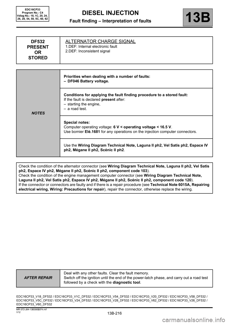
DF532
PRESENT
OR
STOREDALTERNATOR CHARGE SIGNAL
1.DEF: Internal electronic fault
2.DEF: Inconsistent signal
NOTESPriorities when dealing with a number of faults:
– DF046 Battery voltage.
Conditions for applying the fault finding procedure to a stored fault:
If the fault is declared present after:
– starting the engine,
– a road test.
Special notes:
Computer operating voltage: 6 V < operating voltage < 16.5 V.
Use bornier Elé.1681 for any operations on the injection computer connectors.
Use the Wiring Diagram Technical Note, Laguna II ph2, Vel Satis ph2, Espace IV
ph2, Mégane II ph2, Scénic II ph2.
Check the condition of the alternator connector (see Wiring Diagram Technical Note, Laguna II ph2, Vel Satis
ph2, Espace IV ph2, Mégane II ph2, Scénic II ph2, component code 103).
Check the condition of the engine management computer connector (see Wiring Diagram Technical Note,
Laguna II ph2, Vel Satis ph2, Espace IV ph2, Mégane II ph2, Scénic II ph2, component code 120).
If the connector or connectors are faulty and if there is a repair procedure (see Technical Note 6015A, Repairing
electrical wiring, Wiring: Precautions for repair), repair the connector, otherwise replace the wiring.
EDC16CP33_V18_DF532 / EDC16CP33_V1C_DF532 / EDC16CP33_V54_DF532 / EDC16CP33_V20_DF532 / EDC16CP33_V58_DF532 /
EDC16CP33_V5C_DF532 / EDC16CP33_V24_DF532 / EDC16CP33_V28_DF532 / EDC16CP33_V62_DF532 / EDC16CP33_V26_DF532 /
EDC16CP33_V60_DF532
EDC16CP33
Program No.: C4
Vdiag No.: 18, 1C, 20, 24,
26, 28, 54, 58, 5C, 60, 62
Page 325 of 510
13B-325V12 MR-372-J84-13B300$110.mif
13B
EDC16CP33
Program No.: C4
VDiag No.: 04, 08, 18, 1C,
20, 24, 26, 28, 34, 38, 44,
4C, 54, 58, 5C, 60, 62, 74
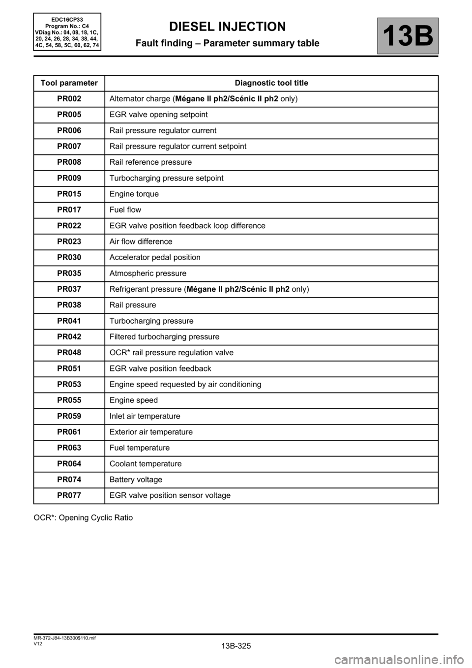
OCR*: Opening Cyclic RatioTool parameter Diagnostic tool title
PR002Alternator charge (Mégane II ph2/Scénic II ph2 only)
PR005EGR valve opening setpoint
PR006Rail pressure regulator current
PR007Rail pressure regulator current setpoint
PR008Rail reference pressure
PR009Turbocharging pressure setpoint
PR015Engine torque
PR017Fuel flow
PR022EGR valve position feedback loop difference
PR023Air flow difference
PR030Accelerator pedal position
PR035Atmospheric pressure
PR037Refrigerant pressure (Mégane II ph2/Scénic II ph2 only)
PR038Rail pressure
PR041Turbocharging pressure
PR042Filtered turbocharging pressure
PR048OCR* rail pressure regulation valve
PR051EGR valve position feedback
PR053Engine speed requested by air conditioning
PR055Engine speed
PR059Inlet air temperature
PR061Exterior air temperature
PR063Fuel temperature
PR064Coolant temperature
PR074Battery voltage
PR077EGR valve position sensor voltage
DIESEL INJECTION
Fault finding – Parameter summary table
Page 330 of 510
13B-330
AFTER REPAIRCarry out a road test, then check with the diagnostic tool.
V12 MR-372-J84-13B300$121.mif
13B
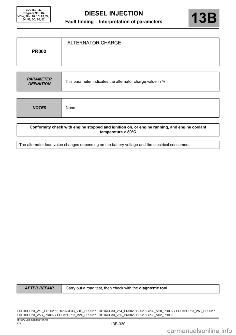
PR002ALTERNATOR CHARGE
PARAMETER
DEFINITIONThis parameter indicates the alternator charge value in %.
NOTESNone.
Conformity check with engine stopped and ignition on, or engine running, and engine coolant
temperature > 80°C
The alternator load value changes depending on the battery voltage and the electrical consumers.
EDC16CP33_V18_PR002 / EDC16CP33_V1C_PR002 / EDC16CP33_V54_PR002 / EDC16CP33_V20_PR002 / EDC16CP33_V58_PR002 /
EDC16CP33_V5C_PR002 / EDC16CP33_V24_PR002 / EDC16CP33_V60_PR002 / EDC16CP33_V62_PR002
DIESEL INJECTION
Fault finding – Interpretation of parameters
EDC16CP33
Program No.: C4
VDiag No.: 18, 1C, 20, 24,
54, 58, 5C, 60, 62
Page 484 of 510
13B-484
AFTER REPAIRCarry out a road test, then check with the diagnostic tool.
V12 MR-372-J84-13B300$170.mif
DIESEL INJECTION
Fault finding – Fault Finding Chart13B
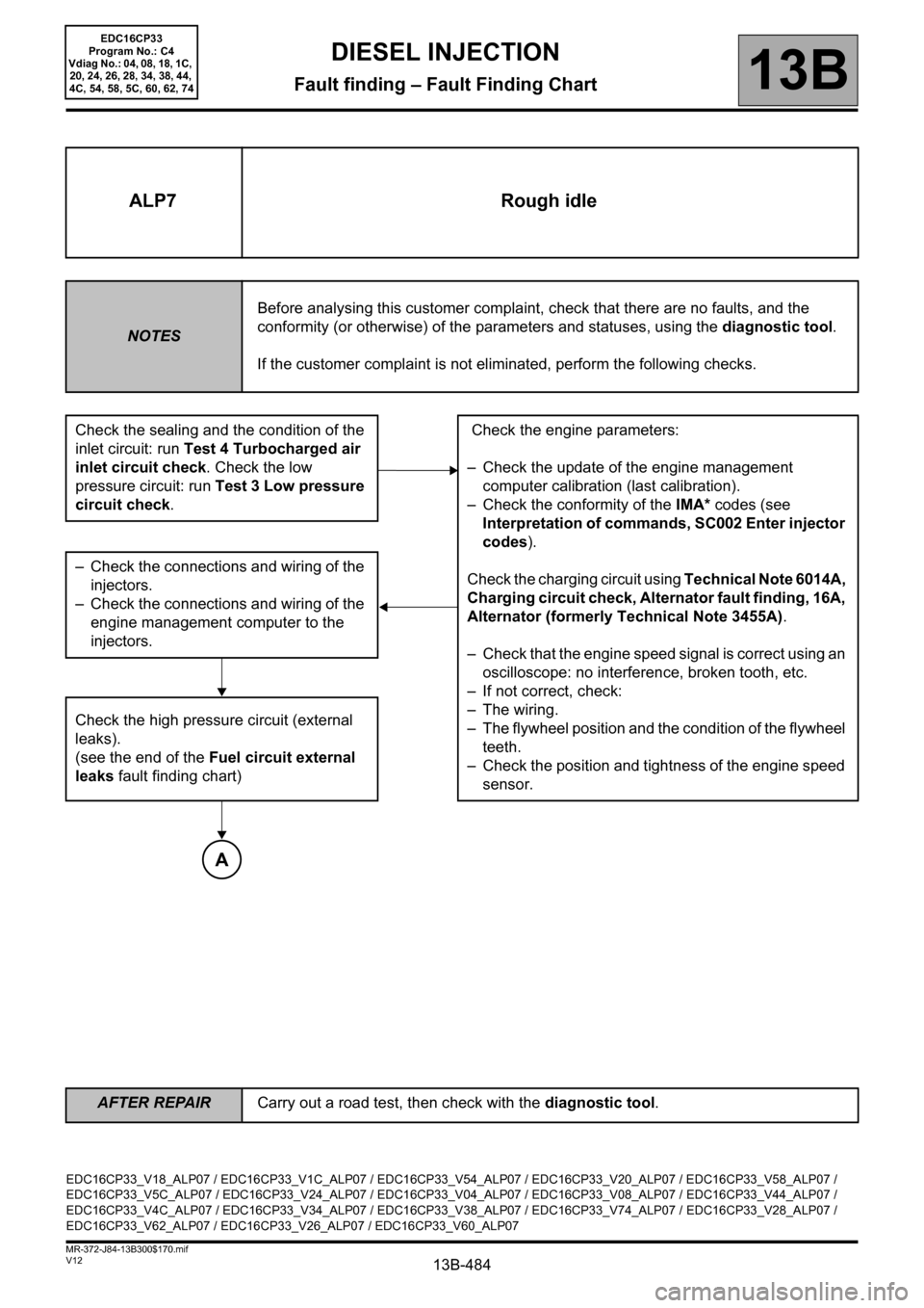
ALP7 Rough idle
NOTESBefore analysing this customer complaint, check that there are no faults, and the
conformity (or otherwise) of the parameters and statuses, using the diagnostic tool.
If the customer complaint is not eliminated, perform the following checks.
Check the sealing and the condition of the
inlet circuit: run Test 4 Turbocharged air
inlet circuit check. Check the low
pressure circuit: run Test 3 Low pressure
circuit check. Check the engine parameters:
– Check the update of the engine management
computer calibration (last calibration).
– Check the conformity of the IMA* codes (see
Interpretation of commands, SC002 Enter injector
codes).
Check the charging circuit using Technical Note 6014A,
Charging circuit check, Alternator fault finding, 16A,
Alternator (formerly Technical Note 3455A).
– Check that the engine speed signal is correct using an
oscilloscope: no interference, broken tooth, etc.
– If not correct, check:
– The wiring.
– The flywheel position and the condition of the flywheel
teeth.
– Check the position and tightness of the engine speed
sensor. – Check the connections and wiring of the
injectors.
– Check the connections and wiring of the
engine management computer to the
injectors.
Check the high pressure circuit (external
leaks).
(see the end of the Fuel circuit external
leaks fault finding chart)
A
EDC16CP33_V18_ALP07 / EDC16CP33_V1C_ALP07 / EDC16CP33_V54_ALP07 / EDC16CP33_V20_ALP07 / EDC16CP33_V58_ALP07 /
EDC16CP33_V5C_ALP07 / EDC16CP33_V24_ALP07 / EDC16CP33_V04_ALP07 / EDC16CP33_V08_ALP07 / EDC16CP33_V44_ALP07 /
EDC16CP33_V4C_ALP07 / EDC16CP33_V34_ALP07 / EDC16CP33_V38_ALP07 / EDC16CP33_V74_ALP07 / EDC16CP33_V28_ALP07 /
EDC16CP33_V62_ALP07 / EDC16CP33_V26_ALP07 / EDC16CP33_V60_ALP07
EDC16CP33
Program No.: C4
Vdiag No.: 04, 08, 18, 1C,
20, 24, 26, 28, 34, 38, 44,
4C, 54, 58, 5C, 60, 62, 74