check engine RENAULT SCENIC 2014 J95 / 3.G Petrol Injection - Sagem3000 Owner's Guide
[x] Cancel search | Manufacturer: RENAULT, Model Year: 2014, Model line: SCENIC, Model: RENAULT SCENIC 2014 J95 / 3.GPages: 181
Page 62 of 181
PETROL INJECTION
Fault finding – Interpretation of faults17B
17B-62V12 MR-372-J84-17B000$360.mif
SAGEM 3000
Program No.: A7
Vdiag No.: 44, 48
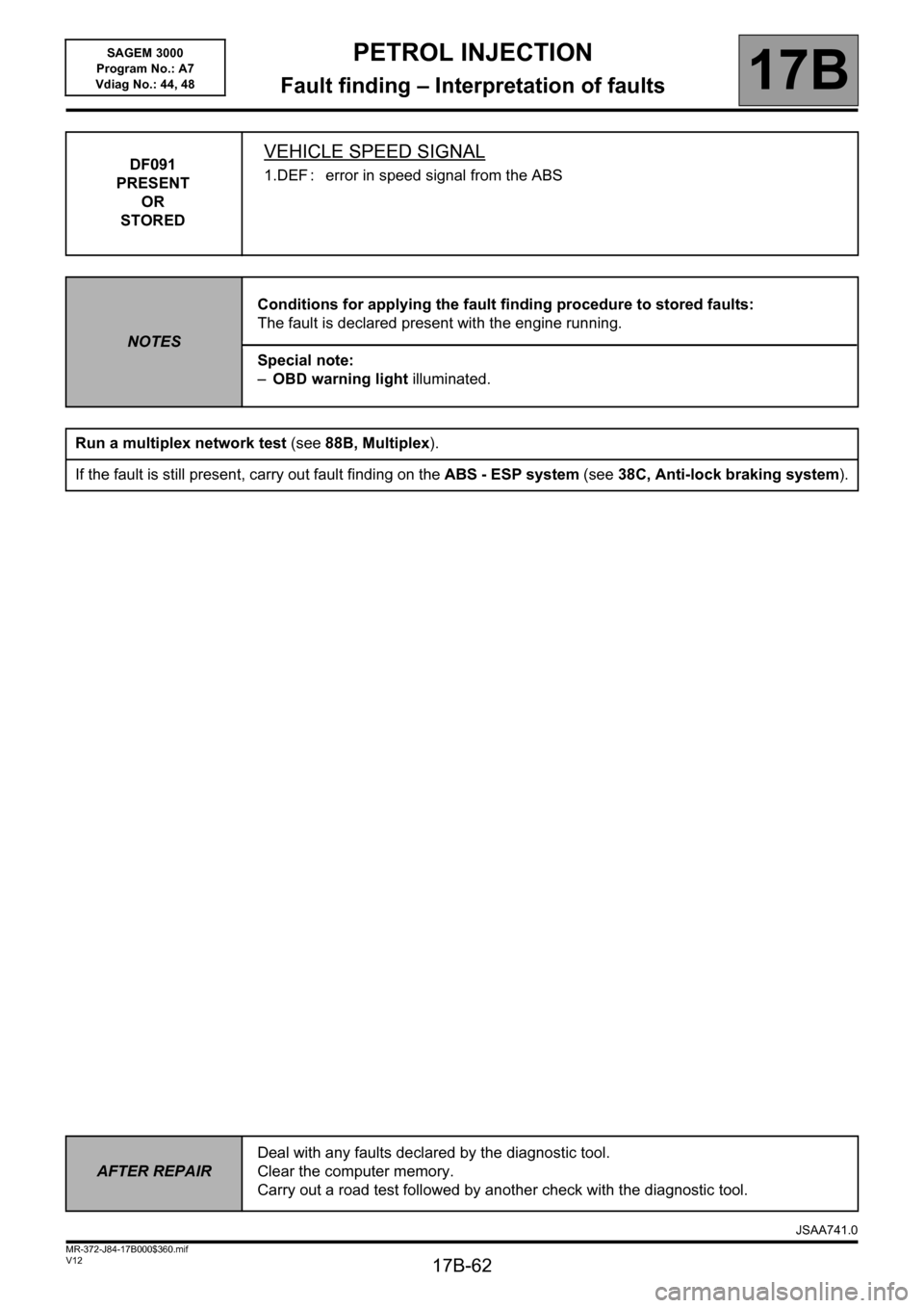
DF091
PRESENT
OR
STOREDVEHICLE SPEED SIGNAL
1.DEF : error in speed signal from the ABS
NOTESConditions for applying the fault finding procedure to stored faults:
The fault is declared present with the engine running.
Special note:
–OBD warning light illuminated.
Run a multiplex network test (see88B, Multiplex).
If the fault is still present, carry out fault finding on the ABS - ESP system (see38C, Anti-lock braking system).
AFTER REPAIRDeal with any faults declared by the diagnostic tool.
Clear the computer memory.
Carry out a road test followed by another check with the diagnostic tool.
JSAA741.0
Page 63 of 181
PETROL INJECTION
Fault finding – Interpretation of faults17B
17B-63V12 MR-372-J84-17B000$360.mif
SAGEM 3000
Program No.: A7
Vdiag No.: 44, 48
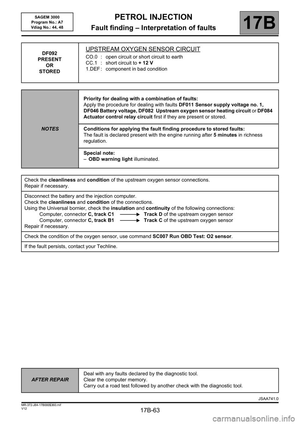
DF092
PRESENT
OR
STOREDUPSTREAM OXYGEN SENSOR CIRCUIT
CO.0 : open circuit or short circuit to earth
CC.1 : short circuit to + 12 V
1.DEF : component in bad condition
NOTESPriority for dealing with a combination of faults:
Apply the procedure for dealing with faults DF011 Sensor supply voltage no. 1,
DF046 Battery voltage, DF082 Upstream oxygen sensor heating circuit or DF084
Actuator control relay circuit first if they are present or stored.
Conditions for applying the fault finding procedure to stored faults:
The fault is declared present with the engine running after 5 minutes in richness
regulation.
Special note:
–OBD warning light illuminated.
Check the cleanliness and condition of the upstream oxygen sensor connections.
Repair if necessary.
Disconnect the battery and the injection computer.
Check the cleanliness and condition of the connections.
Using the Universal bornier, check the insulation and continuity of the following connections:
Computer, connectorC, track C1 Track D of the upstream oxygen sensor
Computer, connectorC, track B1 Track C of the upstream oxygen sensor
Repair if necessary.
Check the condition of the oxygen sensor, use command SC007 Run OBD Test: O2 sensor.
If the fault persists, contact your Techline.
AFTER REPAIRDeal with any faults declared by the diagnostic tool.
Clear the computer memory.
Carry out a road test followed by another check with the diagnostic tool.
JSAA741.0
Page 65 of 181
PETROL INJECTION
Fault finding – Interpretation of faults17B
17B-65V12 MR-372-J84-17B000$360.mif
SAGEM 3000
Program No.: A7
Vdiag No.: 44, 48
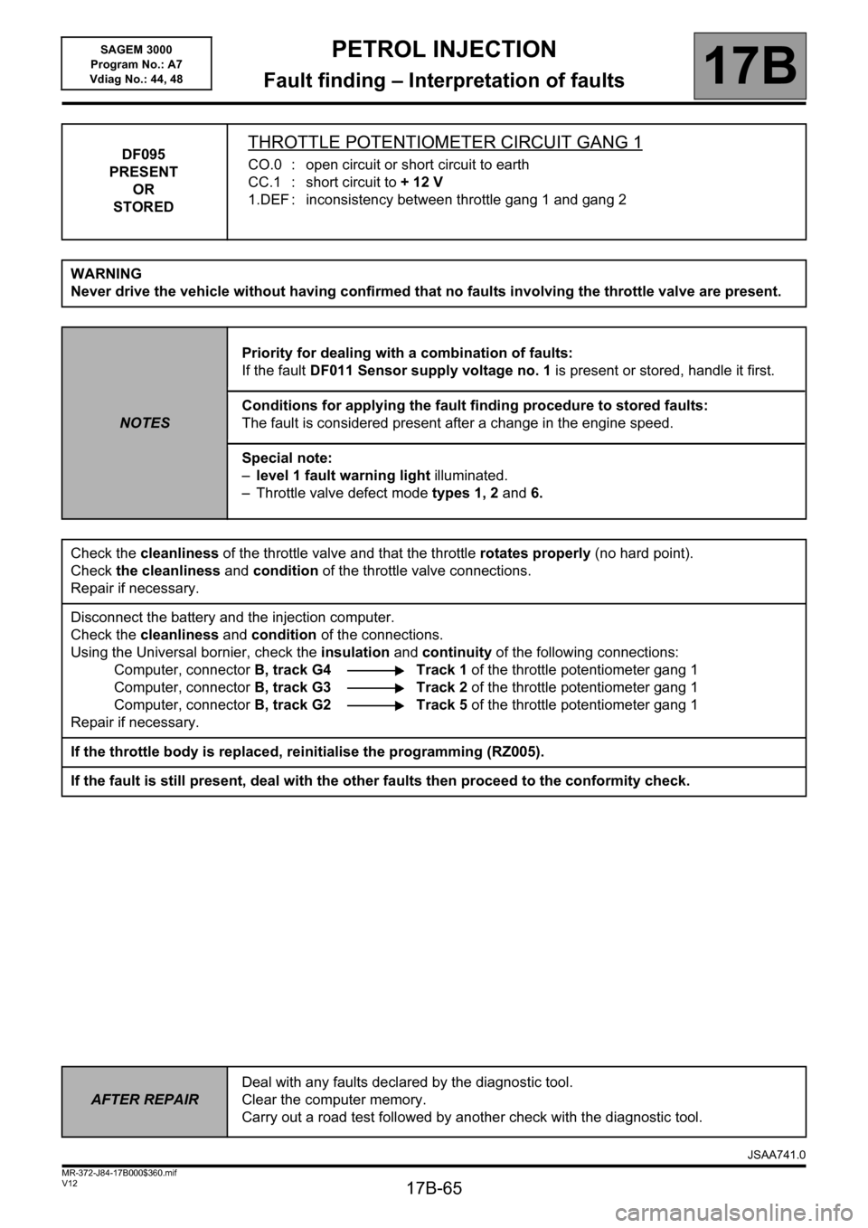
DF095
PRESENT
OR
STOREDTHROTTLE POTENTIOMETER CIRCUIT GANG 1
CO.0 : open circuit or short circuit to earth
CC.1 : short circuit to + 12 V
1.DEF : inconsistency between throttle gang 1 and gang 2
WARNING
Never drive the vehicle without having confirmed that no faults involving the throttle valve are present.
NOTESPriority for dealing with a combination of faults:
If the fault DF011 Sensor supply voltage no. 1 is present or stored, handle it first.
Conditions for applying the fault finding procedure to stored faults:
The fault is considered present after a change in the engine speed.
Special note:
–level 1 fault warning light illuminated.
– Throttle valve defect mode types 1, 2 and 6.
Check the cleanliness of the throttle valve and that the throttle rotates properly (no hard point).
Check the cleanliness and condition of the throttle valve connections.
Repair if necessary.
Disconnect the battery and the injection computer.
Check the cleanliness and condition of the connections.
Using the Universal bornier, check the insulation and continuity of the following connections:
Computer, connectorB, track G4 Track 1 of the throttle potentiometer gang 1
Computer, connectorB, track G3 Track 2 of the throttle potentiometer gang 1
Computer, connectorB, track G2 Track 5 of the throttle potentiometer gang 1
Repair if necessary.
If the throttle body is replaced, reinitialise the programming (RZ005).
If the fault is still present, deal with the other faults then proceed to the conformity check.
AFTER REPAIRDeal with any faults declared by the diagnostic tool.
Clear the computer memory.
Carry out a road test followed by another check with the diagnostic tool.
JSAA741.0
Page 66 of 181
PETROL INJECTION
Fault finding – Interpretation of faults17B
17B-66V12 MR-372-J84-17B000$360.mif
SAGEM 3000
Program No.: A7
Vdiag No.: 44, 48
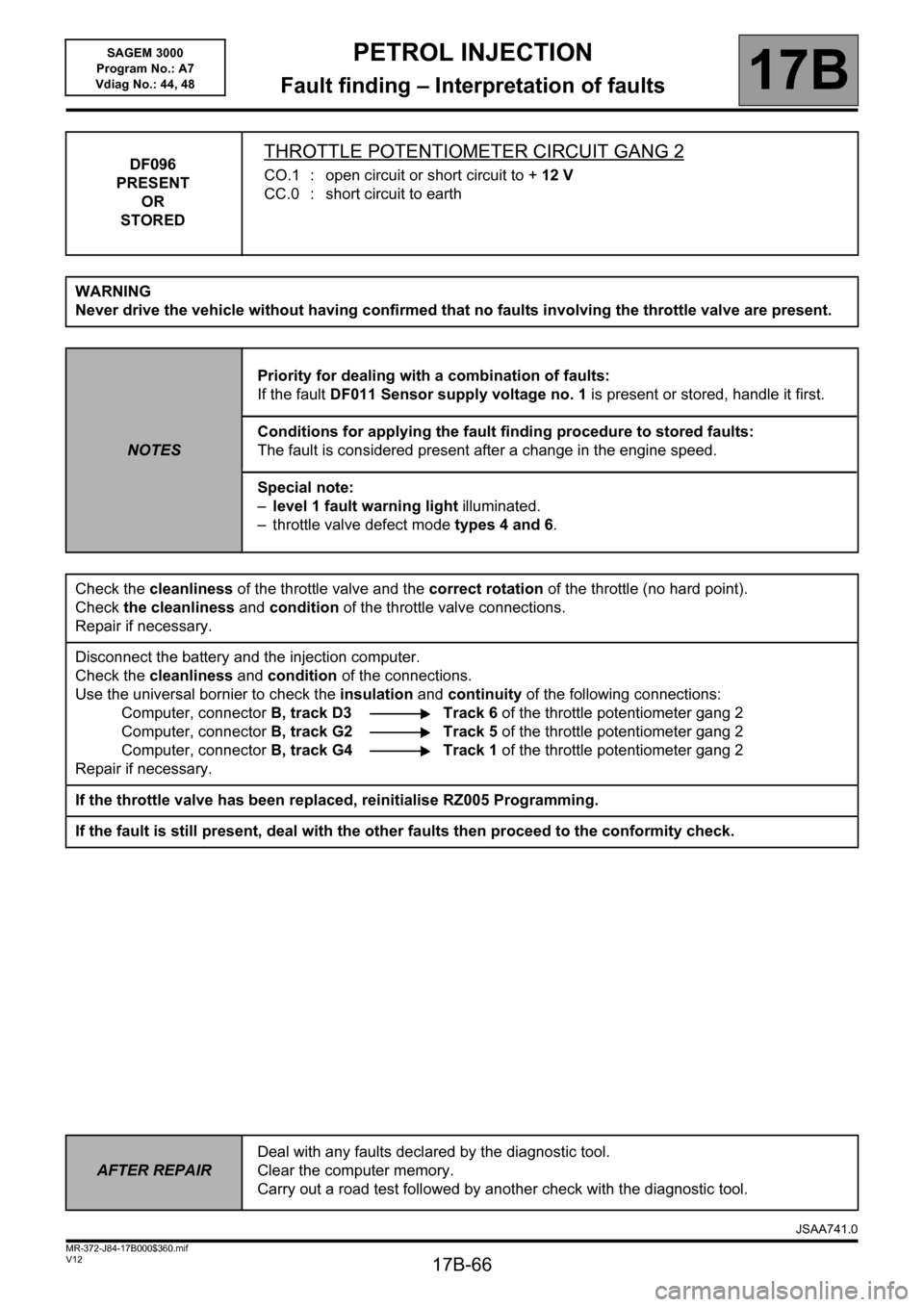
DF096
PRESENT
OR
STOREDTHROTTLE POTENTIOMETER CIRCUIT GANG 2
CO.1 : open circuit or short circuit to +12 V
CC.0 : short circuit to earth
WARNING
Never drive the vehicle without having confirmed that no faults involving the throttle valve are present.
NOTESPriority for dealing with a combination of faults:
If the fault DF011 Sensor supply voltage no. 1 is present or stored, handle it first.
Conditions for applying the fault finding procedure to stored faults:
The fault is considered present after a change in the engine speed.
Special note:
–level 1 fault warning light illuminated.
– throttle valve defect mode types 4 and 6.
Check the cleanliness of the throttle valve and the correct rotation of the throttle (no hard point).
Check the cleanliness and condition of the throttle valve connections.
Repair if necessary.
Disconnect the battery and the injection computer.
Check the cleanliness and condition of the connections.
Use the universal bornier to check the insulation and continuity of the following connections:
Computer, connector B, track D3 Track 6 of the throttle potentiometer gang 2
Computer, connectorB, track G2 Track 5 of the throttle potentiometer gang 2
Computer, connectorB, track G4 Track 1 of the throttle potentiometer gang 2
Repair if necessary.
If the throttle valve has been replaced, reinitialise RZ005 Programming.
If the fault is still present, deal with the other faults then proceed to the conformity check.
AFTER REPAIRDeal with any faults declared by the diagnostic tool.
Clear the computer memory.
Carry out a road test followed by another check with the diagnostic tool.
JSAA741.0
Page 68 of 181
PETROL INJECTION
Fault finding – Interpretation of faults17B
17B-68V12 MR-372-J84-17B000$360.mif
SAGEM 3000
Program No.: A7
Vdiag No.: 44, 48
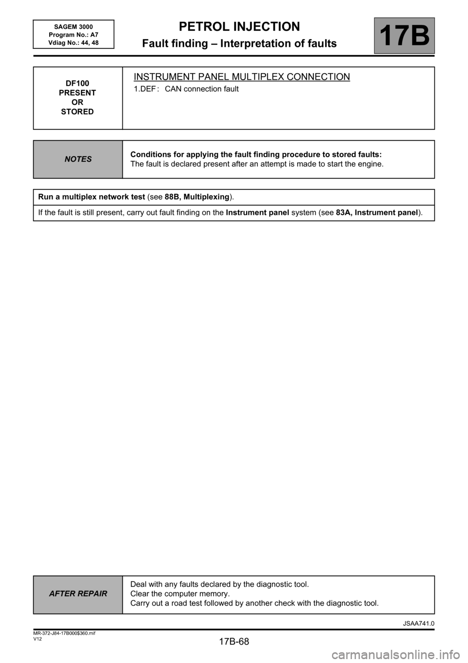
DF100
PRESENT
OR
STOREDINSTRUMENT PANEL MULTIPLEX CONNECTION
1.DEF : CAN connection fault
NOTESConditions for applying the fault finding procedure to stored faults:
The fault is declared present after an attempt is made to start the engine.
Run a multiplex network test (see88B, Multiplexing).
If the fault is still present, carry out fault finding on the Instrument panel system (see83A, Instrument panel).
AFTER REPAIRDeal with any faults declared by the diagnostic tool.
Clear the computer memory.
Carry out a road test followed by another check with the diagnostic tool.
JSAA741.0
Page 69 of 181
PETROL INJECTION
Fault finding – Interpretation of faults17B
17B-69V12 MR-372-J84-17B000$360.mif
SAGEM 3000
Program No.: A7
Vdiag No.: 44, 48
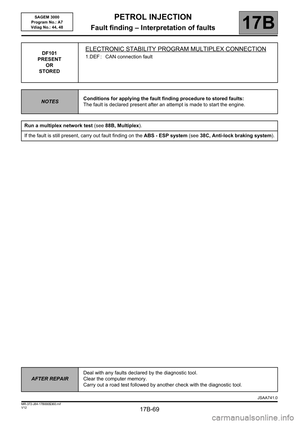
DF101
PRESENT
OR
STOREDELECTRONIC STABILITY PROGRAM MULTIPLEX CONNECTION
1.DEF : CAN connection fault
NOTESConditions for applying the fault finding procedure to stored faults:
The fault is declared present after an attempt is made to start the engine.
Run a multiplex network test (see88B, Multiplex).
If the fault is still present, carry out fault finding on the ABS - ESP system (see38C, Anti-lock braking system).
AFTER REPAIRDeal with any faults declared by the diagnostic tool.
Clear the computer memory.
Carry out a road test followed by another check with the diagnostic tool.
JSAA741.0
Page 73 of 181
PETROL INJECTION
Fault finding – Interpretation of faults17B
17B-73V12 MR-372-J84-17B000$360.mif
SAGEM 3000
Program No.: A7
Vdiag No.: 44, 48
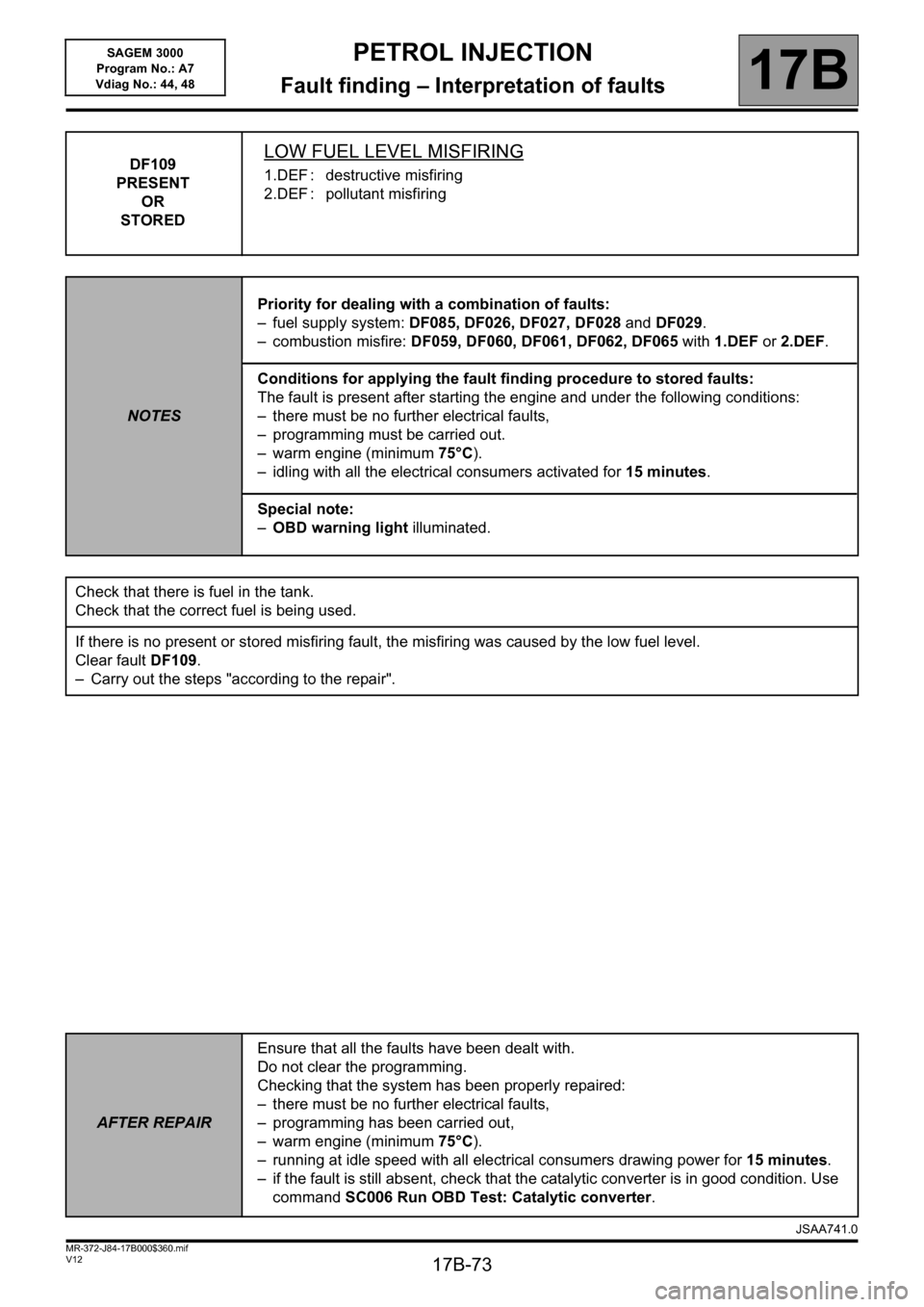
DF109
PRESENT
OR
STOREDLOW FUEL LEVEL MISFIRING
1.DEF : destructive misfiring
2.DEF : pollutant misfiring
NOTESPriority for dealing with a combination of faults:
– fuel supply system: DF085, DF026, DF027, DF028 and DF029.
– combustion misfire: DF059, DF060, DF061, DF062, DF065 with 1.DEF or 2.DEF.
Conditions for applying the fault finding procedure to stored faults:
The fault is present after starting the engine and under the following conditions:
– there must be no further electrical faults,
– programming must be carried out.
– warm engine (minimum 75°C).
– idling with all the electrical consumers activated for 15 minutes.
Special note:
–OBD warning light illuminated.
Check that there is fuel in the tank.
Check that the correct fuel is being used.
If there is no present or stored misfiring fault, the misfiring was caused by the low fuel level.
Clear fault DF109.
– Carry out the steps "according to the repair".
AFTER REPAIREnsure that all the faults have been dealt with.
Do not clear the programming.
Checking that the system has been properly repaired:
– there must be no further electrical faults,
– programming has been carried out,
– warm engine (minimum 75°C).
– running at idle speed with all electrical consumers drawing power for 15 minutes.
– if the fault is still absent, check that the catalytic converter is in good condition. Use
command SC006 Run OBD Test: Catalytic converter.
JSAA741.0
Page 74 of 181
PETROL INJECTION
Fault finding – Interpretation of faults17B
17B-74V12 MR-372-J84-17B000$360.mif
SAGEM 3000
Program No.: A7
Vdiag No.: 44, 48
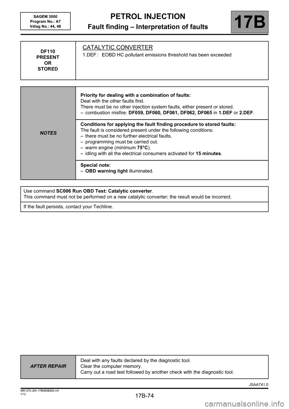
DF110
PRESENT
OR
STOREDCATALYTIC CONVERTER
1.DEF : EOBD HC pollutant emissions threshold has been exceeded
NOTESPriority for dealing with a combination of faults:
Deal with the other faults first.
There must be no other injection system faults, either present or stored.
– combustion misfire: DF059, DF060, DF061, DF062, DF065 in 1.DEF or 2.DEF.
Conditions for applying the fault finding procedure to stored faults:
The fault is considered present under the following conditions:
– there must be no further electrical faults,
– programming must be carried out.
– warm engine (minimum 75°C).
– idling with all the electrical consumers activated for 15 minutes.
Special note:
–OBD warning light illuminated.
Use command SC006 Run OBD Test: Catalytic converter.
This command must not be performed on a new catalytic converter; the result would be incorrect.
If the fault persists, contact your Techline.
AFTER REPAIRDeal with any faults declared by the diagnostic tool.
Clear the computer memory.
Carry out a road test followed by another check with the diagnostic tool.
JSAA741.0
Page 76 of 181
PETROL INJECTION
Fault finding – Interpretation of faults17B
17B-76V12 MR-372-J84-17B000$360.mif
SAGEM 3000
Program No.: A7
Vdiag No.: 44, 48
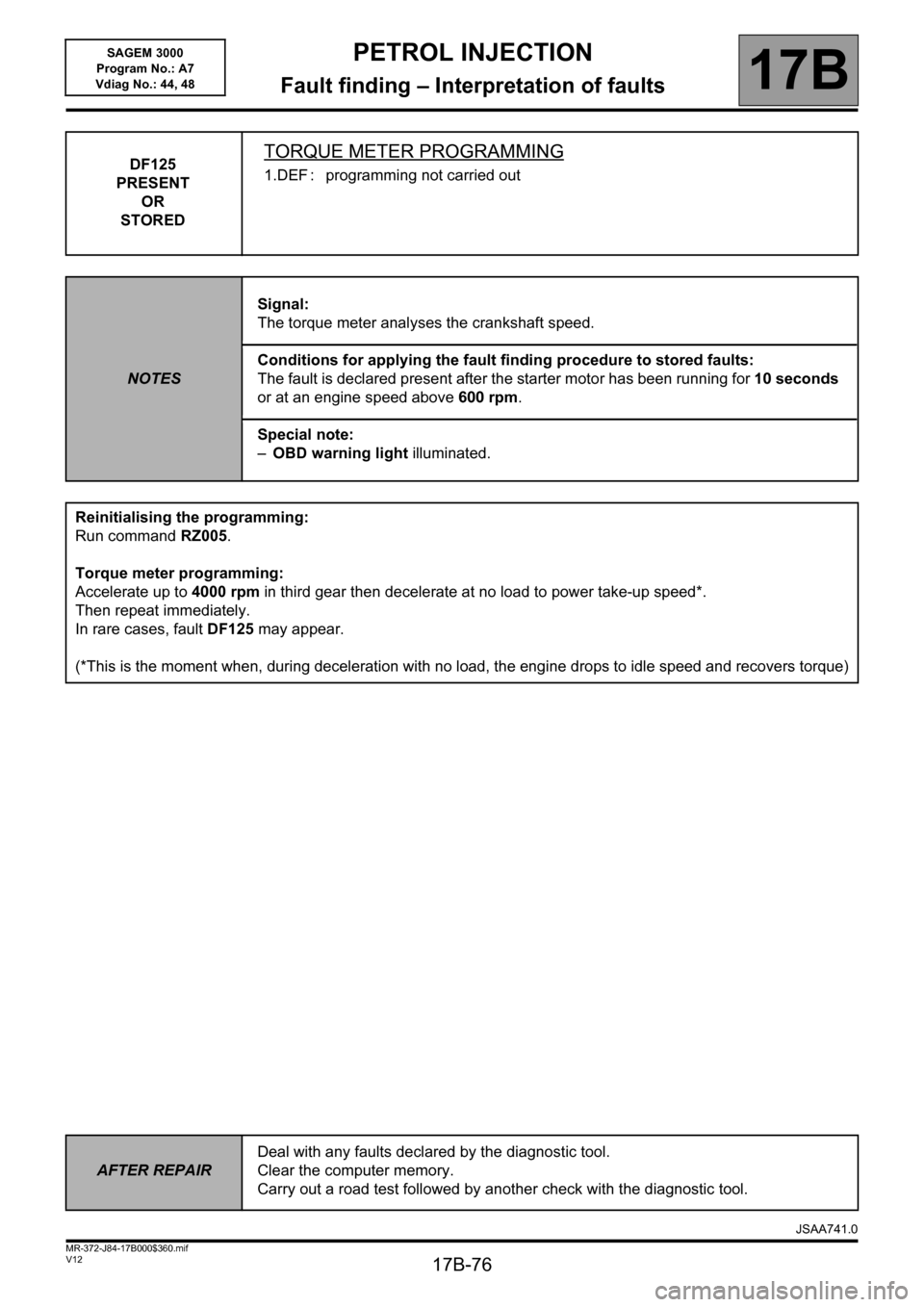
DF125
PRESENT
OR
STOREDTORQUE METER PROGRAMMING
1.DEF : programming not carried out
NOTESSignal:
The torque meter analyses the crankshaft speed.
Conditions for applying the fault finding procedure to stored faults:
The fault is declared present after the starter motor has been running for 10 seconds
or at an engine speed above 600 rpm.
Special note:
–OBD warning light illuminated.
Reinitialising the programming:
Run command RZ005.
Torque meter programming:
Accelerate up to 4000 rpm in third gear then decelerate at no load to power take-up speed*.
Then repeat immediately.
In rare cases, fault DF125 may appear.
(*This is the moment when, during deceleration with no load, the engine drops to idle speed and recovers torque)
AFTER REPAIRDeal with any faults declared by the diagnostic tool.
Clear the computer memory.
Carry out a road test followed by another check with the diagnostic tool.
JSAA741.0
Page 77 of 181
PETROL INJECTION
Fault finding – Interpretation of faults17B
17B-77V12 MR-372-J84-17B000$360.mif
SAGEM 3000
Program No.: A7
Vdiag No.: 44, 48
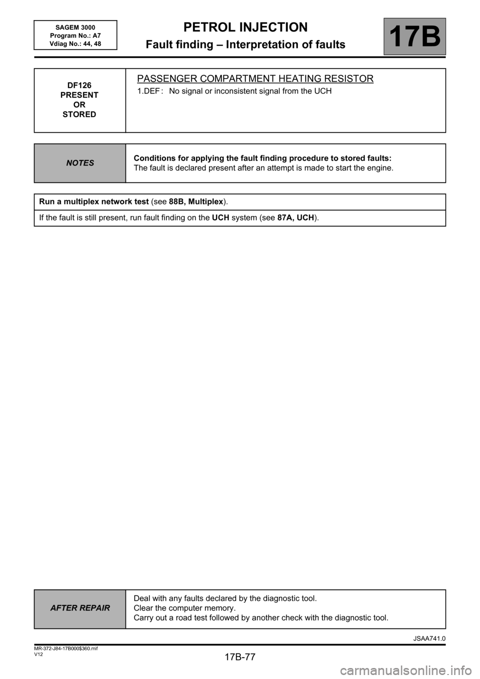
DF126
PRESENT
OR
STOREDPASSENGER COMPARTMENT HEATING RESISTOR
1.DEF : No signal or inconsistent signal from the UCH
NOTESConditions for applying the fault finding procedure to stored faults:
The fault is declared present after an attempt is made to start the engine.
Run a multiplex network test (see88B, Multiplex).
If the fault is still present, run fault finding on the UCH system (see87A, UCH).
AFTER REPAIRDeal with any faults declared by the diagnostic tool.
Clear the computer memory.
Carry out a road test followed by another check with the diagnostic tool.
JSAA741.0