programming RENAULT SCENIC 2014 J95 / 3.G Petrol Injection - Sagem3000 Workshop Manual
[x] Cancel search | Manufacturer: RENAULT, Model Year: 2014, Model line: SCENIC, Model: RENAULT SCENIC 2014 J95 / 3.GPages: 181
Page 1 of 181
1Engine and peripherals
V12 MR-372-J84-17B000$TOC.mif
V12
17B
"The repair procedures given by the manufacturer in this document are based on the
technical specifications current when it was prepared.
The procedures may be modified as a result of changes introduced by the
manufacturer in the production of the various component units and accessories from
which his vehicles are constructed."
V12
All rights reserved by Renault s.a.s.
Edition Anglaise
Copying or translating, in part or in full, of this document or use of the service part
reference numbering system is forbidden without the prior written authority of
Renault s.a.s.
© Renault s.a.s. 2014
PETROL INJECTION
SAGEM 3000
Program No.: A7
Vdiag No.: 44, 48
Fault finding – Introduction 17B - 2
Fault finding – System operation 17B - 7
Fault finding – Allocation of computer tracks 17B - 12
Fault finding – Replacement of components 17B - 15
Fault finding – Configurations and programming 17B - 16
Fault finding – Fault summary table 17B - 17
Fault finding – Interpretation of faults 17B - 21
Fault finding – Conformity check 17B - 90
Fault finding – Status summary table 17B - 132
Fault finding – Interpretation of statuses 17B - 134
Fault finding – Parameter summary table 17B - 156
Fault finding – Interpretation of parameters 17B - 158
Fault finding – Command summary table 17B - 166
Fault finding – Interpretation of commands 17B - 167
Fault finding – Help 17B - 173
Fault finding – Customer complaints 17B - 175
Fault finding – Fault Finding Chart 17B - 176
Page 12 of 181

PETROL INJECTION
Fault finding – Allocation of computer tracks17B
17B - 12V12 MR-372-J84-17B000$135.mif
SAGEM 3000
Program No.: A7
Vdiag No.: 44, 48PETROL INJECTION
Fault finding – Allocation of computer tracks
Connector (A), 32 tracks:
Track Description
A1
A2
A3
A4
B1
B2
B3
B4
C1
C2
C3
C4
D1
D2
D3
D4
E1
E2
E3
E4
F1
F2
F3
F4
G1
G2
G3
G4
H1
H2
H3
H4Not used
Cruise control on/off switch
Engine CAN LOW multiplex connection
Engine CAN HIGH multiplex connection
Not used
Not used
Not used
K-line diagnostics
Not used
Not used
Speed limiter on/off switch
+ Clutch switch signal
+ after ignition feed via UPC
Cruise control/speed limiter controls supply
Cruise control programming feedback signal
Not used
Not used
Not used
Not used
Brake pedal switch signal
Not used
Accelerator pedal potentiometer gang 2 + 5 V feed
Accelerator pedal potentiometer signal, gang 2
Accelerator pedal potentiometer earth, gang 2
Battery + feed via the UPC
Accelerator pedal potentiometer gang 1 + 5 V feed
Not used
Electronic earth
Electronic earth
Accelerator pedal potentiometer signal, gang 1
Accelerator pedal potentiometer earth, gang 1
Electronic earth
JSAA741.0
MR-372-J84-17B000$135.mif
Page 15 of 181

PETROL INJECTION
Fault finding – Replacement of components17B
17B - 15V12 MR-372-J84-17B000$180.mif
SAGEM 3000
Program No.: A7
Vdiag No.: 44, 48PETROL INJECTION
Fault finding – Replacement of components
1. PROGRAMMING, REPROGRAMMING OR REPLACING THE COMPUTER
The system can be programmed and reprogrammed via the diagnostic socket using the RENAULT CLIP diagnostic
tool (Consult Technical Note 3585A or follow the instructions provided by the diagnostic tool).
Whenever the computer has been programmed, reprogrammed or replaced:
–switch off the ignition;
–start and then stop the engine (to initialise the computer) and wait for 30 seconds,
–switch on the ignition again and use the diagnostic tool to carry out the following steps:
– run command VP010 Enter VIN,
– deal with any faults declared by the diagnostic tool. Clear the computer memory.
– program the flywheel sensor target and throttle stops,
– carry out a road test followed by another check with the diagnostic tool.
2. REPLACING OR REMOVING THE TDC SENSOR
When the TDC sensor is replaced or removed, the flywheel target has to be programmed.
3. REPLACING THE MOTORISED THROTTLE VALVE
When the throttle valve is replaced, the throttle stops must be programmed.IMPORTANT
–switch on the diagnostic tool (mains or cigarette lighter supply),
–connect a battery charger (during the entire computer (re)programming procedure, the motor-driven fan
assemblies are triggered automatically),
–observe the engine temperature instructions of the diagnostic tool before (re)programming.
IMPORTANT
It is not possible to test an injection computer from the Parts Department because it can no longer be fitted on any
other vehicle.
IMPORTANT
Never drive the vehicle without having programmed the throttle stops.
JSAA741.0
MR-372-J84-17B000$180.mif
Page 16 of 181

PETROL INJECTION
Fault finding – Configurations and programming17B
17B - 16V12 MR-372-J84-17B000$225.mif
SAGEM 3000
Program No.: A7
Vdiag No.: 44, 48PETROL INJECTION
Fault finding – Configurations and programming
1. CONFIGURATION
Computer configuration by automatic detection
The computer can automatically configure itself based on the sensors or vehicle options it detects.
2. PROGRAMMING
Programming the flywheel target
Accelerate up to 4000 rpm in 3rd gear then decelerate to power take-up* speed. Then repeat immediately.
Check the programming with ET089.
Programming the throttle end stops
After replacing the computer or motorised throttle valve, after switching on the ignition, wait 30 seconds for the
computer to memorise the MAXIMUM and MINIMUM stops.
Check the programming with ET051.
* This is the moment when, during deceleration with no load, the engine drops to idle speed and recovers torque.
JSAA741.0
MR-372-J84-17B000$225.mif
Page 20 of 181

PETROL INJECTION
Fault finding – Fault summary table17B
17B - 20V12 MR-372-J84-17B000$270.mif
SAGEM 3000
Program No.: A7
Vdiag No.: 44, 48
Tool
faultsHexadecimal
DTC codesDescriptionLevel 1 fault
warning lightNo warning
light onOBD warning
light
DF1090313 Low fuel level misfire 1.DEF/2.DEF
DF1100420 Catalytic converter 1.DEF
DF1190340 Camshaft sensor signal
DF1250314Torque sensor
programming1.DEF
DF1261604Passenger
compartment heating
resistor (RCH)1.DEF
DF1270703Brake switch no. 1
circuit1.DEF
DF1280571 Brake switch 2 circuit 1.DEF
DF1540335Flywheel signal sensor
circuit1.DEF/2.DEF
DF3980170Fuel circuit operating
fault1.DEF
DF4550460 Low fuel level signal 1.DEF
DF6080830 Clutch pedal switch 1.DEF
DF6121605Oil vapour anti-icing
resistor circuitCO.0
DF6351301LPG cylinder 1
combustion misfire1.DEF/2.DEF
DF6361302LPG cylinder 2
combustion misfire1.DEF/2.DEF
DF6371303LPG cylinder 3
combustion misfire1.DEF/2.DEF
DF6381304LPG cylinder 4
combustion misfire1.DEF/2.DEF
DF6391300Combustion misfire in
LPG mode1.DEF/2.DEF/
3.DEF
JSAA741.0
Page 37 of 181
PETROL INJECTION
Fault finding – Interpretation of faults17B
17B-37V12 MR-372-J84-17B000$315.mif
SAGEM 3000
Program No.: A7
Vdiag No.: 44, 48
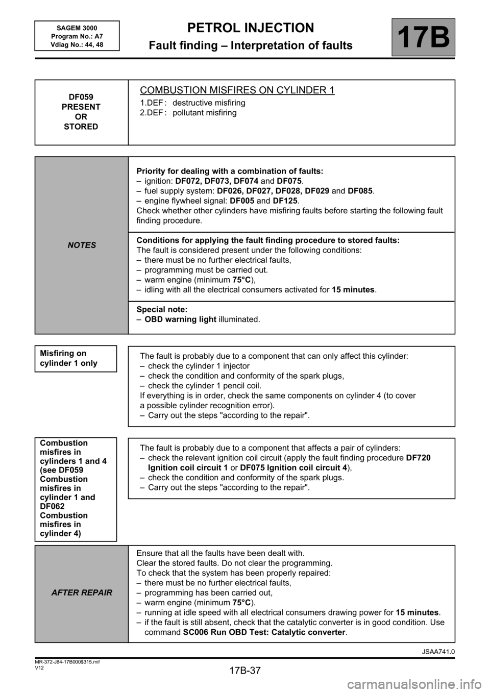
DF059
PRESENT
OR
STOREDCOMBUSTION MISFIRES ON CYLINDER 1
1.DEF : destructive misfiring
2.DEF : pollutant misfiring
NOTESPriority for dealing with a combination of faults:
– ignition: DF072, DF073, DF074 and DF075.
– fuel supply system: DF026, DF027, DF028, DF029 and DF085.
– engine flywheel signal: DF005 and DF125.
Check whether other cylinders have misfiring faults before starting the following fault
finding procedure.
Conditions for applying the fault finding procedure to stored faults:
The fault is considered present under the following conditions:
– there must be no further electrical faults,
– programming must be carried out.
– warm engine (minimum 75°C),
– idling with all the electrical consumers activated for 15 minutes.
Special note:
–OBD warning light illuminated.
Misfiring on
cylinder 1 only
Combustion
misfires in
cylinders 1 and 4
(see DF059
Combustion
misfires in
cylinder 1 and
DF062
Combustion
misfires in
cylinder 4)
The fault is probably due to a component that can only affect this cylinder:
– check the cylinder 1 injector
– check the condition and conformity of the spark plugs,
– check the cylinder 1 pencil coil.
If everything is in order, check the same components on cylinder 4 (to cover
a possible cylinder recognition error).
– Carry out the steps "according to the repair".
The fault is probably due to a component that affects a pair of cylinders:
– check the relevant ignition coil circuit (apply the fault finding procedure DF720
Ignition coil circuit 1 or DF075 Ignition coil circuit 4),
– check the condition and conformity of the spark plugs.
– Carry out the steps "according to the repair".
AFTER REPAIREnsure that all the faults have been dealt with.
Clear the stored faults. Do not clear the programming.
To check that the system has been properly repaired:
– there must be no further electrical faults,
– programming has been carried out,
– warm engine (minimum 75°C).
– running at idle speed with all electrical consumers drawing power for 15 minutes.
– if the fault is still absent, check that the catalytic converter is in good condition. Use
command SC006 Run OBD Test: Catalytic converter.
JSAA741.0
Page 38 of 181
PETROL INJECTION
Fault finding – Interpretation of faults17B
17B-38V12 MR-372-J84-17B000$315.mif
SAGEM 3000
Program No.: A7
Vdiag No.: 44, 48
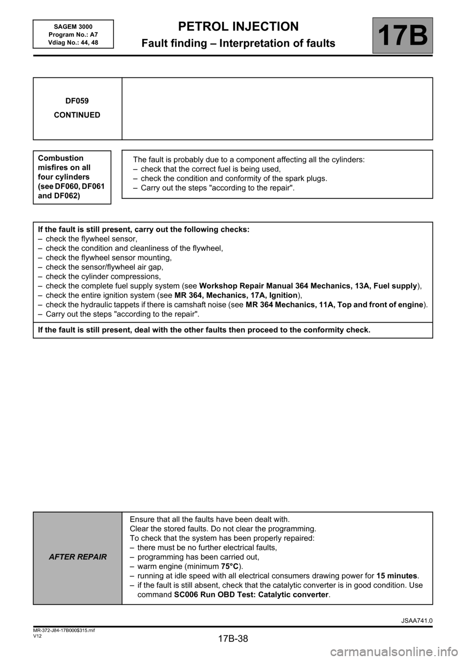
DF059
CONTINUED
Combustion
misfires on all
four cylinders
(see DF060, DF061
and DF062)
The fault is probably due to a component affecting all the cylinders:
– check that the correct fuel is being used,
– check the condition and conformity of the spark plugs.
– Carry out the steps "according to the repair".
If the fault is still present, carry out the following checks:
– check the flywheel sensor,
– check the condition and cleanliness of the flywheel,
– check the flywheel sensor mounting,
– check the sensor/flywheel air gap,
– check the cylinder compressions,
– check the complete fuel supply system (see Workshop Repair Manual 364 Mechanics, 13A, Fuel supply),
– check the entire ignition system (see MR 364, Mechanics, 17A, Ignition),
– check the hydraulic tappets if there is camshaft noise (seeMR 364 Mechanics, 11A, Top and front of engine).
– Carry out the steps "according to the repair".
If the fault is still present, deal with the other faults then proceed to the conformity check.
AFTER REPAIREnsure that all the faults have been dealt with.
Clear the stored faults. Do not clear the programming.
To check that the system has been properly repaired:
– there must be no further electrical faults,
– programming has been carried out,
– warm engine (minimum 75°C).
– running at idle speed with all electrical consumers drawing power for 15 minutes.
– if the fault is still absent, check that the catalytic converter is in good condition. Use
command SC006 Run OBD Test: Catalytic converter.
JSAA741.0
Page 39 of 181
PETROL INJECTION
Fault finding – Interpretation of faults17B
17B-39V12 MR-372-J84-17B000$315.mif
SAGEM 3000
Program No.: A7
Vdiag No.: 44, 48
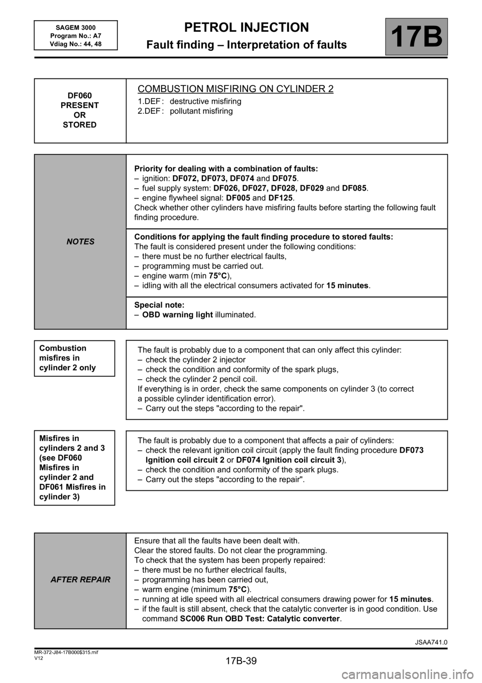
DF060
PRESENT
OR
STOREDCOMBUSTION MISFIRING ON CYLINDER 2
1.DEF : destructive misfiring
2.DEF : pollutant misfiring
NOTESPriority for dealing with a combination of faults:
– ignition: DF072, DF073, DF074 and DF075.
– fuel supply system: DF026, DF027, DF028, DF029 and DF085.
– engine flywheel signal: DF005 and DF125.
Check whether other cylinders have misfiring faults before starting the following fault
finding procedure.
Conditions for applying the fault finding procedure to stored faults:
The fault is considered present under the following conditions:
– there must be no further electrical faults,
– programming must be carried out.
– engine warm (min 75°C),
– idling with all the electrical consumers activated for 15 minutes.
Special note:
–OBD warning light illuminated.
Combustion
misfires in
cylinder 2 only
Misfires in
cylinders 2 and 3
(see DF060
Misfires in
cylinder 2 and
DF061 Misfires in
cylinder 3)
The fault is probably due to a component that can only affect this cylinder:
– check the cylinder 2 injector
– check the condition and conformity of the spark plugs,
– check the cylinder 2 pencil coil.
If everything is in order, check the same components on cylinder 3 (to correct
a possible cylinder identification error).
– Carry out the steps "according to the repair".
The fault is probably due to a component that affects a pair of cylinders:
– check the relevant ignition coil circuit (apply the fault finding procedure DF073
Ignition coil circuit 2 or DF074 Ignition coil circuit 3),
– check the condition and conformity of the spark plugs.
– Carry out the steps "according to the repair".
AFTER REPAIREnsure that all the faults have been dealt with.
Clear the stored faults. Do not clear the programming.
To check that the system has been properly repaired:
– there must be no further electrical faults,
– programming has been carried out,
– warm engine (minimum 75°C).
– running at idle speed with all electrical consumers drawing power for 15 minutes.
– if the fault is still absent, check that the catalytic converter is in good condition. Use
command SC006 Run OBD Test: Catalytic converter.
JSAA741.0
Page 40 of 181
PETROL INJECTION
Fault finding – Interpretation of faults17B
17B-40V12 MR-372-J84-17B000$315.mif
SAGEM 3000
Program No.: A7
Vdiag No.: 44, 48
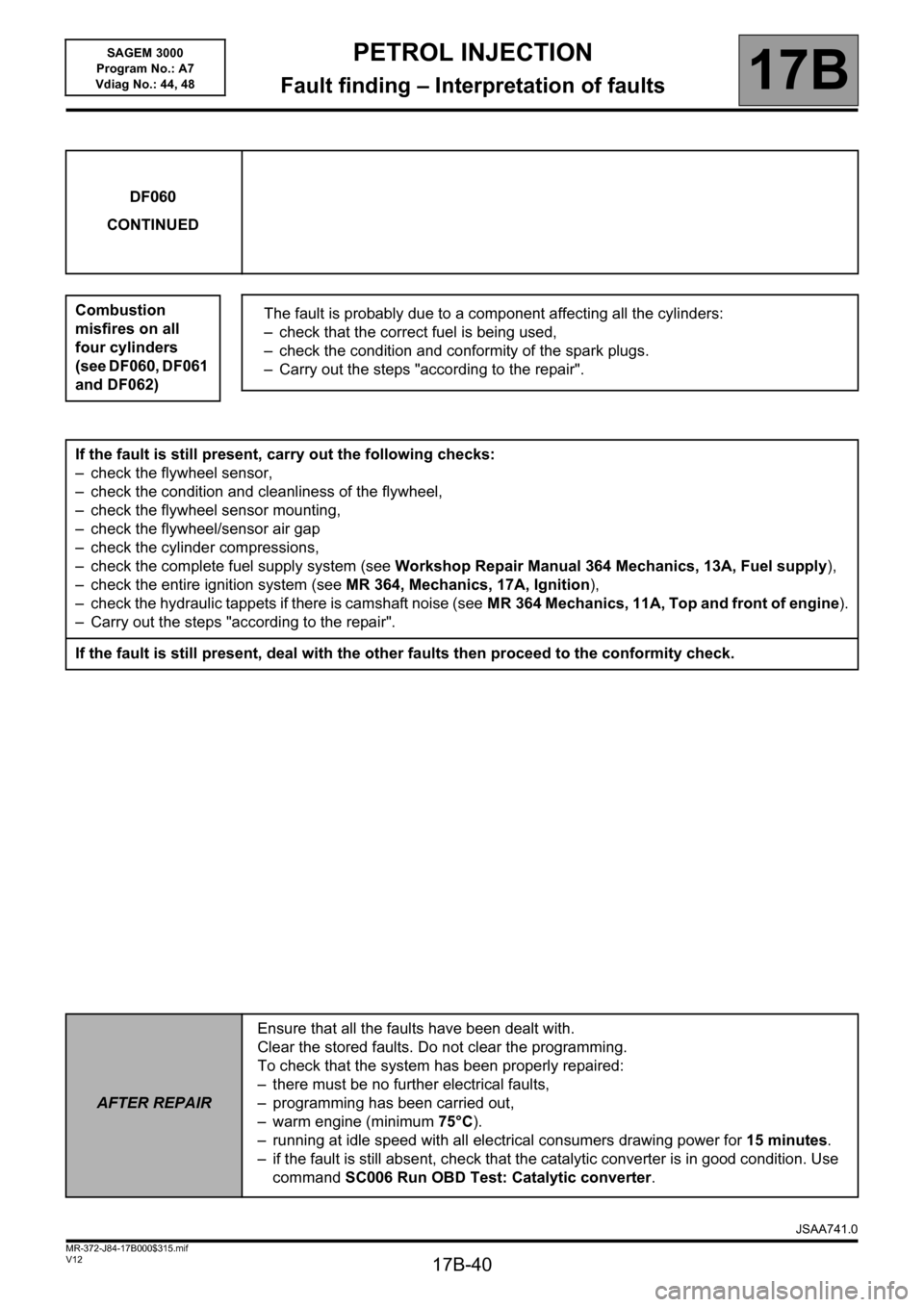
DF060
CONTINUED
Combustion
misfires on all
four cylinders
(see DF060, DF061
and DF062)
The fault is probably due to a component affecting all the cylinders:
– check that the correct fuel is being used,
– check the condition and conformity of the spark plugs.
– Carry out the steps "according to the repair".
If the fault is still present, carry out the following checks:
– check the flywheel sensor,
– check the condition and cleanliness of the flywheel,
– check the flywheel sensor mounting,
– check the flywheel/sensor air gap
– check the cylinder compressions,
– check the complete fuel supply system (see Workshop Repair Manual 364 Mechanics, 13A, Fuel supply),
– check the entire ignition system (see MR 364, Mechanics, 17A, Ignition),
– check the hydraulic tappets if there is camshaft noise (seeMR 364 Mechanics, 11A, Top and front of engine).
– Carry out the steps "according to the repair".
If the fault is still present, deal with the other faults then proceed to the conformity check.
AFTER REPAIREnsure that all the faults have been dealt with.
Clear the stored faults. Do not clear the programming.
To check that the system has been properly repaired:
– there must be no further electrical faults,
– programming has been carried out,
– warm engine (minimum 75°C).
– running at idle speed with all electrical consumers drawing power for 15 minutes.
– if the fault is still absent, check that the catalytic converter is in good condition. Use
command SC006 Run OBD Test: Catalytic converter.
JSAA741.0
Page 41 of 181
PETROL INJECTION
Fault finding – Interpretation of faults17B
17B-41V12 MR-372-J84-17B000$315.mif
SAGEM 3000
Program No.: A7
Vdiag No.: 44, 48
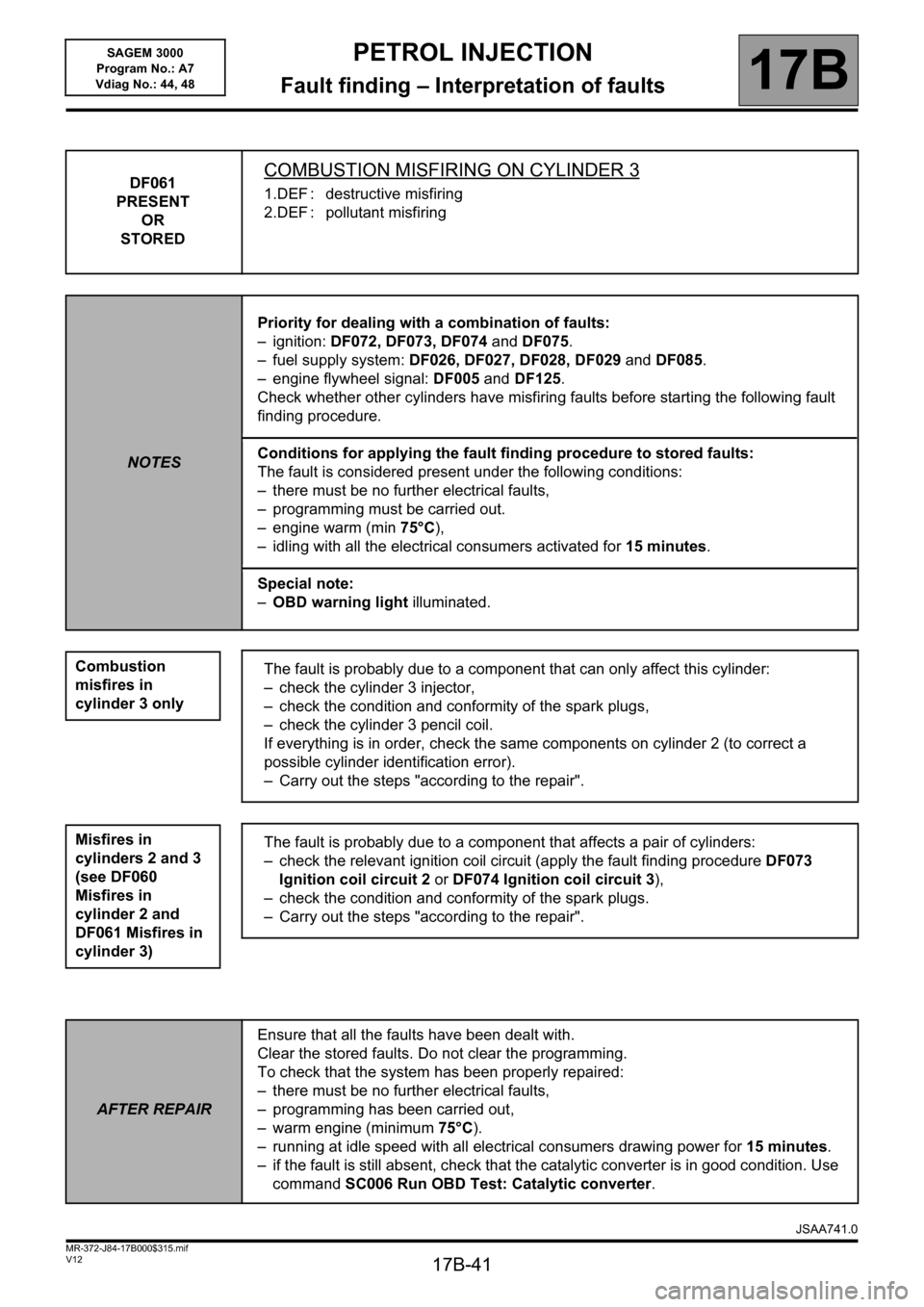
DF061
PRESENT
OR
STOREDCOMBUSTION MISFIRING ON CYLINDER 3
1.DEF : destructive misfiring
2.DEF : pollutant misfiring
NOTESPriority for dealing with a combination of faults:
– ignition: DF072, DF073, DF074 and DF075.
– fuel supply system: DF026, DF027, DF028, DF029 and DF085.
– engine flywheel signal: DF005 and DF125.
Check whether other cylinders have misfiring faults before starting the following fault
finding procedure.
Conditions for applying the fault finding procedure to stored faults:
The fault is considered present under the following conditions:
– there must be no further electrical faults,
– programming must be carried out.
– engine warm (min 75°C),
– idling with all the electrical consumers activated for 15 minutes.
Special note:
–OBD warning light illuminated.
Combustion
misfires in
cylinder 3 only
Misfires in
cylinders 2 and 3
(see DF060
Misfires in
cylinder 2 and
DF061 Misfires in
cylinder 3)
The fault is probably due to a component that can only affect this cylinder:
– check the cylinder 3 injector,
– check the condition and conformity of the spark plugs,
– check the cylinder 3 pencil coil.
If everything is in order, check the same components on cylinder 2 (to correct a
possible cylinder identification error).
– Carry out the steps "according to the repair".
The fault is probably due to a component that affects a pair of cylinders:
– check the relevant ignition coil circuit (apply the fault finding procedure DF073
Ignition coil circuit 2 or DF074 Ignition coil circuit 3),
– check the condition and conformity of the spark plugs.
– Carry out the steps "according to the repair".
AFTER REPAIREnsure that all the faults have been dealt with.
Clear the stored faults. Do not clear the programming.
To check that the system has been properly repaired:
– there must be no further electrical faults,
– programming has been carried out,
– warm engine (minimum 75°C).
– running at idle speed with all electrical consumers drawing power for 15 minutes.
– if the fault is still absent, check that the catalytic converter is in good condition. Use
command SC006 Run OBD Test: Catalytic converter.
JSAA741.0