warning light RENAULT SCENIC 2014 J95 / 3.G Petrol Injection - Sagem3000 Workshop Manual
[x] Cancel search | Manufacturer: RENAULT, Model Year: 2014, Model line: SCENIC, Model: RENAULT SCENIC 2014 J95 / 3.GPages: 181
Page 2 of 181

PETROL INJECTION
Fault finding – Introduction17B
17B-2V12 MR-372-J84-17B000$045.mif
117B
SAGEM 3000
Program No.: A7
Vdiag No.: 44, 48PETROL INJECTION
Fault finding – Introduction
1. SCOPE OF THIS DOCUMENT
This document presents the fault finding method applicable to all computers with the following specifications:
2. PREREQUISITES FOR FAULT FINDING
Documentation type
Fault finding procedures (this document):
– Assisted fault finding (integrated into the diagnostic tool), Dialogys.
Wiring Diagrams:
– Visu-Schéma (CD-ROM), paper.
Type of diagnostic tools
–CLIP
Special tooling required
3. REMINDERS
Procedure
To run fault finding on the vehicle's computers, switch on the ignition in fault finding mode (forced + after ignition
feed).
Proceed as follows:
– with the vehicle card in the card reader,
– press and hold Start button (longer than 5 seconds) with start-up conditions not fulfilled,
– connect the diagnostic tool and perform the required operations.
To cut off the + after ignition feed, proceed as follows:
– disconnect the diagnostic tool,
– press the Start button twice briefly (less than 3 seconds),
– Check that the + after ignition feed has been cut off by checking that the computer warning lights on the instrument
panel have gone out. Vehicle(s): Mégane II / Mégane Sport / Scénic II
Function concerned: Petrol injectionName of computer: Sagem S3000
Program no.: A7
Vdiag No.: 44, 48
Special tooling required
Multimeter
Elé. 1497Bornier
Elé. 1681Universal bornier
Note:
The left-hand and right-hand xenon bulb computers are powered when the dipped headlights are lit.
Fault finding procedures can only be carried out on them after the ignition has been switched on in fault finding
mode (+ after ignition imposed) and the dipped headlights are on.
S3000_V44_PRELI/S3000_V48_PRELI
MR-372-J84-17B000$045.mif
Page 9 of 181

PETROL INJECTION
Fault finding – System operation17B
17B - 9V12 MR-372-J84-17B000$090.mif
SAGEM 3000
Program No.: A7
Vdiag No.: 44, 48
2. OPERATIONAL SAFETY
Warning lights illumination
The S3000 injection system manages the illumination of three warning lights and the issuing of warning messages
according to the severity of the faults detected, to inform the customer and to direct fault finding.
The injection computer manages the illumination of warning lights and warning messages displayed on the instrument
panel. These warning lights illuminate during the starting phase and in the event of an injection fault or engine
overheating.
The warning light illumination signals reach the instrument panel via the multiplex network.
Warning light illumination principle
During the starting phase (START button pressed) the OBD (On Board Diagnostic) warning light comes on for
approximately 3 seconds then goes out.
If there is an injection fault (severity 1), the INJECTION FAULT written message lights up followed by the SERVICE
warning light. It indicates a reduced level of operation and a limited safety level.
The driver should carry out repairs as soon as possible.
Components involved:
– motorised throttle valve,
– accelerator pedal potentiometer,
– inlet manifold pressure sensor,
–computer,
– actuator feed,
– computer feed.
If there is a serious injection fault (severity 2), the red engine symbol and the word STOP appear (display with
information display only), with the ENGINE OVERHEATING written message followed by the STOP warning light
and a buzzer. If this happens, the vehicle must be stopped immediately.
When a fault causing excessive pollution in the exhaust fumes is detected, the orange OBD warning light, an engine
symbol, will be lit:
–flashing in the event of a fault which might irreparably damaged the catalytic converter (destructive misfire). If this
happens you must stop the vehicle immediately,
–constantly in the case of non-compliance with the anti-pollution standards (pollutant misfire, catalytic converter
fault, oxygen sensor faults, inconsistency between the oxygen sensors and canister fault).
Mileage travelled with fault
This parameter serves to measure the distance travelled with one of the injection fault warning lights on: level 1 fault
warning light (amber), coolant temperature overheating warning light, or OBD warning light.
The counter can be reset to 0 using the diagnostic tool.
JSAA741.0
Page 17 of 181

PETROL INJECTION
Fault finding – Fault summary table17B
17B - 17V12 MR-372-J84-17B000$270.mif
SAGEM 3000
Program No.: A7
Vdiag No.: 44, 48PETROL INJECTION
Fault finding – Fault summary table
Tool
faultsHexadecimal
DTC codesDescriptionLevel 1 fault
warning lightNo warning
light onOBD warning
light
DF0010115Coolant temperature
sensor circuit1.DEF
DF0020110Air temperature sensor
circuit1.DEF
DF0040235Turbocharging pressure
sensor circuit1.DEF/2.DEF 1.DEF/2.DEF
DF0080225Pedal potentiometer
circuit gang 1CO.0/CC.1
1.DEF
DF0092120Pedal potentiometer
circuit gang 2CO.0/CC.1
DF0110641 Sensor feed voltage no. 1 1.DEF/2.DEF
DF0120651 Sensor feed voltage no. 2 1.DEF/2.DEF
DF0260201Cylinder 1 injector control
circuitCO/ CC.0
CC.1
DF0270202Cylinder 2 injector control
circuitCO/ CC.0
CC.1
DF0280203Cylinder 3 injector control
circuitCO/ CC.0
CC.1
DF0290204Cylinder 4 injector control
circuitCO/ CC.0
CC.1
DF0370633 Engine immobiliser 1.DEF
DF0380606 Computer 1.DEF
DF0460560 Battery voltage 1.DEF
DF0490530 Refrigerant sensor circuit 1.DEF
DF0540243Turbocharging solenoid
valve control circuitCO/ CC.0
CC.1
JSAA741.0
MR-372-J84-17B000$270.mif
Page 18 of 181

PETROL INJECTION
Fault finding – Fault summary table17B
17B - 18V12 MR-372-J84-17B000$270.mif
SAGEM 3000
Program No.: A7
Vdiag No.: 44, 48
Tool
faultsHexadecimal
DTC codesDescriptionLevel 1 fault
warning lightNo warning
light onOBD warning
light
DF0590301 Misfiring on cylinder 1 1.DEF/2.DEF
DF0600302 Misfiring on cylinder 2 1.DEF/2.DEF
DF0610303 Misfiring on cylinder 3 1.DEF/2.DEF
DF0620304 Misfiring on cylinder 4 1.DEF/2.DEF
DF0650300 Combustion misfire 1.DEF/2.DEF
DF0720351Cylinder 1 ignition coil
circuitCO.0/CC.1
DF0730352Cylinder 2 ignition coil
circuitCO.0/CC.1
DF0740353Cylinder 3 ignition coil
circuitCO.0/CC.1
DF0750354Cylinder 4 ignition coil
circuitCO.0/CC.1
DF0782101Motorised throttle
control circuitCC.1/1.DEF
DF0790638Motorised throttle valve
automatic control6.DEF1.DEF/2.DEF
3.DEF/4.DEF
5.DEF
DF0800010Camshaft dephaser
circuit
DF0810443Canister bleed solenoid
valve circuitCO/ CC.0
CC.1
DF0820135Upstream oxygen
sensor heating circuitCO.0/CC.1
DF0830141Downstream oxygen
sensor heating circuitCO.0/CC.1
JSAA741.0
Page 19 of 181

PETROL INJECTION
Fault finding – Fault summary table17B
17B - 19V12 MR-372-J84-17B000$270.mif
SAGEM 3000
Program No.: A7
Vdiag No.: 44, 48
*AT: Automatic Transmission
*BVR: Sequential gearboxTool
faultsHexadecimal
DTC codesDescriptionLevel 1 fault
warning lightNo warning
light onOBD warning
light
DF0840685Actuator relay control
circuit1.DEF
DF0850627Fuel pump relay control
circuitCO/ CC.0
CC.1
DF0862600Coolant pump control
circuitCO/ CO.0
CC.1
DF0880325 Pinking sensor circuit 1.DEF
DF0890105Inlet manifold pressure
sensor circuit1.DEF
2.DEF
DF0910500 Vehicle speed signal 1.DEF
DF0920130Upstream oxygen
sensor circuitCO.0
CC.1
1.DEF
DF0930136Downstream oxygen
sensor circuitCO.0/CC.1
DF0950120Throttle potentiometer
circuit gang 1CO.0/CC.1
1.DEF
DF0960220Throttle potentiometer
circuit gang 2CO.1/CC.0
DF099C101TA* or BVR*
connection via the
multiplex network1.DEF
DF100C155Instrument panel
multiplex connection1.DEF
DF101C122Multiplex ESP
connection1.DEF
DF1050585Cruise control/speed
limiter on/off circuit1.DEF
DF1060575Cruise Control/Speed
Limiter function selector
on steering wheel1.DEF
DF108C115LPG/CNG computer
multiplex connection1.DEF
JSAA741.0
Page 20 of 181

PETROL INJECTION
Fault finding – Fault summary table17B
17B - 20V12 MR-372-J84-17B000$270.mif
SAGEM 3000
Program No.: A7
Vdiag No.: 44, 48
Tool
faultsHexadecimal
DTC codesDescriptionLevel 1 fault
warning lightNo warning
light onOBD warning
light
DF1090313 Low fuel level misfire 1.DEF/2.DEF
DF1100420 Catalytic converter 1.DEF
DF1190340 Camshaft sensor signal
DF1250314Torque sensor
programming1.DEF
DF1261604Passenger
compartment heating
resistor (RCH)1.DEF
DF1270703Brake switch no. 1
circuit1.DEF
DF1280571 Brake switch 2 circuit 1.DEF
DF1540335Flywheel signal sensor
circuit1.DEF/2.DEF
DF3980170Fuel circuit operating
fault1.DEF
DF4550460 Low fuel level signal 1.DEF
DF6080830 Clutch pedal switch 1.DEF
DF6121605Oil vapour anti-icing
resistor circuitCO.0
DF6351301LPG cylinder 1
combustion misfire1.DEF/2.DEF
DF6361302LPG cylinder 2
combustion misfire1.DEF/2.DEF
DF6371303LPG cylinder 3
combustion misfire1.DEF/2.DEF
DF6381304LPG cylinder 4
combustion misfire1.DEF/2.DEF
DF6391300Combustion misfire in
LPG mode1.DEF/2.DEF/
3.DEF
JSAA741.0
Page 21 of 181

PETROL INJECTION
Fault finding – Interpretation of faults17B
17B-21V12 MR-372-J84-17B000$315.mif
SAGEM 3000
Program No.: A7
Vdiag No.: 44, 48PETROL INJECTION
Fault finding – Interpretation of faults
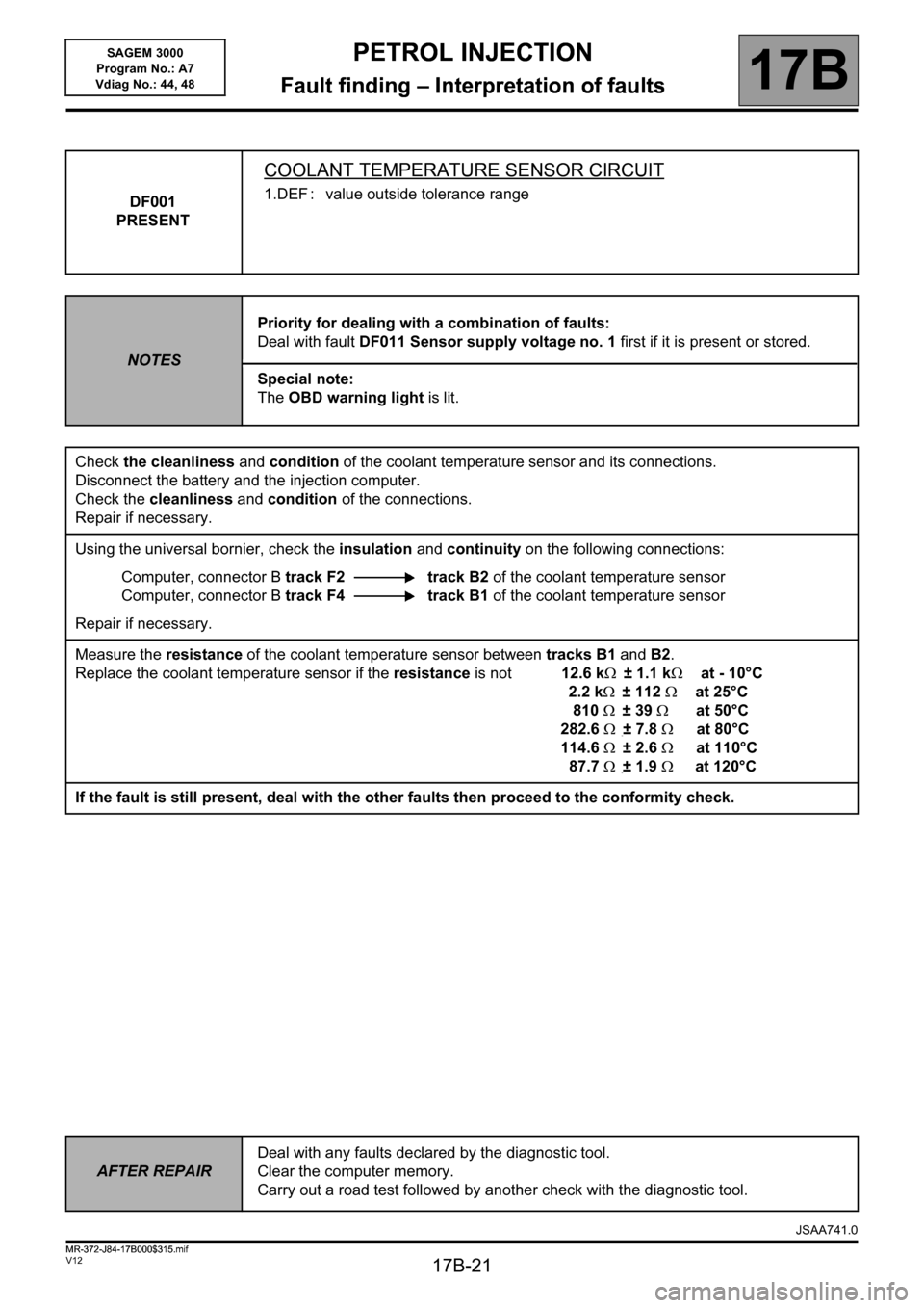
DF001
PRESENT
COOLANT TEMPERATURE SENSOR CIRCUIT
1.DEF : value outside tolerance range
NOTESPriority for dealing with a combination of faults:
Deal with fault DF011 Sensor supply voltage no. 1 first if it is present or stored.
Special note:
The OBD warning light is lit.
Check the cleanliness and condition of the coolant temperature sensor and its connections.
Disconnect the battery and the injection computer.
Check the cleanliness and condition of the connections.
Repair if necessary.
Using the universal bornier, check the insulation and continuity on the following connections:
Computer, connector B track F2 track B2 of the coolant temperature sensor
Computer, connector B track F4 track B1 of the coolant temperature sensor
Repair if necessary.
Measure the resistance of the coolant temperature sensor between tracks B1 and B2.
Replace the coolant temperature sensor if the resistance is not 12.6 k± 1.1 kat - 10°C
2.2 k±112at 25°C
810±39at 50°C
282.6±7.8at 80°C
114.6±2.6at 110°C
87.7±1.9at 120°C
If the fault is still present, deal with the other faults then proceed to the conformity check.
AFTER REPAIRDeal with any faults declared by the diagnostic tool.
Clear the computer memory.
Carry out a road test followed by another check with the diagnostic tool.
JSAA741.0
MR-372-J84-17B000$315.mif
Page 22 of 181

PETROL INJECTION
Fault finding – Interpretation of faults17B
17B-22V12 MR-372-J84-17B000$315.mif
SAGEM 3000
Program No.: A7
Vdiag No.: 44, 48
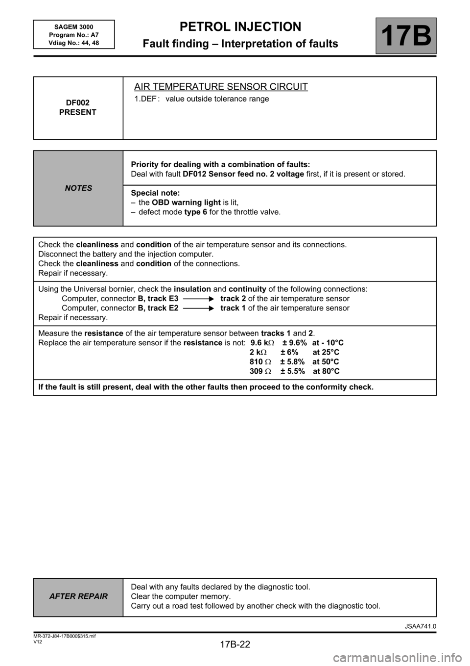
DF002
PRESENT
AIR TEMPERATURE SENSOR CIRCUIT
1.DEF : value outside tolerance range
NOTESPriority for dealing with a combination of faults:
Deal with fault DF012 Sensor feed no. 2 voltage first, if it is present or stored.
Special note:
– the OBD warning light is lit,
– defect mode type 6 for the throttle valve.
Check the cleanliness and condition of the air temperature sensor and its connections.
Disconnect the battery and the injection computer.
Check the cleanliness and condition of the connections.
Repair if necessary.
Using the Universal bornier, check the insulation and continuity of the following connections:
Computer, connectorB, track E3 track 2 of the air temperature sensor
Computer, connectorB, track E2 track 1 of the air temperature sensor
Repair if necessary.
Measure the resistance of the air temperature sensor between tracks 1 and 2.
Replace the air temperature sensor if the resistance is not:9.6 k± 9.6% at - 10°C
2k±6% at 25°C
810±5.8% at 50°C
309±5.5% at 80°C
If the fault is still present, deal with the other faults then proceed to the conformity check.
AFTER REPAIRDeal with any faults declared by the diagnostic tool.
Clear the computer memory.
Carry out a road test followed by another check with the diagnostic tool.
JSAA741.0
Page 23 of 181

PETROL INJECTION
Fault finding – Interpretation of faults17B
17B-23V12 MR-372-J84-17B000$315.mif
SAGEM 3000
Program No.: A7
Vdiag No.: 44, 48
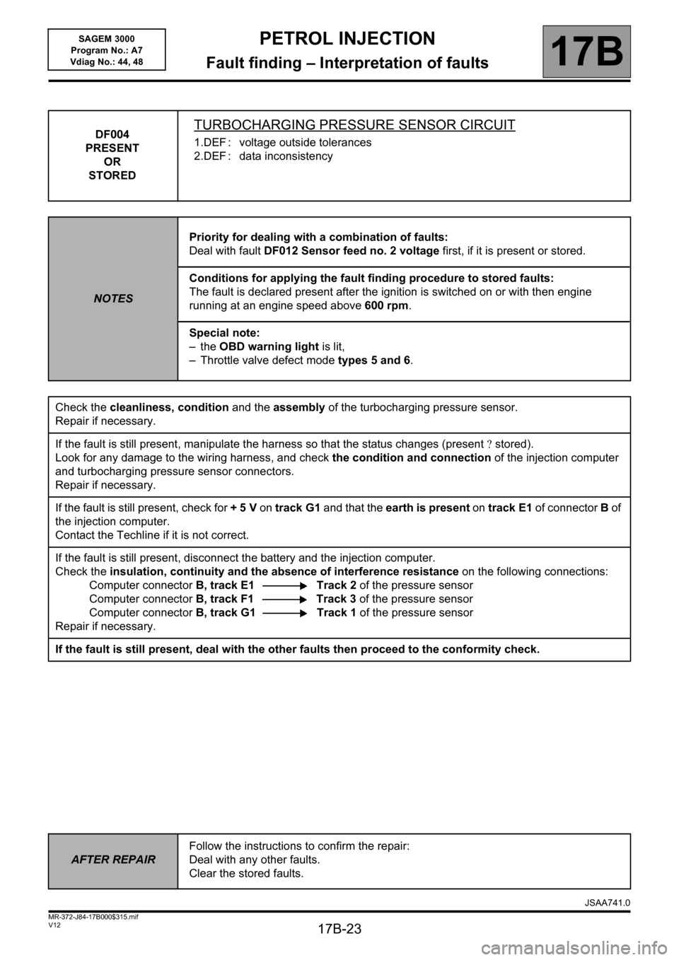
DF004
PRESENT
OR
STOREDTURBOCHARGING PRESSURE SENSOR CIRCUIT
1.DEF : voltage outside tolerances
2.DEF : data inconsistency
NOTESPriority for dealing with a combination of faults:
Deal with fault DF012 Sensor feed no. 2 voltage first, if it is present or stored.
Conditions for applying the fault finding procedure to stored faults:
The fault is declared present after the ignition is switched on or with then engine
running at an engine speed above 600 rpm.
Special note:
– the OBD warning light is lit,
– Throttle valve defect mode types 5 and 6.
Check the cleanliness, condition and the assembly of the turbocharging pressure sensor.
Repair if necessary.
If the fault is still present, manipulate the harness so that the status changes (present stored).
Look for any damage to the wiring harness, and check the condition and connection of the injection computer
and turbocharging pressure sensor connectors.
Repair if necessary.
If the fault is still present, check for + 5 V on track G1 and that the earth is present on track E1 of connector B of
the injection computer.
Contact the Techline if it is not correct.
If the fault is still present, disconnect the battery and the injection computer.
Check the insulation, continuity and the absence of interference resistance on the following connections:
Computer connectorB, track E1 Track 2 of the pressure sensor
Computer connectorB, track F1 Track 3 of the pressure sensor
Computer connectorB, track G1 Track 1 of the pressure sensor
Repair if necessary.
If the fault is still present, deal with the other faults then proceed to the conformity check.
AFTER REPAIRFollow the instructions to confirm the repair:
Deal with any other faults.
Clear the stored faults.
JSAA741.0
Page 24 of 181

PETROL INJECTION
Fault finding – Interpretation of faults17B
17B-24V12 MR-372-J84-17B000$315.mif
SAGEM 3000
Program No.: A7
Vdiag No.: 44, 48
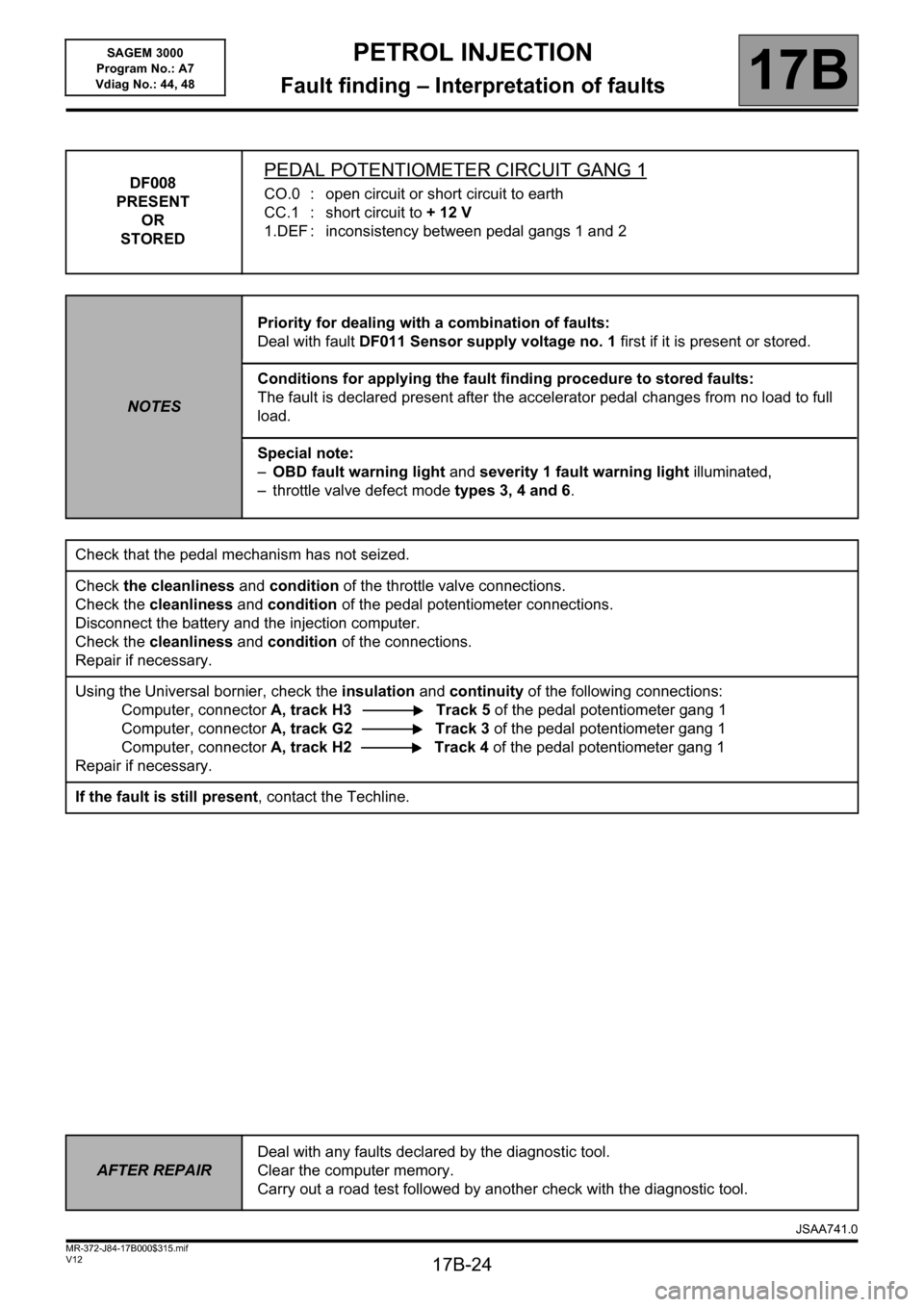
DF008
PRESENT
OR
STOREDPEDAL POTENTIOMETER CIRCUIT GANG 1
CO.0 : open circuit or short circuit to earth
CC.1 : short circuit to + 12 V
1.DEF : inconsistency between pedal gangs 1 and 2
NOTESPriority for dealing with a combination of faults:
Deal with fault DF011 Sensor supply voltage no. 1 first if it is present or stored.
Conditions for applying the fault finding procedure to stored faults:
The fault is declared present after the accelerator pedal changes from no load to full
load.
Special note:
–OBD fault warning light and severity 1 fault warning light illuminated,
– throttle valve defect mode types 3, 4 and 6.
Check that the pedal mechanism has not seized.
Check the cleanliness and condition of the throttle valve connections.
Check the cleanliness and condition of the pedal potentiometer connections.
Disconnect the battery and the injection computer.
Check the cleanliness and condition of the connections.
Repair if necessary.
Using the Universal bornier, check the insulation and continuity of the following connections:
Computer, connectorA, track H3 Track 5 of the pedal potentiometer gang 1
Computer, connectorA, track G2 Track 3 of the pedal potentiometer gang 1
Computer, connectorA, track H2 Track 4 of the pedal potentiometer gang 1
Repair if necessary.
If the fault is still present, contact the Techline.
AFTER REPAIRDeal with any faults declared by the diagnostic tool.
Clear the computer memory.
Carry out a road test followed by another check with the diagnostic tool.
JSAA741.0