ECU RENAULT SCENIC 2015 J95 / 3.G User Guide
[x] Cancel search | Manufacturer: RENAULT, Model Year: 2015, Model line: SCENIC, Model: RENAULT SCENIC 2015 J95 / 3.GPages: 270, PDF Size: 6.08 MB
Page 208 of 270

5.8
TYRE INFLATION KIT (5/5)
Precautions when using the kit
The kit should not be operated for more
than 15 consecutive minutes.
Nothing should be placed
around the driver’s feet
as such objects may slide
under the pedals during
sudden braking manoeuvres and
obstruct their use.
Please be aware that a
poorly tightened or miss-
ing valve cap can make the
tyres less airtight and lead
to pressure loss.
Always use valve caps identical to
those fitted originally and tighten
them fully.
Following repair with the kit,
do not travel further than
120 miles (200 km). In addi-
tion, reduce your speed and
under no circumstances exceed
48 mph (80 km/h). The sticker,
which you must affix in a prominent
position on the dashboard, reminds
you of this.
Depending on the country or local
legislation, a tyre repaired with the
inflation kit may need to be replaced.
10
If a minimum pressure of 1.8 bar is
not reached after 15 minutes, repair
is not possible; do not drive the ve-
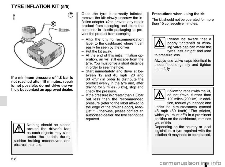
hicle but contact an approved dealer. Once the tyre is correctly inflated,
remove the kit: slowly unscrew the in-
flation adapter
10 to prevent any repair
product from escaping and store the
container in plastic packaging to pre-
vent the product from escaping.
– Affix the driving recommendation label to the dashboard where it can
easily be seen by the driver;
– Put the kit away.
– At the end of this initial inflation op- eration, air will still escape from the
tyre. You must drive a short distance
in order to seal the hole.
– Start immediately and drive at be- tween 12 and 40 mph (20 and
60 km/h) in order to distribute the
product evenly in the tyre and, after
driving for 2 miles (3 km), stop and
check the pressure.
– If the pressure is greater than 1.3 bar but less than the recommended
pressure (refer to the label affixed to
the edge of the driver’s door), read-
just it. Otherwise, please contact an
authorised dealer: the tyre cannot be
repaired.
F
Page 209 of 270

5.9
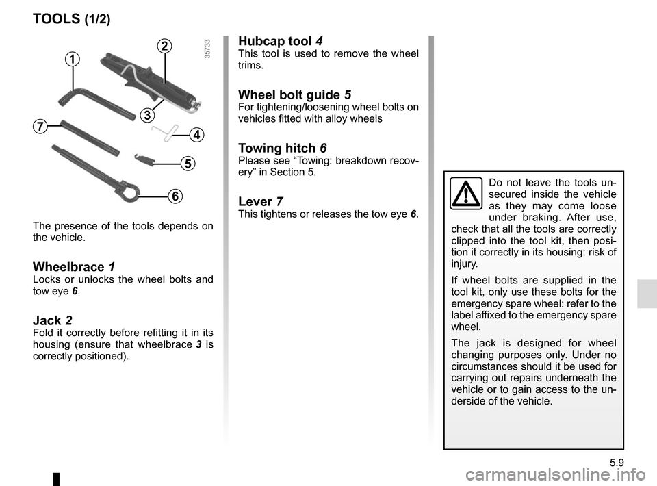
Hubcap tool 4This tool is used to remove the wheel
trims.
Wheel bolt guide 5For tightening/loosening wheel bolts on
vehicles fitted with alloy wheels
Towing hitch 6Please see “Towing: breakdown recov-
ery” in Section 5.
Lever 7This tightens or releases the tow eye 6.
The presence of the tools depends on
the vehicle.
Wheelbrace 1Locks or unlocks the wheel bolts and
tow eye 6.
Jack 2Fold it correctly before refitting it in its
housing (ensure that wheelbrace 3 is
correctly positioned).
TOOLS (1/2)
Do not leave the tools un-
secured inside the vehicle
as they may come loose
under braking. After use,
check that all the tools are correctly
clipped into the tool kit, then posi-
tion it correctly in its housing: risk of
injury.
If wheel bolts are supplied in the
tool kit, only use these bolts for the
emergency spare wheel: refer to the
label affixed to the emergency spare
wheel.
The jack is designed for wheel
changing purposes only. Under no
circumstances should it be used for
carrying out repairs underneath the
vehicle or to gain access to the un-
derside of the vehicle.
2
1
4
6
5
73
Page 210 of 270

5.10
TOOLS (2/2)/WHEEL TRIM
12
A
BC
D
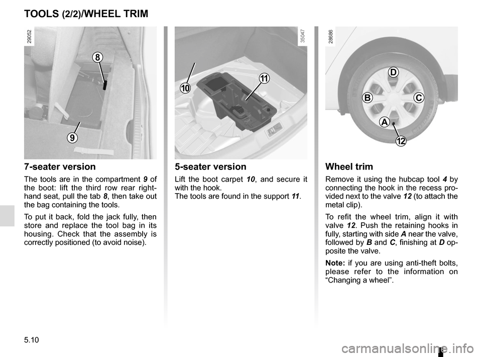
Wheel trim
Remove it using the hubcap tool 4 by
connecting the hook in the recess pro-
vided next to the valve 12 (to attach the
metal clip).
To refit the wheel trim, align it with
valve 12. Push the retaining hooks in
fully, starting with side A near the valve,
followed by B and C, finishing at D op-
posite the valve.
Note: if you are using anti-theft bolts,
please refer to the information on
“Changing a wheel”.
5-seater version
Lift the boot carpet 10, and secure it
with the hook.
The tools are found in the support 11.
7-seater version
The tools are in the compartment 9 of
the boot: lift the third row rear right-
hand seat, pull the tab 8, then take out
the bag containing the tools.
To put it back, fold the jack fully, then
store and replace the tool bag in its
housing. Check that the assembly is
correctly positioned (to avoid noise).
9
8
10
11