air condition RENAULT TWINGO 2009 2.G Chasiss ABS Owner's Guide
[x] Cancel search | Manufacturer: RENAULT, Model Year: 2009, Model line: TWINGO, Model: RENAULT TWINGO 2009 2.GPages: 76
Page 49 of 76
38C-49
MR-413-X44-38C000$517_eng.mif
V1
ANTI-LOCK BRAKING SYSTEM
Fault finding - Interpretation of faults
MK70 ABS
Vdiag No: 04
38C
DF250
DF251
DF252
DF253
DF254
PRESENT
OR
STOREDENGINE SPEED MULTIPLEX SIGNAL
AVERAGE EFFECTIVE TORQUE MULTIPLEX SIGNAL
TORQUE REQUEST MULTIPLEX FEEDBACK SIGNAL
CALCULATED TORQUE MULTIPLEX SIGNAL
RESISTING TORQUE MULTIPLEX SIGNAL
NOTESSpecial notes:
Although it is stored in the computer, the ABS system is not faulty.
Perform fault finding on the injection system using the diagnostic tool.
Note:
The injection computer does not always store these transient faults as quickly as the
ABS computer.
If no fault is stored in the injection computer, start the engine; if there is no fault
present, contact the Techline. After solving the injection system problem, erase
the faults from the ABS computer memory.
Conditions for applying the fault finding procedure to stored faults:
The fault is declared present when the engine is started up.
Carry out fault finding on the injection system (see MR413 Fault Finding, 13B, Diesel injection or 17B,
Petrol injection).
If the fault is still present, contact the Techline.
AFTER REPAIRClear the computer fault memory.
Carry out a road test followed by another check with the diagnostic tool.
ABS_V04_DF250 / ABS_V04_DF251
ABS_V04_DF252 / ABS_V04_DF253 / ABS_V04_DF254
Page 50 of 76
38C-50
MR-413-X44-38C000$517_eng.mif
V1
ANTI-LOCK BRAKING SYSTEM
Fault finding - Interpretation of faults
MK70 ABS
Vdiag No: 04
38C
DF311
PRESENT
OR
STOREDNO BVR MULTIPLEX SIGNAL
NOTESSpecial notes:
Even though it is stored in the computer, this fault does not cause the warning lights to
come on or a fault message, because the ABS system is not faulty.
Perform fault finding on the BVR (sequential gearbox) using the diagnostic tool.
Note:
After repairing the fault in the BVR (sequential gearbox), clear the fault memory
in the ABS system.
Priority in the event of a number of faults:
Deal with fault DF152 Multiplex network first if it is present or stored.
Conditions for applying the fault finding procedure to stored faults:
The fault is declared present when the engine is started up.
Check the gearbox type configuration with the diagnostic tool, using command LC008 Gearbox type.
If the configuration is not correct, configure the gearbox type present on the vehicle using configuration command
CF079 Gearbox type.
Check the BVR (sequential gearbox) using the diagnostic tool.
Run a multiplex network test (see 88B, Multiplex).
If the fault is still present, contact the Techline.
AFTER REPAIRClear the computer fault memory.
Carry out a road test followed by another check with the diagnostic tool.
ABS_V04_DF311
Page 53 of 76
38C-53
MR-413-X44-38C000$658_eng.mif
V1
38C
ANTI-LOCK BRAKING SYSTEM
Fault finding - Interpretation of statuses
ET017
BRAKE PEDAL
NOTESSpecial notes:
Only carry out the checks if the PRESSED and RELEASED statuses are inconsistent
with the pedal position.
Use the Technical Note wiring diagram for New Twingo.
STATUS
"RELEASED"
Brake pedal
depressed
If brake lights operate:
–Check the continuity of connection 65A between components 160 and 1094.
If the connector is faulty (see NT6015, Repairing electrical wiring, wiring: Precaution
for repairs), repair the connector, otherwise replace the wiring.
If the brake lights are not working:
–Check the condition, mounting and adjustment of the brake light switch and the
conformity of the bulbs.
–Remove the brake light switch and check that it is operating correctly:
Connection continuity Connection insulation
Switch pressed
(Brake pedal released)AP10 and 5A AP10 and 65A
Switch released
(Brake pedal depressed)AP10 and 65A AP10 and 5A
–Replace the switch if necessary.
Intermediate connector R107 and component 160 and 1081 disconnected:
–Check the continuity and insulation of connection AP10 between
component 1016 and intermediate connector R107.
–Check the continuity and insulation of connection AP10 between
component 160 and intermediate connector R107.
If the connector is faulty (see NT6015, Repairing electrical wiring, wiring:
Precaution for repairs), repair the connector or the wiring, otherwise replace the
wiring.
AFTER REPAIRClear the computer fault memory.
Carry out a road test followed by another check with the diagnostic tool.
ABS_V04_ET017
MK70 ABS
Vdiag No: 04
MR-413-X44-38C000$658_eng.mif
Page 54 of 76
38C-54
MR-413-X44-38C000$658_eng.mif
V1
MK70 ABS
Vdiag No: 04ANTI-LOCK BRAKING SYSTEM
Fault finding - Interpretation of statuses38C
ET017
CONTINUED 1
Connectors of components 645, 172, 173, 639 and 1094, intermediate connectors
R107 and R15 and connector of component 119 (if present on the vehicle)
disconnected from connection 65A:
–Check the insulation of connection 65A between component 160 and
intermediate connector R107.
–Check the insulation of connection 65A between component 172 and
intermediate connector R107.
–Check the insulation of connection 65A between component 173 and
intermediate connector R107.
–Check the insulation of connection 65A between intermediate connectors R107
and R15.
–Check the insulation of connection 65A between component 639 and
intermediate connector R15.
–Check the insulation of connection 65A between component 645 and
intermediate connector R107.
If the connector is faulty (see NT6015, Repairing electrical wiring, wiring:
Precaution for repairs), repair the connector, otherwise replace the wiring.
–Check for + 12 V after ignition feed on connection AP10 of component 1016 to
earth MAH.
If the checks reveal no faults, carry out a check of each component associated with
connection 65A and AP10 (short circuits).
Check the condition and positioning of the F5 5A fuse (see MR411 Mechanical
systems, 81C, Fuses: 16A).
–Check the condition, mounting and adjustment of the brake light switch and the
conformity of the bulbs.
–Remove the brake light switch and check that it is operating correctly:
Connection continuity Connection insulation
Switch pressed
(Brake pedal released)AP10 and 5A AP10 and 65A
Switch released
(Brake pedal
depressed)AP10 and 65A AP10 and 5A
–Replace the switch if necessary.
Connectors of components 645, 172, 173, 639 and 1094, intermediate
connectors R107 and R15 and connector of component 119 (if present on the vehicle)
disconnected from connection 65A
–Check the insulation of connection 65A between component 160 and
intermediate connector R107.
STATUS
DEPRESSED:
Brake pedal
released
AFTER REPAIRClear the computer fault memory.
Carry out a road test followed by another check with the diagnostic tool.
Page 57 of 76
38C-57
MR-413-X44-38C000$752_eng.mif
V1
38C
ANTI-LOCK BRAKING SYSTEM
Fault finding - Dealing with command modes
CLEARING
RZ001: Fault memory.
This command is used for clearing the computer's stored faults.
SPECIAL COMMANDS
SC001: Check target teeth.
This command tests the condition of the teeth on each wheel.
Select command SC001 "Check target teeth" and follow the instructions.
The test result should indicate 48 sprockets.
AFTER REPAIRClear the computer fault memory.
Carry out a road test followed by another check with the diagnostic tool.
MK70 ABS
Vdiag No: 04
MR-413-X44-38C000$752_eng.mif
Page 59 of 76
38C-59
MR-413-X44-38C000$846_eng.mif
V1
38C
ANTI-LOCK BRAKING SYSTEM
Fault finding - Dealing with command modes
AC003
AC004
AC005
AC006FRONT LEFT-HAND WHEEL SOLENOID VALVES
FRONT RIGHT-HAND WHEEL SOLENOID VALVES
REAR LEFT-HAND WHEEL SOLENOID VALVES
REAR RIGHT-HAND WHEEL SOLENOID VALVES
NOTESConditions of use of the command.
Ignition on, engine stopped and vehicle speed zero.
Before using the commands, check that the battery is fully charged.
The previous 4 commands allow the hydraulic check of each wheel.
Raise the vehicle in order to be able to rotate the wheels, and check that they rotate freely.
Keep the brake pedal depressed to prevent the wheel being tested from being turned by hand (do not brake so
firmly that full braking power is reached).
Select and confirm the command of the wheel being examined (e.g. Front left-hand wheel solenoid valves, etc.)
Turn the wheel concerned by hand; 5 locking/unlocking cycles should be noted on the wheel.
AFTER REPAIRClear the computer fault memory.
Carry out a road test followed by another check with the diagnostic tool.
ABS_V04_AC003 / ABS_V04_AC004
ABS_V04_AC005 / ABS_V04_AC006
MK70 ABS
Vdiag No: 04
MR-413-X44-38C000$846_eng.mif
Page 60 of 76
38C-60
MR-413-X44-38C000$846_eng.mif
V1
ANTI-LOCK BRAKING SYSTEM
Fault finding - Dealing with command modes
MK70 ABS
Vdiag No: 04
38C
AC016
PUMP MOTOR TEST
NOTESConditions of use of the command.
Ignition on, engine stopped and vehicle speed zero.
Before using the command, check that the battery is fully charged.
This command is used to test the pump motor control circuit.
Select command AC016 Pump Motor Test.
The motor must run for 5 seconds.
AFTER REPAIRClear the computer fault memory.
Carry out a road test followed by another check with the diagnostic tool.
ABS_V04_AC016
Page 61 of 76
38C-61
MR-413-X44-38C000$846_eng.mif
V1
ANTI-LOCK BRAKING SYSTEM
Fault finding - Dealing with command modes
MK70 ABS
Vdiag No: 04
38C
AC153
AC154
AC155
AC156BLEED FRONT LEFT-HAND WHEEL
BLEED FRONT RIGHT-HAND WHEEL
BLEED REAR LEFT-HAND WHEEL
BLEED REAR RIGHT-HAND WHEEL
NOTESConditions of use of the command.
Ignition on, engine stopped and vehicle speed zero.
Before using the commands, check that the battery is fully charged.
These 4 commands should only be used if you observe lengthening of the brake pedal travel during a road test
with ABS regulation (the system should have been bled in advance using the conventional procedure).
See ALP8.
AFTER REPAIRClear the computer fault memory.
Carry out a road test followed by another check with the diagnostic tool.
ABS_V04_AC153 / ABS_V04_AC154
ABS_V04_AC155 / ABS_V04_AC156
Page 62 of 76
38C-62
MR-413-X44-38C000$846_eng.mif
V1
ANTI-LOCK BRAKING SYSTEM
Fault finding - Dealing with command modes
MK70 ABS
Vdiag No: 04
38C
AC195
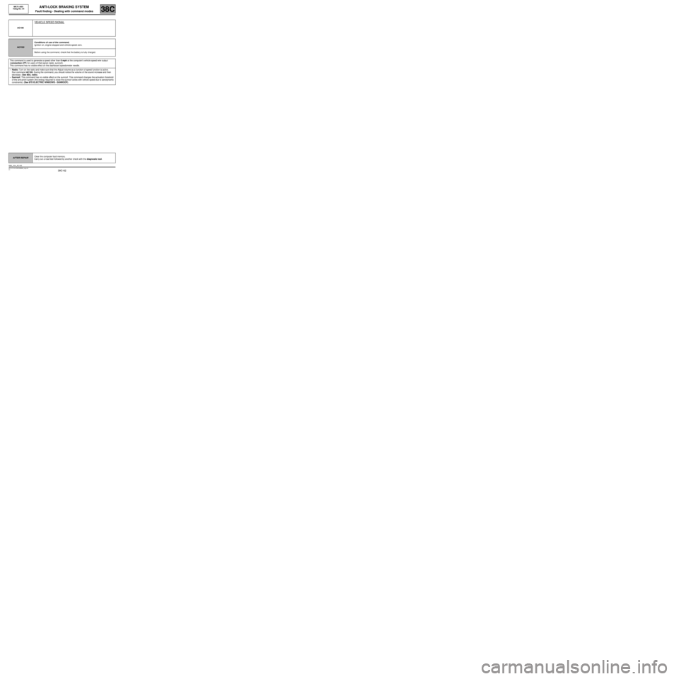
VEHICLE SPEED SIGNAL
NOTESConditions of use of the command.
Ignition on, engine stopped and vehicle speed zero.
Before using the command, check that the battery is fully charged.
This command is used to generate a speed other than 0 mph at the computer's vehicle speed wire output
(connection 47F) for users of that signal (radio, sunroof).
This command has no visible effect on the dashboard speedometer needle.
–Radio: Turn on the radio and make sure that the Adjust volume as a function of speed function is active.
Run command AC195. During the command, you should notice the volume of the sound increase and then
decrease. (See 86A, radio).
–Sunroof: This command has no visible effect on the sunroof. This command changes the activation threshold
of the anti-pinch system (the energy required to close the sunroof varies with vehicle speed due to aerodynamic
constraints). (See 87D ELECTRIC WINDOWS - SUNROOF).
AFTER REPAIRClear the computer fault memory.
Carry out a road test followed by another check with the diagnostic tool.
ABS_V04_AC195
Page 63 of 76
38C-63
MR-413-X44-38C000$846_eng.mif
V1
ANTI-LOCK BRAKING SYSTEM
Fault finding - Dealing with command modes
MK70 ABS
Vdiag No: 04
38C
AC196
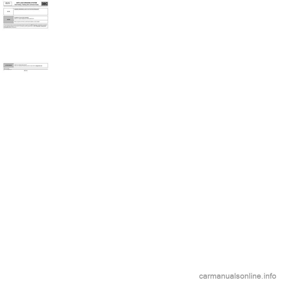
HAZARD WARNING LIGHT ACTIVATION REQUEST
NOTESConditions of use of the command.
Ignition on, engine stopped and vehicle speed zero.
Before using the command, check that the battery is fully charged.
This command sends a hazard warning light activation request to the UCH (Passenger compartment connection
unit) to test their operation in the event of emergency braking (depending on UCH, Passenger Compartment
Connection Unit configuration).
AFTER REPAIRClear the computer fault memory.
Carry out a road test followed by another check with the diagnostic tool.
ABS_V04_AC196