diagram RENAULT TWINGO 2009 2.G Chasiss - Power Assisted Steering Workshop Manual
[x] Cancel search | Manufacturer: RENAULT, Model Year: 2009, Model line: TWINGO, Model: RENAULT TWINGO 2009 2.GPages: 54
Page 2 of 54
36B-2
MR-413-X44-36B000$067.mif
V2
36B
POWER – ASSISTED STEERING
Fault finding – Introduction
1. SCOPE OF THIS DOCUMENT
This document presents the fault finding procedure applicable to all computers with the following specifications:
2. PREREQUISITES FOR FAULT FINDING
Documentation type
Fault finding procedures (this manual):
–Assisted fault finding (integrated into the diagnostic tool), Dialogys.
Wiring Diagrams:
–Visu-Schéma (CD-ROM), paper.
Type of diagnostic tools
–CLIP + multiplex line sensor
Special tooling required
3. REMINDERS
Procedure
To run diagnostics on the vehicle computers, proceed as follows:
–turn the ignition key to APC,
–connect the diagnostic tool and perform the required operations.
To cut off + after ignition feed, proceed as follows:
–disconnect the diagnostic tool,
–turn the ignition key to OFF,
–switch off the ignition. Vehicle(s): New Twingo
Function concerned: Electric power steeringComputer name: EPAS
Vdiag No.: 04 - 08
Special tooling required
Multimeter
Elé. 1681 Universal bornier
DAE_V04_PRELI/DAE_V08_PRELI
EPAS
Vdiag No.: 04 - 08
MR-413-X44-36B000$067.mif
Page 18 of 54
36B-18
MR-413-X44-36B000$469.mif
V2
POWER – ASSISTED STEERING
Fault finding – Interpretation of faults
EPAS
Vdiag No.: 04 - 08
36B
DF017
PRESENT
OR
STOREDMOTOR CIRCUIT
DEF : Short circuit to earth or short circuit to 12 V
CC.O : Short circuit to earth
CO : Open circuit
NOTESConditions for applying the fault finding procedure to stored faults:
The fault is declared present after the engine was started and after turning the
steering wheel from lock to lock, then returning it to the centre.
Notes:
This fault causes:
Sudden loss of steering assistance with illumination of the Fault warning light +
STOP + Beep.
Use the Wiring Diagram Technical Note for New Twingo.
With + after ignition feed off, check the connection and condition (possible wiring damage) of the connector of
component 502 and its clips.
If the connector is faulty (see Technical Note 6015A, Electrical wiring repair, Wiring: Precautions for repair),
repair the connector, otherwise replace the steering column.
Connector of component 502 and component 540 disconnected: check the insulation against +, -, and between
the connections and check the continuity of the following connections:
●Connection 109R
●Connection 109S
If the connection or connections are faulty (see Technical Note 6015A, Electrical wiring repair, Wiring:
Precautions for repair), repair the connectors or the wiring, otherwise replace the steering column.
If the fault is still present, contact the Techline.
AFTER REPAIRDeal with any other faults.
Clear the stored faults.
Check that the EPAS is working.
DAE_V04_DF017 /DAE_V08_DF017
Page 19 of 54
36B-19
MR-413-X44-36B000$469.mif
V2
POWER – ASSISTED STEERING
Fault finding – Interpretation of faults
EPAS
Vdiag No.: 04 - 08
36B
DF023
STORED
+ AFTER IGNITION FEED
CO.O: Open circuit or short circuit to earth
NOTESConditions for applying the fault finding procedure to stored faults:
The fault is stored after the after ignition feed is switched off at speeds over 6 mph
(10 km/h).
Notes:
This fault causes:
Sudden loss of steering assistance with illumination of the Fault warning light +
STOP + Beep.
Use the Wiring Diagram Technical Note for New Twingo.
Important note: this fault may indicate the system is being incorrectly used by the customer (ignition cut off at
speeds over 6 mph (10 km/h)).
In this instance, this fault should be ignored.
With + after ignition feed off, check the connection and condition (possible wiring damage) of the connector
of component 502 and its clips.
If the connector is faulty (see Technical Note 6015A, Repairing electrical wiring, Wiring: Precautions for
repair), repair the connector, otherwise replace the wiring.
With the connector of component 1016 disconnected, check the insulation and continuity of connection AP23
between components 502 and 1016.
If the connection or connections are faulty (see Technical Note 6015A, Repairing electrical wiring, Wiring:
Precautions for repair), repair the wiring, otherwise replace it.
If the checks reveal no faults, perform a conformity check of component 1016.
If the fault is still present, contact the Techline.
AFTER REPAIRDeal with any other faults.
Clear the stored faults.
Check that the EPAS is working.
DAE_V04_DF023M/ DAE_V08_DF023M
Page 20 of 54
36B-20
MR-413-X44-36B000$469.mif
V2
POWER – ASSISTED STEERING
Fault finding – Interpretation of faults
EPAS
Vdiag No.: 04 - 08
36B
DF028
PRESENT
OR
STOREDENGINE SPEED ABSENT
DEF: Open circuit, short circuit to earth or short circuit to + 12 V
NOTESConditions for applying the fault finding procedure to stored faults:
The fault is declared present after having started the engine and turned the steering
wheel from lock to lock, then returning it to the centre.
Notes:
This fault causes:
No assistance with illumination of the Fault warning light + STOP + Beep.
Use the Wiring Diagram Technical Note for New Twingo.
Start the vehicle and use the diagnostic tool to check the conformity of PR004 Engine speed (not zero).
If necessary, carry out a fault finding procedure on the injection system.
With + after ignition feed off, check the connection and condition (possible wiring damage) of the connector of
component 502 and its clips.
If the connector is faulty (see Technical Note 6015A, Repairing electrical wiring, Wiring: Precautions for
repair), repair the connector, otherwise replace the wiring.
With the connector of component 502 and intermediate connector R107 disconnected: check the insulation and
the continuity of connection H7 between component 502 and intermediate connector R107.
Connector of components 119 and 120 disconnected: check the insulation and the continuity of connection H7
between component 120 and intermediate connector R107.
If the connection or connections are faulty (see Technical Note 6015A, Electrical wiring repair, Wiring:
Precautions for repair), repair the wiring, otherwise replace the wiring.
If the fault is still present, contact the Techline.
AFTER REPAIRDeal with any other faults.
Clear the stored faults.
Check that the EPAS is working.
DAE_V04_DF028 /DAE_V08_DF028
Page 21 of 54
36B-21
MR-413-X44-36B000$469.mif
V2
POWER – ASSISTED STEERING
Fault finding – Interpretation of faults
EPAS
Vdiag No.: 04 - 08
36B
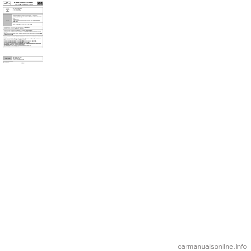
DF037
PRESENT
OR
STOREDBATTERY VOLTAGE
1. DEF: Under voltage
2. DEF: Excess voltage
NOTESConditions for applying the fault finding procedure to stored faults:
The fault is declared present after starting the engine and turning the steering wheel
from lock to lock left to right.
Notes:
This fault causes:
Sudden loss of steering assistance with illumination of the Fault warning light +
STOP + Beep.
Use the Wiring Diagram Technical Note for New Twingo.
Check the tightness and condition of the battery terminals (see 80A, Battery).
Check the charging circuit (see 16A, Starting - Charging).
Check the condition and position of the 80 A fuse in the engine fuse and relay box.
Check the condition and position of fuse F3 (15 A) fuse in the passenger compartment fuse box (see 81C,
Fuse box).
With the ignition on and the engine stopped, check for a voltage equal to the battery voltage on connections BP81
and AP23 against earth ML.
With the connectors of component 502 disconnected, check the condition and conformity of the connectors and
their clips.
If the connector is faulty (see Technical Note 6015A, Repairing electrical wiring, Wiring: Precautions for
repair), repair the connector, otherwise replace the wiring.
With the connectors of components 597 and 1016 disconnected:
Check the continuity and insulation of connection BP81 between components 502 and 597.
Check the continuity and insulation of connection AP23 between components 502 and 1016.
Check the continuity and insulation of connection ML of component 502.
If the connection or connections are faulty (see Technical Note 6015A, Repairing electrical wiring, Wiring:
Precautions for repair), repair the wiring, otherwise replace it.
If the checks reveal no faults, check the conformity of components 597 and 1016.
If the fault is still present, contact the Techline.
AFTER REPAIRDeal with any other faults.
Clear the stored faults.
Check that the EPAS is working.
DAE_V04_DF037/DAE_V08_DF037
Page 22 of 54
36B-22
MR-413-X44-36B000$469.mif
V2
POWER – ASSISTED STEERING
Fault finding – Interpretation of faults36B
EPAS
Vdiag No.: 04
DF038
PRESENT
OR
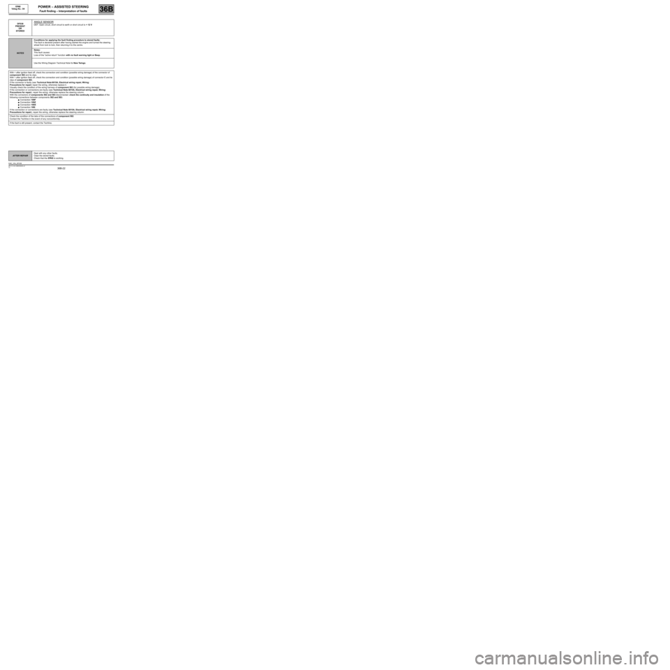
STOREDANGLE SENSOR
DEF: Open circuit, short circuit to earth or short circuit to + 12 V
NOTESConditions for applying the fault finding procedure to stored faults:
The fault is declared present after having started the engine and turned the steering
wheel from lock to lock, then returning it to the centre.
Notes:
This fault causes:
Loss of the "active return" function with no fault warning light or Beep.
Use the Wiring Diagram Technical Note for New Twingo.
With + after ignition feed off, check the connection and condition (possible wiring damage) of the connector of
component 502 and its clips.
With + after ignition feed off, check the connection and condition (possible wiring damage) of connector E and its
clips of component 583.
If the connector is faulty (see Technical Note 6015A, Electrical wiring repair, Wiring:
Precautions for repair) repair the wiring, otherwise replace it.
Visually check the condition of the wiring harness of component 583 (for possible wiring damage).
If the connection or connections are faulty (see Technical Note 6015A, Electrical wiring repair, Wiring:
Precautions for repair), repair the wiring, otherwise replace the steering column.
With the connectors of components 502 and 583 disconnected: check the continuity and insulation of the
following connections between components 502 and 583:
●Connection 109F
●Connection 109Z
●Connection 109X
●Connection 109I
If the connection or connections are faulty (see Technical Note 6015A, Electrical wiring repair, Wiring:
Precautions for repair), repair the wiring, otherwise replace the steering column.
Check the condition of the tabs of the connections of component 502.
Contact the Techline in the event of any nonconformity.
If the fault is still present, contact the Techline.
AFTER REPAIRDeal with any other faults.
Clear the stored faults.
Check that the EPAS is working.
DAE_V04_DF038
Page 23 of 54
36B-23
MR-413-X44-36B000$469.mif
V2
POWER – ASSISTED STEERING
Fault finding – Interpretation of faults
EPAS
Vdiag No.: 04 - 08
36B
DF039
DF048
DF050
DF054
PRESENT
OR
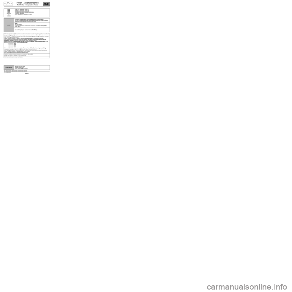
STOREDTORQUE SENSOR CIRCUIT
TORQUE SENSOR CIRCUIT
TORQUE SENSOR CIRCUIT SIGNAL 2
TORQUE SENSOR
CO.O: Open circuit or short circuit to earth
NOTESConditions for applying the fault finding procedure to stored faults:
The fault is declared present after having started the engine and turned the steering
wheel from lock to lock, then returning it to the centre.
Notes:
This fault causes:
Sudden loss of steering assistance with illumination of the Fault warning light +
STOP + Beep.
Use the Wiring Diagram Technical Note for New Twingo.
With + after ignition feed off, check the connection and condition (possible wiring damage) of connector C and
its clips of component 502.
If the connector is faulty (see Technical Note 6015A, Electrical wiring repair, Wiring: Precautions for repair)
repair the wiring, otherwise replace it.
Visually check the condition of the wiring harness of component 850 (for possible wiring damage).
If the connection or connections are faulty (see Technical Note 6015A, Electrical wiring repair, Wiring:
Precautions for repair), repair the wiring, otherwise replace the steering column.
With the connectors of components 502 and 850 disconnected, check the continuity and insulation of the
following connections between components 502 and 850.
●Connection 109K
●Connection 109M
●Connection 109N
●Connection 109P
If the connection or connections are faulty (see Technical Note 6015A, Electrical wiring repair, Wiring:
Precautions for repair), repair the wiring, otherwise replace the steering column.
With + after ignition feed off, disconnect and check the condition and conformity of connector C and its clips.
Visually check the condition of the torque sensor wiring harness.
In the event of a nonconformity, replace the steering column.
Check the condition of the connection pins of components 502 and 850.
Contact the Techline in the event of any nonconformity.
If the fault is still present, contact the Techline.
AFTER REPAIRDeal with any other faults.
Clear the stored faults.
Check that the EPAS is working.
DAE_V04_DF039/DAE_V08_DF039/DAE_V04_DF048/DAE_V08_DF048
DAE_V04_DF050/DAE_V08_DF050/DAE_V04_DF054/DAE_V08_DF054
Page 24 of 54
36B-24
MR-413-X44-36B000$469.mif
V2
POWER – ASSISTED STEERING
Fault finding – Interpretation of faults
EPAS
Vdiag No.: 04 - 08
36B
DF043
PRESENT
OR
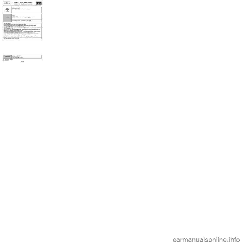
STOREDVEHICLE SPEED
DEF: Open circuit, short circuit to earth or to + 12 V
NOTESNotes:
This fault causes:
Assistance in defect mode with no fault warning light or Beep
(Insufficient assistance).
Use the Wiring Diagram Technical Note for New Twingo.
Carry out a road test.
Check the consistency of the speed signal on the instrument panel.
If necessary, carry out fault finding on the ABS/ESP system (see 38C, Anti-lock braking system).
Then use the diagnostic tool to check that PR003 is not zero.
With + after ignition feed off, check the connection and condition (possible wiring damage) of the connector of
component 502 and its clips.
If the connector is faulty (see Technical Note 6015A, Repairing electrical wiring, Wiring: Precautions for
repair), repair the connector, otherwise replace the wiring.
With the intermediate connector R107 and the connector of component 502 disconnected, check the continuity
and insulation of connection 47F between component 502 and intermediate connector R107.
With the connector of components 1579, 261 and 1094 disconnected: check the continuity and insulation of
connection 47F between component 1094 and intermediate connector R107.
If the connection or connections are faulty (see Technical Note 6015A, Electrical wiring repair, Wiring:
Precautions for repair), repair the wiring, otherwise replace the wiring.
If the checks reveal no faults, check the conformity of components 1579, 261 and 1094.
If the fault is still present, contact the Techline.
AFTER REPAIRDeal with any other faults.
Clear the stored faults.
Check that the EPAS is working.
DAE_V04_DF043/DAE_V08_DF043
Page 43 of 54
36B-43
MR-413-X44-36B000$938.mif
V2
36B
POWER – ASSISTED STEERING
Fault finding – Fault finding Chart
ALP 1 No dialogue with the computer
NOTESUse the Technical Note wiring diagram for New Twingo.
Try to establish dialogue with a computer on another vehicle to check that the diagnostic tool is not faulty.
If the tool is not faulty and no dialogue is established with any other computer of the same vehicle, check the
tightness and condition of the battery terminals (see 80A, Battery).
Check the charging circuit (see 16A, Starting - Charging).
With connector A of component 502 and the connector of components 1222 and 1094 disconnected, check the
continuity and insulation of connection HK between components 502 and 225.
If the connection(s) are faulty and there is a repair method (see Technical Note 6015A, Repairing electrical
wiring, W iring: Precautions for repair), repair the wiring, otherwise replace it.
If the checks reveal no faults, check the conformity of components 1022 and 1094.
Check the condition and the position of the 80 A fuse in the engine fuse and relay box.
Check the condition and the position of fuse F3 (15 A) in the passenger compartment fuse box.
With the ignition on and the engine stopped, check for a voltage equal to the battery voltage on connections BP81
and AP23 against earth ML.
Connectors of component 502 disconnected, check the condition and conformity of the connectors and clips.
If the connector is faulty (see Technical Note 6015A, Repairing electrical wiring, Wiring: Precautions for
repair), repair the connector, otherwise replace the wiring.
With the connectors of components 597 and 1016 disconnected:
Check the continuity and insulation of connection BP81 between components 502 and 597.
Check the continuity and insulation of connection AP23 between components 502 and 1016.
Check the continuity and insulation of connection ML of component 502.
If the connection(s) are faulty and there is a repair method (see Technical Note 6015A, Repairing electrical
wiring, W iring: Precautions for repair), repair the wiring, otherwise replace it.
If the checks reveal no faults, check the conformity of components 597 and 1016.
If the fault is still present, contact Techline.
AFTER REPAIRPerform a test using the diagnostic tool.
DAE_V04_ALP1/ DAE_V08_ALP1
EPAS
Vdiag No.: 04 - 08
MR-413-X44-36B000$938.mif
Page 45 of 54
36B-45
MR-413-X44-36B000$938.mif
V2
POWER – ASSISTED STEERING
Fault finding – Fault finding Chart
EPAS
Vdiag No.: 04 - 08
36B
ALP 3 SUDDEN LOSS OF ASSISTANCE
NOTESOnly consult this customer complaint after a complete check with the
diagnostic tool.
Use the Technical Note wiring diagram for New Twingo.
Connectors of component 502 disconnected, check the condition and conformity of the connectors and clips.
If the connector is faulty (see Technical Note 6015A, Repairing electrical wiring, Wiring: Precautions for
repair), repair the connector, otherwise replace the wiring.
With the connector of component 597 disconnected:
Check the continuity and insulation of connection BP81 between components 502 and 597.
Check the continuity and insulation of connection ML of component 502.
If the connection or connections are faulty (see Technical Note 6015A, Repairing electrical wiring, Wiring:
Precautions for repair), repair the wiring, otherwise replace it.
If the checks reveal no faults, perform a conformity check of component 597.
Check the pressure and condition of the tyres, the steering, joints and the front axle geometry.
If the fault is still present, contact Techline.
AFTER REPAIRPerform a check using the diagnostic tool.
DAE_V04_ALP3/ DAE_V08_ALP3