engine RENAULT TWINGO 2009 2.G Chasiss User Guide
[x] Cancel search | Manufacturer: RENAULT, Model Year: 2009, Model line: TWINGO, Model: RENAULT TWINGO 2009 2.GPages: 281
Page 196 of 281
37A-17
MECHANICAL COMPONENT CONTROLS
Brake servo: Removal - Refitting
JB1 or JH1 or JH3 or JR5, and LEFT-HAND DRIVE
37A
aCheck that the brake servo seal (5) is in place and
replace the seal if it is faulty.
aBefore refitting, check the dimension L = 153.3 mm.
aIf the dimension is not correct, replace the brake ser-
vo.
II - REFITTING OPERATION FOR PART
CONCERNED
aRefit:
-the brake servo,
-the brake servo nuts (3) .aTorque tighten the brake servo nuts (25 Nm).
aRefit the new connecting shaft (3) between the
brake pedal and the brake servo rod from right to left
and from top to bottom.
III - FINAL OPERATION.
aRefit:
-the non-return valve on the brake servo,
-the master cylinder (see 37A, Mechanical compo-
nent controls, Master cylinder: Removal - Refit-
ting, page 37A-1) ,
-the injection computer mounting,
-the engine wiring bracket.
aRefit the petrol injection computer (see Petrol injec-
tion computer: Removal - Refitting) (17B, Petrol
injection).
aRefit the diesel injection computer (see Diesel in-
jection computer: Removal - Refitting) (13B, Die-
sel injection).
109206
91101-1
109205
D4F or D7F or K4M
K9K
Page 198 of 281
37A-19
MECHANICAL COMPONENT CONTROLS
Brake servo: Removal - Refitting
RIGHT-HAND DRIVE
37A
REMOVAL
I - REMOVAL PREPARATION OPERATION
aPosition the vehicle on a two-post lift (see Vehicle:
Towing and lifting) (02A, Lifting equipment).
aRemove:
-the front right-hand wheel (see 35A, Wheels and
tyres, Wheel: Removal - Refitting, page 35A-1) ,
-the front right-hand wheel arch liner (see Front
wheel arch liner: Removal - Refitting) (55A, Ex-
terior protection),
-the scuttle panel grille (see Scuttle panel grille:
Removal - Refitting) (56A, Exterior equipment),
-the scoop under the scuttle panel grille (see Scoop
under the scuttle panel grille: Removal - Refit-
ting) (56A, Exterior equipment).aRemove:
-the fuel vapour recirculation solenoid valve pipes
(1) ,
-the fuel vapour recirculation solenoid valve con-
nector (2) ,
-the fuel vapour recirculation solenoid valve (3) ,
-the fuel vapour recirculation solenoid valve support
bolt (4) ,
-the fuel vapour recirculation solenoid valve support
(5) ,
-the brake master cylinder (see 37A, Mechanical
component controls, Master cylinder: Removal
- Refitting, page 37A-1) ,
-the brake servo non-return valve (see 37A, Me-
chanical component controls, Brake servo non-
return valve: Removal - Refitting, page 37A-11) .
aRemove the ignition coil (see Coils: Removal - Re-
fitting) (17A, Ignition). Special tooling required
Mot. 1672Low er engine support.
Equipment required
refrigerant charging station
Tightening torquesm
“brake - clutch pedal”
assembly nuts21 Nm
brake servo nuts21 Nm
123852
D4F or D7F
Page 199 of 281
37A-20
MECHANICAL COMPONENT CONTROLS
Brake servo: Removal - Refitting
RIGHT-HAND DRIVE
37A
aDrain the refrigerant circuit using a refrigerant
charging station (see Refrigerant circuit: Drain-
ing - Filling) (62A, Air conditioning).
aRemove the "dehydrator reservoir - expansion
valve" connecting pipe (see Dehydrator reservoir -
expansion valve connecting pipe: Removal - Re-
fitting) (62A, Air conditioning).
aRemove:
-the air filter (see Air filter: Removal - Refitting)
(12A, Fuel mixture),
-the bolts (6) of the air filter unit heat-resistant pro-
tector,
-the air filter unit heat-resistant protector (7) .
aRemove:
-the rear suspended engine mounting (see Lower
engine tie-bar: Removal - Refitting) (19D, En-
gine mounting),-the right-hand suspended engine mounting (see
Right-hand suspended engine mounting: Re-
moval - Refitting) (19D, Engine mounting).
aRemove the catalytic converter (see Catalytic con-
verter: Removal - Refitting) (19B, Exhaust).
aRemove the exhaust manifold (see Exhaust mani-
fold: Removal - Refitting) (12A, Fuel mixture). AIR CONDITIONING or CLIMATE CONTROL
D7F
123868
D4F
D4F, and 780
K4M
Page 201 of 281
37A-22
MECHANICAL COMPONENT CONTROLS
Brake servo: Removal - Refitting
RIGHT-HAND DRIVE
37A
aFully lower the engine using the (Mot. 1672).
aPivot the brake servo so that the servo pushrod (15)
is oriented upwards.
aRemove the brake servo by moving the engine for-
ward as far as possible.
aRemove the brake servo from underneath the vehi-
cle.
aRemove the brake servo.
REFITTING
I - REFITTING PREPARATION OPERATION
aCheck that the brake servo seal (16) is in place and
replace the seal if it is faulty.
aThe dual safety connecting shaft between the brake
servo pushrod and the brake pedal must be re-
placed every time it is removed.
aCheck the following dimension before refitting: (X1)
= 132.6 mm. D4F
123847
D4F
K4M
109206
91101
Page 202 of 281
37A-23
MECHANICAL COMPONENT CONTROLS
Brake servo: Removal - Refitting
RIGHT-HAND DRIVE
37A
II - REFITTING OPERATION FOR PART
CONCERNED
aPosition the brake servo by moving the engine for-
ward as far as possible and tilting the pushrod up-
wards.
aRefit the brake servo from underneath the vehicle.
aRefit the brake servo.
aPosition the “brake - clutch pedal” assembly on the
bulkhead.
aTorque tighten the “brake - clutch pedal” assem-
bly nuts (21 Nm).
aRefit:
-the new dual safety connecting shaft between the
brake servo pushrod and the brake pedal from right
to left and from top to bottom,
-the brake servo nuts.
aTorque tighten the brake servo nuts (21 Nm).
III - FINAL OPERATION.
aRefit:
-the clutch master cylinder support,
-the clutch master cylinder support bolts,
-the clutch master cylinder rod on the clutch pedal.
aRefit the exhaust manifold (see Exhaust manifold:
Removal - Refitting) (12A, Fuel mixture).aRefit the catalytic converter (see Catalytic convert-
er: Removal - Refitting) (19B, Exhaust).
aRefit:
-the right-hand suspended engine mounting (see
Right-hand suspended engine mounting: Re-
moval - Refitting) (19D, Engine mounting),
-the rear suspended engine mounting (see Lower
engine tie-bar: Removal - Refitting) (19D, En-
gine mounting).
aRefit:
-the air filter box heat-resistant protector,
-the air filter box heat-resistant protector bolts,
-the air filter (see Air filter: Removal - Refitting)
(12A, Fuel mixture).
aRefit the "dehydrator reservoir - expansion valve"
connection (see Dehydrator reservoir - expansion
valve connecting pipe: Removal - Refitting) (62A,
Air conditioning).
aFill the refrigerant circuit using a refrigerant charg-
ing station (see Refrigerant circuit: Draining -
Filling) (62A, Air conditioning).
aRefit the ignition coil (see Coils: Removal - Refit-
ting) (17A, Ignition). D4F
K4M
JH3 or JR5
K4M
D4F, and 780
D4F
D7F
AIR CONDITIONING or CLIMATE CONTROL
D4F or D7F
Page 204 of 281
37A-25
MECHANICAL COMPONENT CONTROLS
Vacuum pump: Removal - Refitting
K9K
37A
REMOVAL
I - REMOVAL PREPARATION OPERATION
aRemove:
-the engine cover,
-the air filter unit (see Air filter unit: Removal - Re-
fitting) (MR 411, 12A, Fuel mixture).
II - OPERATION FOR REMOVAL OF PART
CONCERNED
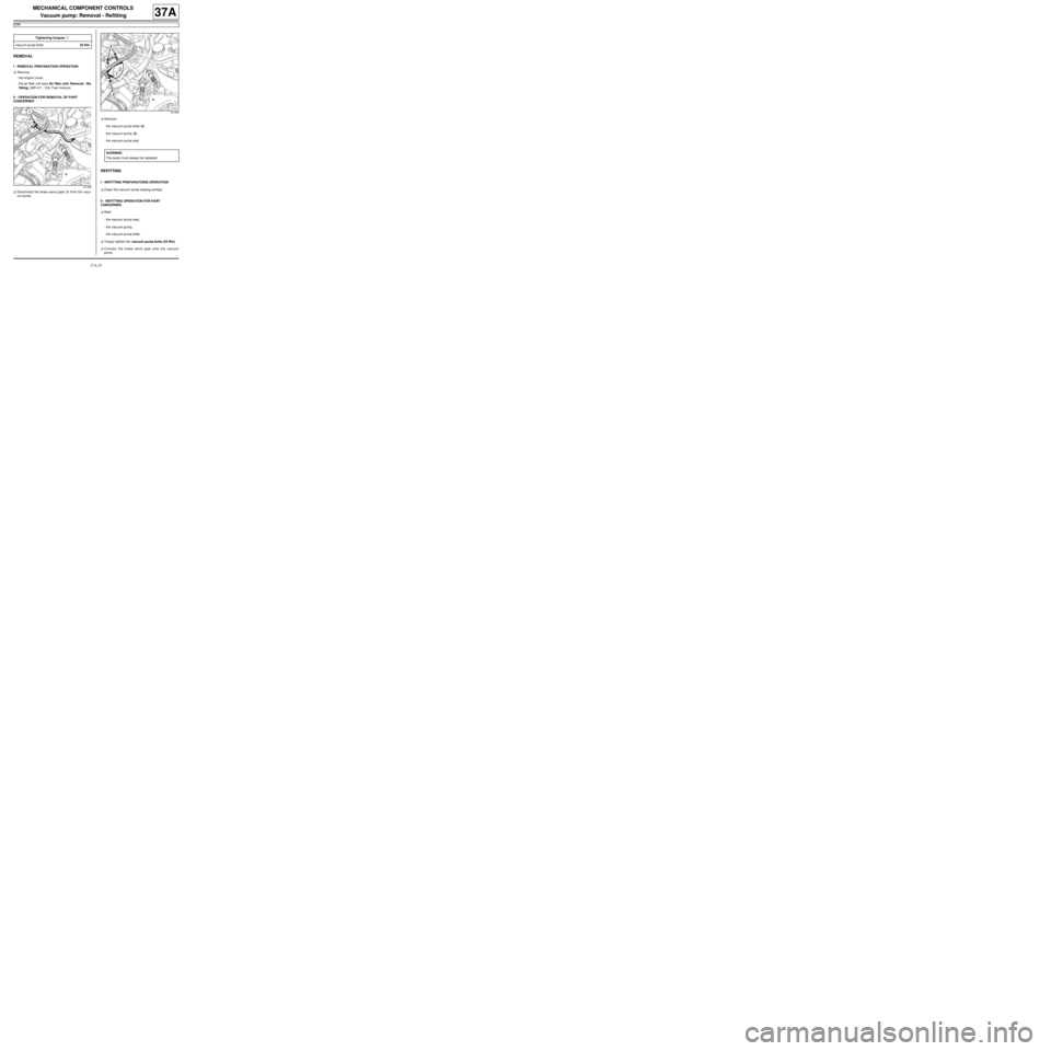
aDisconnect the brake servo pipe (1) from the vacu-
um pump.aRemove:
-the vacuum pump bolts (2) ,
-the vacuum pump (3) ,
-the vacuum pump seal.
REFITTING
I - REFITTING PREPARATIONS OPERATION
aClean the vacuum pump sealing surface.
II - REFITTING OPERATION FOR PART
CONCERNED
aRefit:
-the vacuum pump seal,
-the vacuum pump,
-the vacuum pump bolts.
aTorque tighten the vacuum pump bolts (25 Nm).
aConnect the brake servo pipe onto the vacuum
pump. Tightening torquesm
vacuum pump bolts25 Nm
121356
121355
WARNING
The seals m ust always be replaced.
Page 205 of 281
37A-26
MECHANICAL COMPONENT CONTROLS
Vacuum pump: Removal - Refitting
K9K
37A
III - FINAL OPERATION.
aRefit:
-the air filter unit (see Air filter unit: Removal - Re-
fitting) (MR 411, 12A, Fuel mixture),
-the engine cover.
Page 233 of 281
37A-54
MECHANICAL COMPONENT CONTROLS
Clutch circuit: Bleed
JH3 or JR5
37A
Bleed in the event of:
-dead travel,
-pedal at mid-travel,
-pedal to the floor,
-poor gear changing.
I - PRECAUTIONS DURING REPAIR
Risks relating to contamination.
aThe hydraulic clutch system is very sensitive to con-
tamination. The risks caused by contamination are:
-impossible to change gears,
-damage to or destruction of the clutch system,
-leaks on the hydraulic circuit.
All the operations on the hydraulic clutch circuit sys-
tem must be carried out under excellent cleanliness
conditions. This ensures that no impurities enter the
hydraulic circuit during the operation.
The cleanliness principles apply to all components
of the hydraulic clutch circuit.
Items causing contamination are:
-metal or plastic swarf,
-fibres:
•cardboard,
•brushes,
•paper,
•clothing,
•cloth,
•dust and particles in the air,
•etc.
Cleaning cloths.
aUse lint-free cleaning cloths (see Products recom-
mended for the repair) (04B, Consumables - Prod-
ucts).
Each cloth must only be used once.There are two types of equipment used to bleed the
clutch circuit:
aARC50 via the brake fluid reservoir.
aSyringe via the bleed hole located on the clutch
slave cylinder.
There are two procedures used to bleed the clutch
circuit:
aIf no parts of the hydraulic clutch circuit are remo-
ved:
-Carry out the bleed operation using the ARC50 via
the brake fluid reservoir or using a new syringe via
the bleed hole located on the clutch slave cylinder.
aIf no parts of the hydraulic clutch circuit are remo-
ved:
-Only carry out the bleed operation using a new sy-
ringe by injecting the brake fluid via the bleed hole
on the clutch slave cylinder.
Consumables required for the repair:
aBleed the clutch circuit using approved (see Vehi-
cle: Parts and consumables for the repair) brake
fluid (04B, consumables - products).
II - PREPARATION OPERATION
aPosition the vehicle on a two-post lift (see Vehicle:
Towing and lifting) (02A, Lifting equipment).
aRemove the engine undertray. Equipment required
brake circuit bleeding device
hydraulic circuit bleed syringe
Note:
-Even the tiniest air bubble in the circuit can
cause faulty operation (pedal failing to return
properly, crunching sound when changing gear,
etc.).
-Incorrect bleeding can lead to incorrect detec-
tion of faults and unnecessary part replace-
ments.
Page 239 of 281
37A-60
MECHANICAL COMPONENT CONTROLS
Clutch circuit: Bleed
JH3 or JR5
37A
VI - FINAL OPERATION
aRefit the engine undertray.
aRemove the vehicle from the two-post lift (see Vehi-
cle: Towing and lifting) (02A, Lifting equipment).
Page 259 of 281
37A-80
MECHANICAL COMPONENT CONTROLS
Brake servo: Check
RIGHT-HAND DRIVE
37A
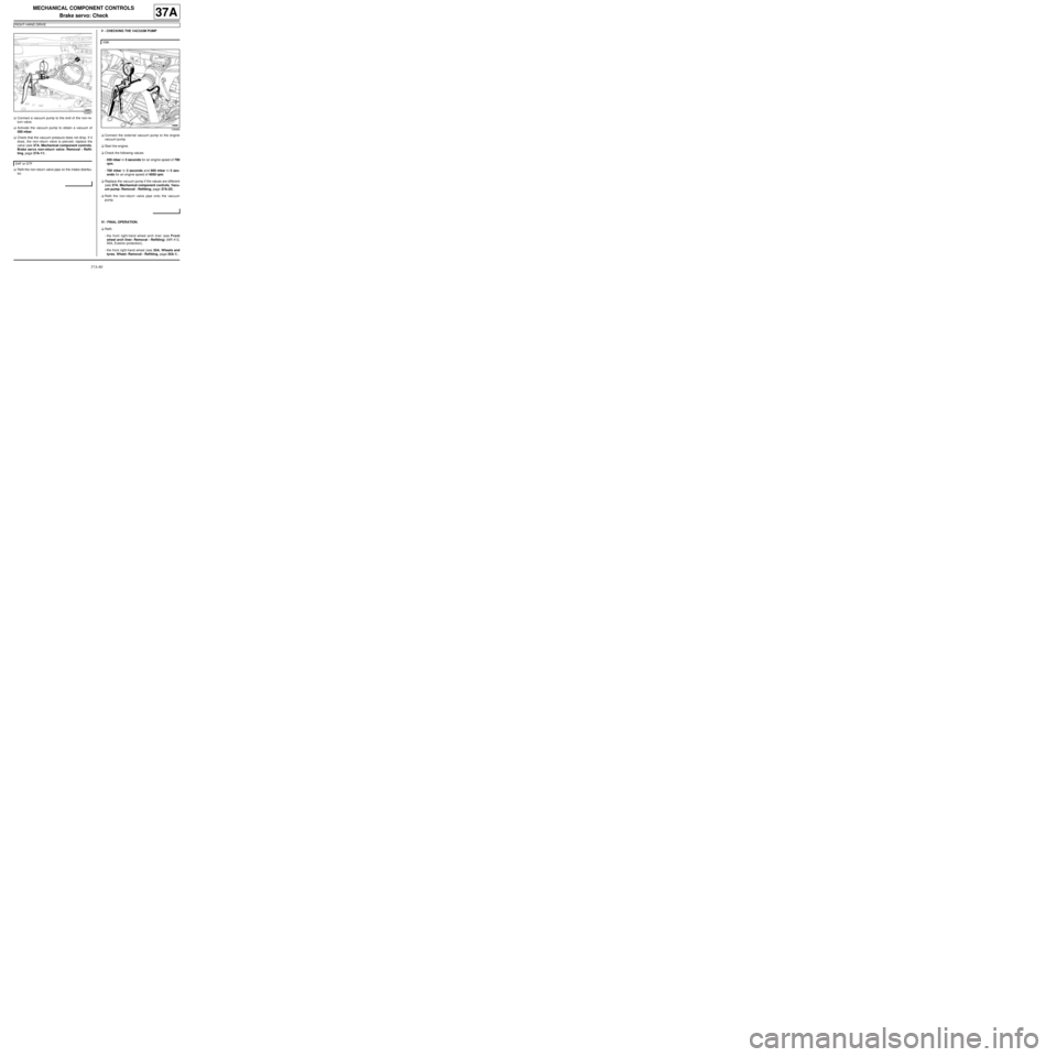
aConnect a vacuum pump to the end of the non-re-
turn valve.
aActivate the vacuum pump to obtain a vacuum of
500 mbar.
aCheck that the vacuum pressure does not drop. If it
does, the non-return valve is pierced; replace the
valve (see 37A, Mechanical component controls,
Brake servo non-return valve: Removal - Refit-
ting, page 37A-11) .
aRefit the non-return valve pipe on the intake distribu-
tor.V - CHECKING THE VACUUM PUMP
aConnect the external vacuum pump to the engine
vacuum pump.
aStart the engine.
aCheck the following values:
-550 mbar in 5 seconds for an engine speed of 700
rpm,
-700 mbar in 3 seconds and 900 mbar in 5 sec-
onds for an engine speed of 4050 rpm.
aReplace the vacuum pump if the values are different
(see 37A, Mechanical component controls, Vacu-
um pump: Removal - Refitting, page 37A-25) .
aRefit the non-return valve pipe onto the vacuum
pump.
VI - FINAL OPERATION.
aRefit:
-the front right-hand wheel arch liner (see Front
wheel arch liner: Removal - Refitting) (MR 412,
55A, Exterior protection),
-the front right-hand wheel (see 35A, Wheels and
tyres, Wheel: Removal - Refitting, page 35A-1) .
123907
D4F or D7F
K9K
106889