engine RENAULT TWINGO 2009 2.G Chasiss Workshop Manual
[x] Cancel search | Manufacturer: RENAULT, Model Year: 2009, Model line: TWINGO, Model: RENAULT TWINGO 2009 2.GPages: 281
Page 30 of 281
30A-26
GENERAL INFORMATION
Underbody heights: Adjustment value
30A
W1 = 158 mm ±± ± ±
8 mm
W2 = 270.7 mm ±± ± ±
12 mm
W1 = 163.5 mm ±± ± ±
8 mm
W2 = 275.1 mm ±± ± ±
12 mm
W1 = 157.7 mm ±± ± ±
8 mm
W2 = 270.3 mm ±± ± ±
12 mm EQUIPMENT LEVEL SPORT, and 16" ALUMIN-
IUM WHEELS
EQUIPMENT LEVEL SPORT, and 17" ALUMIN-
IUM WHEELS, and WITHOUT ADDITIONAL
SPORT PACK
EQUIPMENT LEVEL SPORT, and 17" ALUMIN-
IUM WHEELS, and ADDITIONAL EXTREME PACK
Note:
The position of the vehicle varies according to:
-the weight of the engine,
-the springs and shock absorbers,
-the tyres,
-the amount of fuel in the tank.
Page 86 of 281
31A-43
FRONT AXLE COMPONENTS
Front axle subframe: Removal - Refitting
31A
REMOVAL
I - REMOVAL PREPARATION OPERATION
aPosition the vehicle on a two-post lift (see Vehicle:
Towing and lifting) (02A, Lifting equipment).
aRemove:
-the front wheels (see 35A, Wheels and tyres,
Wheel: Removal - Refitting, page 35A-1) ,
-the front wheel arch liners (see Front wheel arch
liner: Removal - Refitting) (55A, Exterior protec-
tion).II - OPERATION FOR REMOVAL OF PART
CONCERNED
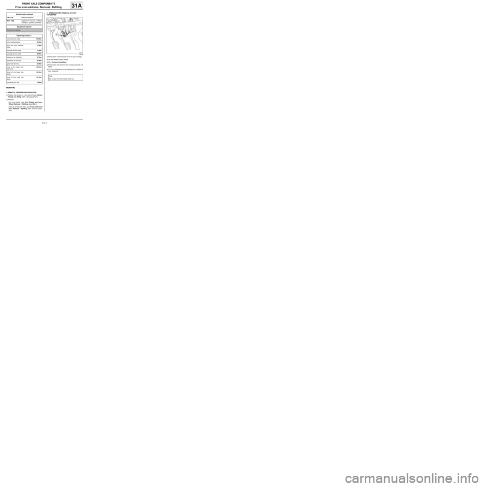
aRemove the universal joint cover (1) (do not keep).
aSet the wheels straight ahead.
aFit a flywheel immobiliser.
aRemove the bolt (2) from the universal joint (do not
keep).
aTilt the universal joint on the steering box to detach it
from the pinion. Special tooling required
Tav. 476Ball joint extractor.
Mot. 1390Suppor t for removal - refitting
of engine - gearbox assembly
Equipment required
flywheel immobiliser
Tightening torquesm
rear subframe bolts105 Nm
front subframe bolts62 Nm
front end cross member
bolts21 Nm
acoustic tie-rod bolts21 Nm
acoustic tie-rod bolts90 Nm
subframe tie-rod bolts21 Nm
subframe tie-rod nuts62 Nm
gear lever arm nut28 Nm
nuts of the lower arm
ball joints62 N.m
bolts of the lower ball
joints62 N.m
nuts of the track rod
ends37 N.m
universal joint bolt24 Nm
119544
Note:
Do not pull the intermediate shaft out.
Page 89 of 281
31A-46
FRONT AXLE COMPONENTS
Front axle subframe: Removal - Refitting
31A
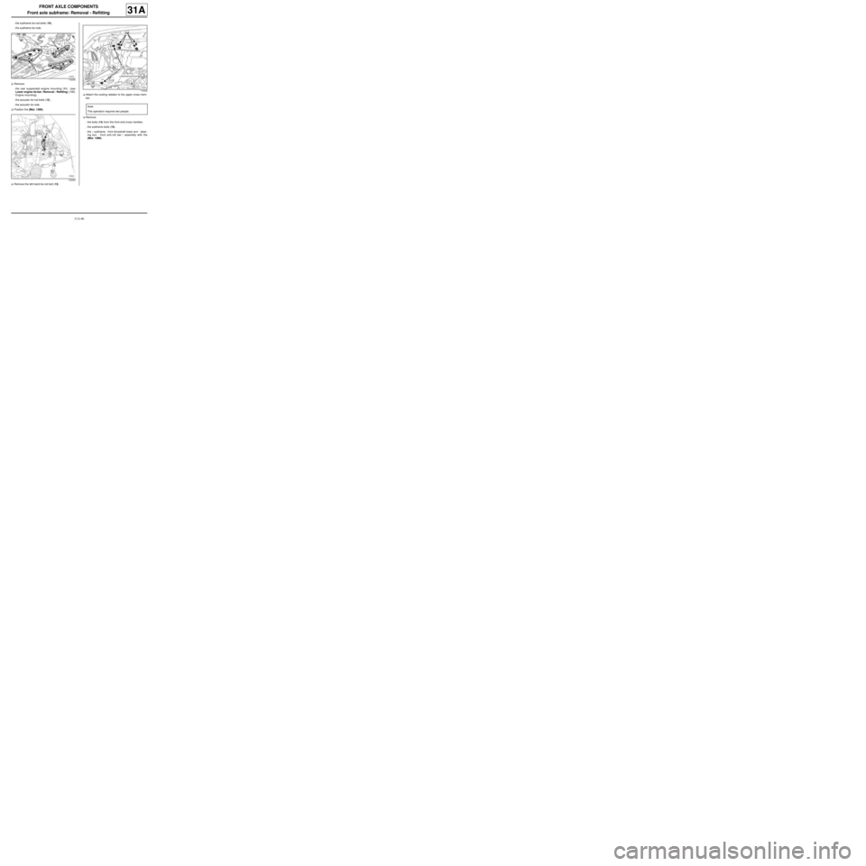
-the subframe tie-rod bolts (10) ,
-the subframe tie-rods.
aRemove:
-the rear suspended engine mounting (11) (see
Lower engine tie-bar: Removal - Refitting) (19D,
Engine mounting),
-the acoustic tie-rod bolts (12) ,
-the acoustic tie rods.
aPosition the (Mot. 1390).
aRemove the left-hand tie-rod bolt (13) .aAttach the cooling radiator to the upper cross mem-
ber.
aRemove:
-the bolts (14) from the front end cross member,
-the subframe bolts (15) ,
-the « subframe - front driveshaft lower arm - steer-
ing box - front anti-roll bar » assembly with the
(Mot. 1390).
119335
132029
119336
Note:
This operation requires two people.
Page 91 of 281
31A-48
FRONT AXLE COMPONENTS
Front axle subframe: Removal - Refitting
31A
II - REFITTING OPERATION FOR PART
CONCERNED
aRefit the speed selection cable guide on the sub-
frame.
aRefit:
-the front driveshaft lower arms (see 31A, Front
axle components, Front driveshaft lower arm:
Removal - Refitting, page 31A-33) ,
-the front anti-roll bar (see 31A, Front axle compo-
nents, Front anti-roll bar: Removal - Refitting,
page 31A-52) ,
-the steering box (see 36A, Steering assembly,
Steering box: Removal - Refitting, page 36A-1) .
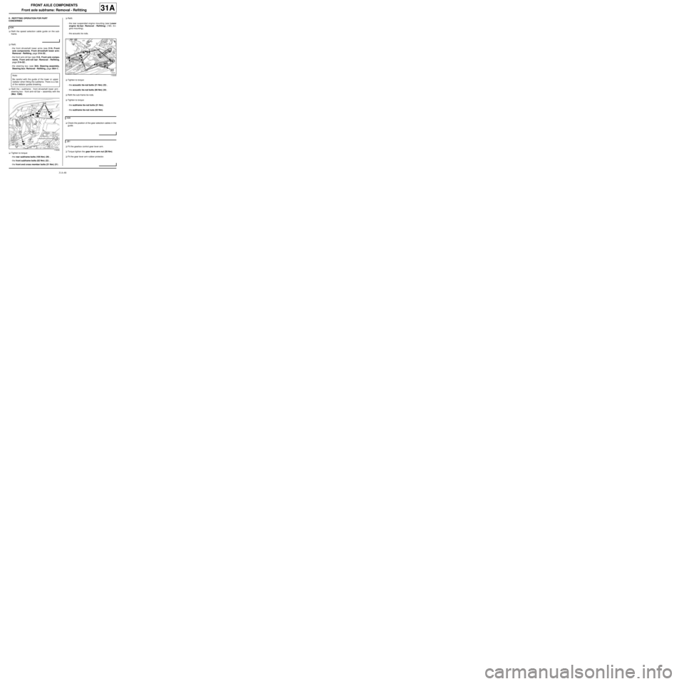
aRefit the « subframe - front driveshaft lower arm -
steering box - front anti-roll bar » assembly with the
(Mot. 1390).
aTighten to torque:
-the rear subframe bolts (105 Nm) (20) ,
-the front subframe bolts (62 Nm) (22) ,
-the front end cross member bolts (21 Nm) (21) .aRefit:
-the rear suspended engine mounting (see Lower
engine tie-bar: Removal - Refitting) (19D, En-
gine mounting),
-the acoustic tie rods.
aTighten to torque:
-the acoustic tie-rod bolts (21 Nm) (23) ,
-the acoustic tie-rod bolts (90 Nm) (24) .
aRefit the sub-frame tie-rods.
aTighten to torque:
-the subframe tie-rod bolts (21 Nm),
-the subframe tie-rod nuts (62 Nm).
aCheck the position of the gear selection cables in the
guide.
aFit the gearbox control gear lever arm.
aTorque tighten the gear lever arm nut (28 Nm).
aFit the gear lever arm rubber protector. K9K
Note:
Be careful with the guide of the lower or upper
radiator when fitting the subframe. There is a risk
of the radiator guides breaking.
119336
119335
K9K
JB1
Page 95 of 281
31A-52
FRONT AXLE COMPONENTS
Front anti-roll bar: Removal - Refitting
EQ UIPMENT LEVEL EA0 or EQUIPMENT LEVEL EA1 or EQUIPMENT LEVEL EA3 or EQUIPMENT LEVEL EA5
or EQUIPMENT LEVEL EAG or EQUIPMENT LEVEL EZ2 or EQUIPMENT LEVEL EZ4
31A
Anti-roll bar specifications:
REMOVAL
I - REMOVAL PREPARATION OPERATION
aPosition the vehicle on a two-post lift (see Vehicle:
Towing and lifting) (02A, Lifting equipment).
aRemove the front axle subframe (see 31A, Front
axle components, Front axle subframe: Removal
- Refitting, page 31A-43) .II - OPERATION FOR REMOVAL OF PART
CONCERNED
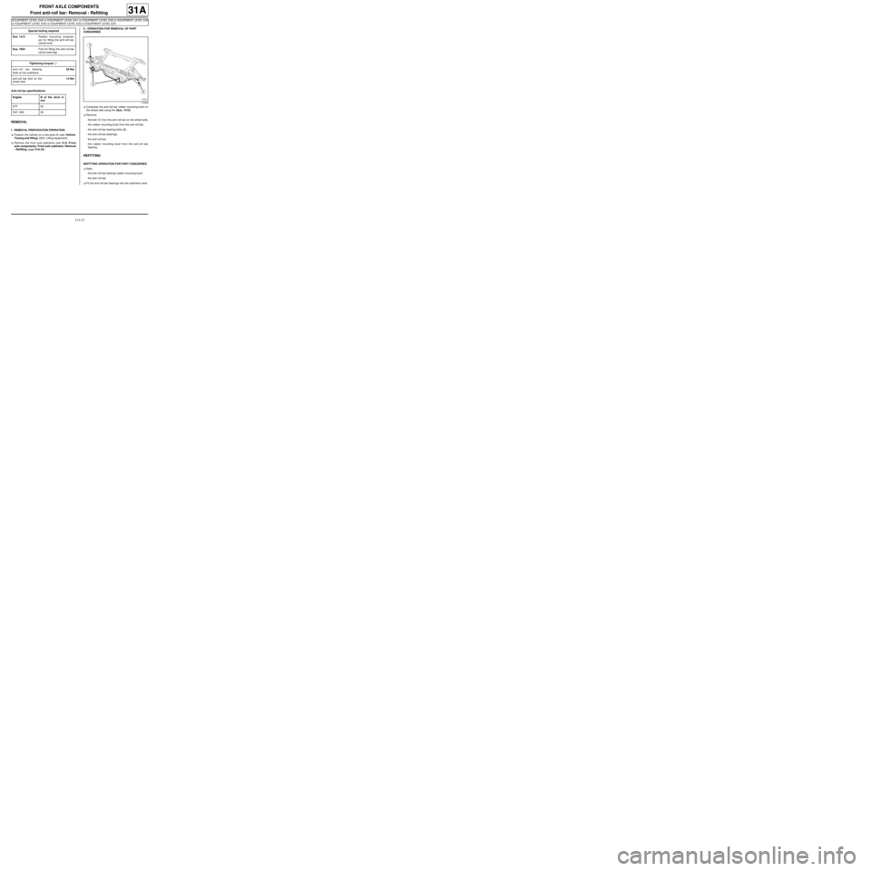
aCompress the anti-roll bar rubber mounting bush on
the wheel side using the (Sus. 1413).
aRemove:
-the bolt (1) from the anti-roll bar on the wheel side,
-the rubber mounting bush from the anti-roll bar,
-the anti-roll bar bearing bolts (2) ,
-the anti-roll bar bearings,
-the anti-roll bar,
-the rubber mounting bush from the anti-roll bar
bearing.
REFITTING
REFITTING OPERATION FOR PART CONCERNED
aRefit:
-the anti-roll bar bearing rubber mounting bush,
-the anti-roll bar.
aFit the anti-roll bar bearings into the subframe neck. Special tooling required
Sus. 1413Rubber mounting compres-
sor for fitting the anti-roll bar.
(wheel end).
Sus. 1824Fork for fitting the anti-roll bar
centre bearings.
Tightening torquesm
anti-roll bar bearing
bolts on the subframe35 Nm
anti-roll bar bolt on the
wheel side14 Nm
Engine Ø of the strut in
mm
D7F 25
D4F, K9K 26
119406
Page 135 of 281
33A-37
REAR AXLE COMPONENTS
Complete rear axle system: Removal - Refitting
33A
REMOVAL
I - REMOVAL PREPARATION OPERATION
aPosition the vehicle on a two-post lift ( (see Vehicle:
Towing and lifting) ).
aRelease the parking brake.
aFit the pedal press on the brake pedal to limit the
amount of brake fluid running out.
aRemove the rear wheels (see 35A, Wheels and ty-
res, Wheel: Removal - Refitting, page 35A-1) .II - OPERATION FOR REMOVAL OF PART
CONCERNED
1 - Removal
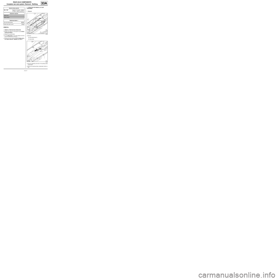
aRemove:
-the heat shield clips (1) ,
-the heat shield.
aUndo the adjusting screw (2) of the parking brake
compensator.
aRemove the parking brake compensator brake ca-
bles. Special tooling required
Mot. 1390Suppor t for removal - refitting
of engine - gearbox assembly
Equipment required
pedal press
safety strap(s)
Tightening torquesm
rear axle bearing bolts62 Nm
brake hose lower unions17 Nm
119435
119436
Page 150 of 281
35A-10
WHEELS AND TYRES
Tyre pressure: Identification
35A
INFLATION
The pressure values given are « motorway » pres-
sures.WARNING
If checking the pressure when hot, increase the tyre
inflation pressure by 0.2 to 0.3 bar above the rec-
ommended pressure.
Engine Wheel rim TyreTyre inflation pressure when cold (bar)
Front Rear emergency
spare wheel
D4F
D7F5.5 J 14165/65 R14 79T
2.2 2.0 2.2 175/65 R14 82 T
6 J 15 185/55 R15 82H
K9K5.5 J 14165/65 R14 79T 2.3 2.1 2.3
175/65 R14 82 T
2.2 2.0 2.2
6 J 15 185/55 R15 82H
Page 162 of 281
36A-11
STEERING ASSEMBLY
Steering column: Removal - Refitting
RIGHT-HAND DRIVE
36A
REMOVAL
I - REMOVAL PREPARATION OPERATION
aUnlock the steering column.
a
Lock the airbag computer using the Diagnostic tool
(see Fault finding - Replacement of components)
(MR 413, 88C, Airbags and seat belt pretensioners).
aDisconnect the battery (see Battery: Removal - Re-
fitting) (MR 411, 80A, Battery).
aRemove:
-the driver's front airbag (see Driver's frontal air-
bag: Removal - Refitting) (MR 411, 88C, Airbags
and pretensioners),
-the steering wheel (see 36A, Steering assembly,
Steering wheel: Removal - Refitting, page 36A-
23) .aRemove the rev counter (see Rev counter: Remov-
al - Refitting) (MR 411, 83A, Instrument panel).
aRemove:
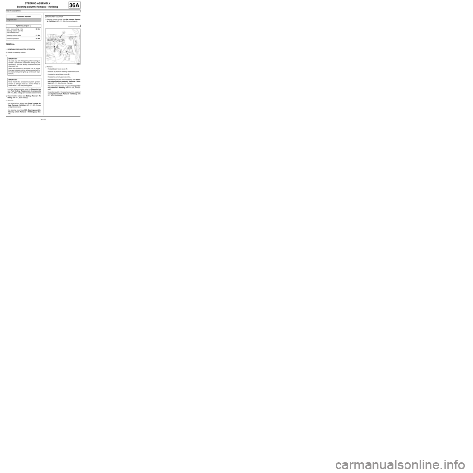
-the dashboard lower cover (1) ,
-the bolts (2) from the steering wheel lower cover,
-the steering wheel lower cover (3) ,
-the steering wheel upper cover (4) ,
-the steering column switch assembly (see Steer-
ing column switch assembly: Removal - Refit-
ting) (MR 411, 84A, Control - Signals),
-the antenna/transponder ring (see Transponder
ring: Removal - Refitting) (MR 411, 82A, Immobi-
liser),
-the ignition switch if the steering column is replaced
(see Ignition switch: Removal - Refitting) (MR
411, 82A, Immobiliser). Equipment required
Diagnostic tool
Tightening torquesm
bolt connecting the
steer ing column and the
inter mediate shaft30 Nm
steer ing column bolts21 Nm
universal joint bolt24 Nm
IMPORTANT
To avoid any risk of triggering when working on
or near a pyrotechnic component (airbags or pre-
tensioners), lock the airbag computer using the
diagnostic tool.
When this function is activated, all the trigger
lines are inhibited and the airbag warning light on
the instrument panel lights up continuously (igni-
tion on).
IMPORTANT
Never handle the pyrotechnic systems (preten-
sioners or airbags) near to a source of heat or
naked flame - they may be triggered.
ENGINE REV COUNTER
123870
Page 166 of 281
36A-15
STEERING ASSEMBLY
Steering column: Removal - Refitting
RIGHT-HAND DRIVE
36A
-the steering wheel lower cover,
-the steering wheel lower cover bolts,
-the dashboard lower cover.
aRefit the rev counter (see Rev counter: Removal -
Refitting) (MR 411, 83A, Instrument panel).
aRefit:
-the steering wheel (see 36A, Steering assembly,
Steering wheel: Removal - Refitting, page 36A-
23) ,
-the driver's front airbag (see Driver's frontal air-
bag: Removal - Refitting) (MR 411, 88C, Airbags
and pretensioners).
aConnect the battery (see Battery: Removal - Refit-
ting) (MR 411, 80A, Battery).
a
Unlock the airbag computer using the Diagnostic
tool (see Fault finding - Replacement of compo-
nents) (MR 413, 88C, Airbags and pretensioners). ENGINE REV COUNTER
IMPORTANT
To avoid a fault with or even triggering of pyro-
technic components (airbags or pretensioners),
check the airbag computer using the diagnostic
tool.
Page 193 of 281
37A-14
MECHANICAL COMPONENT CONTROLS
Brake servo: Removal - Refitting
JB1 or JH1 or JH3 or JR5, and LEFT-HAND DRIVE
37A
REMOVAL
I - REMOVAL PREPARATION OPERATION
aPosition the vehicle on a two-post lift (see Vehicle:
Towing and lifting) (02A, Lifting equipment).
aRemove the battery (see Battery: Removal - Refit-
ting) (80A, Battery).
aRemove the gearbox computer (see Sequential
gearbox converter: Removal - Refitting) (21B,
Sequential gearbox).
aRemove the battery tray (see Battery tray: Remov-
al - Refitting) (80A, Battery).
aRemove the petrol injection computer (see Petrol
injection computer: Removal - Refitting) (17B,
Petrol injection).
aRemove the diesel injection computer (see Diesel
injection computer: Removal - Refitting) (13B,
Diesel injection).
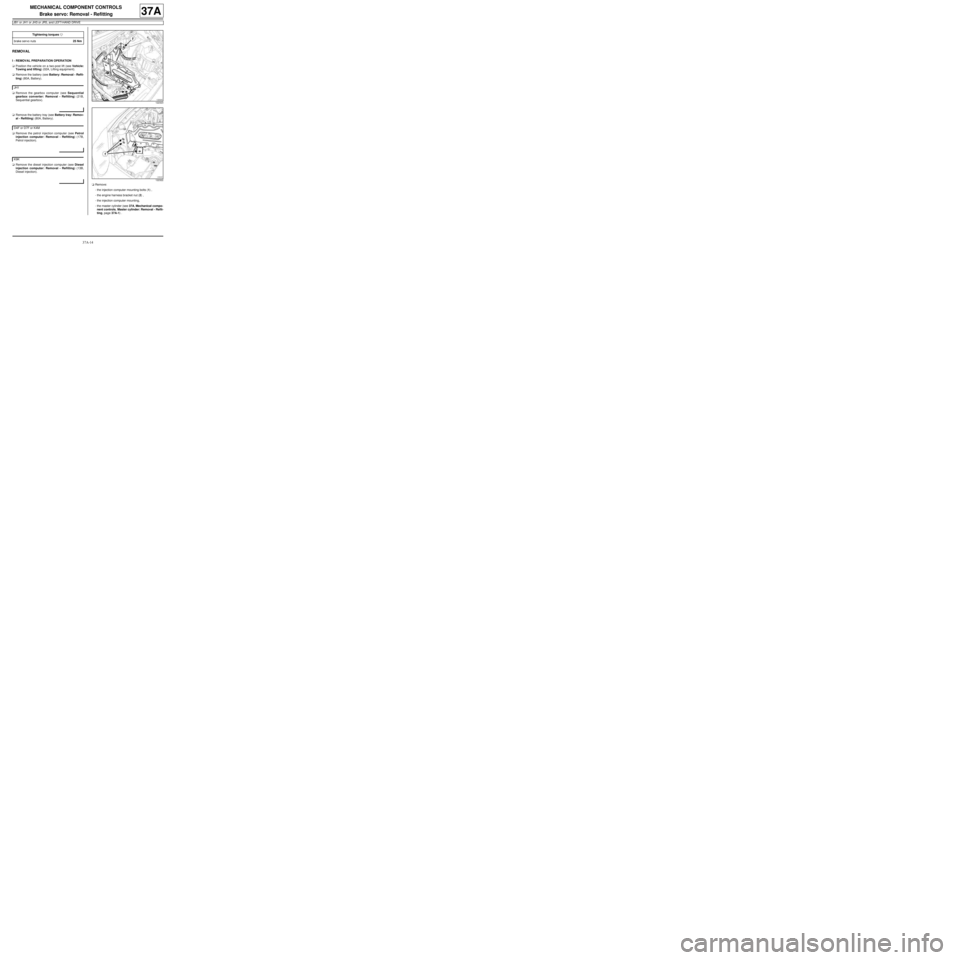
aRemove:
-the injection computer mounting bolts (1) ,
-the engine harness bracket nut (2) ,
-the injection computer mounting,
-the master cylinder (see 37A, Mechanical compo-
nent controls, Master cylinder: Removal - Refit-
ting, page 37A-1) . Tightening torquesm
brake servo nuts25 Nm
JH1
D4F or D7F or K4M
K9K
122323
122322