ESP RENAULT TWINGO 2009 2.G Chasiss Workshop Manual
[x] Cancel search | Manufacturer: RENAULT, Model Year: 2009, Model line: TWINGO, Model: RENAULT TWINGO 2009 2.GPages: 281
Page 20 of 281
30A-16
GENERAL INFORMATION
Rigid brake pipe: Repair
30A
a
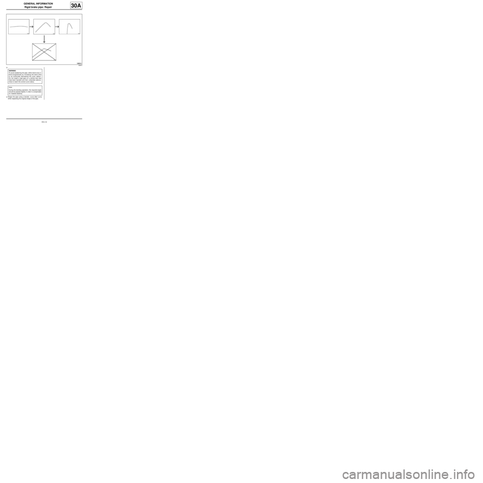
aShape the pipe using a bender, curve after curve,
while respecting the original shape of the pipe.
128814
WARNING
To avoid weakening the pipe, either bend once or
bend progressively by increasing the bend (that
is, by continually decreasing the curve radius).
Do not install a rigid pipe on a vehicle that may
have been bended and then unbended alterna-
tively to reach the correct curve radius.
Note:
During the bending operation, the required angle
should be passed slightly in order to compensate
for material elasticity.
Page 21 of 281
30A-17
GENERAL INFORMATION
Rigid brake pipe: Repair
30A
V - CHECKING BENDING
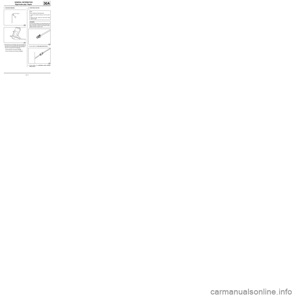
aCheck the out-of-roundness of the outer diameter at
the centre of the curve radius (2) using a sliding cal-
liper (the out-of-roundness of the outer diameter is
correct if it is less than 10% flattening):
-nominal diameter of the pipe: 4.75 mm,
-minimum diameter after bending: 4.30 mm.VI - REFITTING THE PIPE
a
aTorque tighten the brake pipe bolts (8 N.m).
aTorque tighten the underbody unions (female/
male) (6 N.m).
128664
128670
Note:
When refitting the rigid brake pipe:
-respect the original routing as much as possi-
ble,
-adjust the pipe routing by hand when fitting
inside the clips.
WARNING
Contact points between the rigid brake pipe and
the surrounding components could cause dam-
age to the pipe. In order to avoid these contacts,
adjust the pipe routing by hand.
128644
128646
Page 22 of 281
30A-18
GENERAL INFORMATION
Brake fluid: Specifications
30A
BRAKE FLUID REPLACEMENT INTERVAL
Our braking technology, and in particular the disc
brakes (hollow pistons which conduct little heat, have a
low volume of fluid in the cylinder, sliding callipers
avoiding the need for a fluid reserve in the least cooled
area of the wheel), has allowed us to prevent the risk of
« vapour lock » as far as possible, even with heavy
braking (mountainous area). However, current brake
fluids are subject to minor deterioration during the first
months of use due to slight humidity intake. This is why
it is recommended that you change the brake fluid: see
maintenance booklet for the vehicle.
1 - Topping up the level
Wear of the brake pads will result in a gradual drop in
the fluid level in the reservoir.
Do not top up the fluid, as the level will rise again when
the pads are next changed. The brake fluid level must
not fall below the minimum mark.
2 - Approved brake fluid
Mixing two incompatible brake fluids in the brake circuit
may lead to:
-serious risk of leakage due mainly to deterioration of
the cups,
-deterioration in the operation of the ESP system.
To prevent such risks, it is essential to use only brake
fluids that comply with the RENAULT standard (see
Vehicle: Parts and consumables for the repair) .
Page 74 of 281
31A-31
FRONT AXLE COMPONENTS
Front shock absorber and spring: Removal - Refitting31A
a
II - REFITTING OPERATION FOR PART
CONCERNED
aPlace the spring compressor tool in the vice fitted
with jaws.
aCompress the spring.
aInsert the spring in the neck of the cup.aRespect the order and direction of fitting for the con-
stituent parts.
aTorque tighten the new shock absorber rod nut
(62 N.m).
aDecompress the spring.
aRemove the spring compressor tool.
aRefit:
-the « spring/shock absorber » assembly,
-the shock absorber cup,
-the shock absorber nut cover.
aRemove the safety strap(s).
aRefit:
-the shock absorber base bolts,
-the shock absorber base nuts,
-the wheel speed sensor wiring bracket,
-the bolt of the wheel speed sensor wiring bracket.
aTighten to torque:
-the new shock absorber base nuts (105 N.m),
-the wheel speed sensor wiring bracket bolt (8
N.m). RIGHT-HAND DRIVE
139405
WARNING
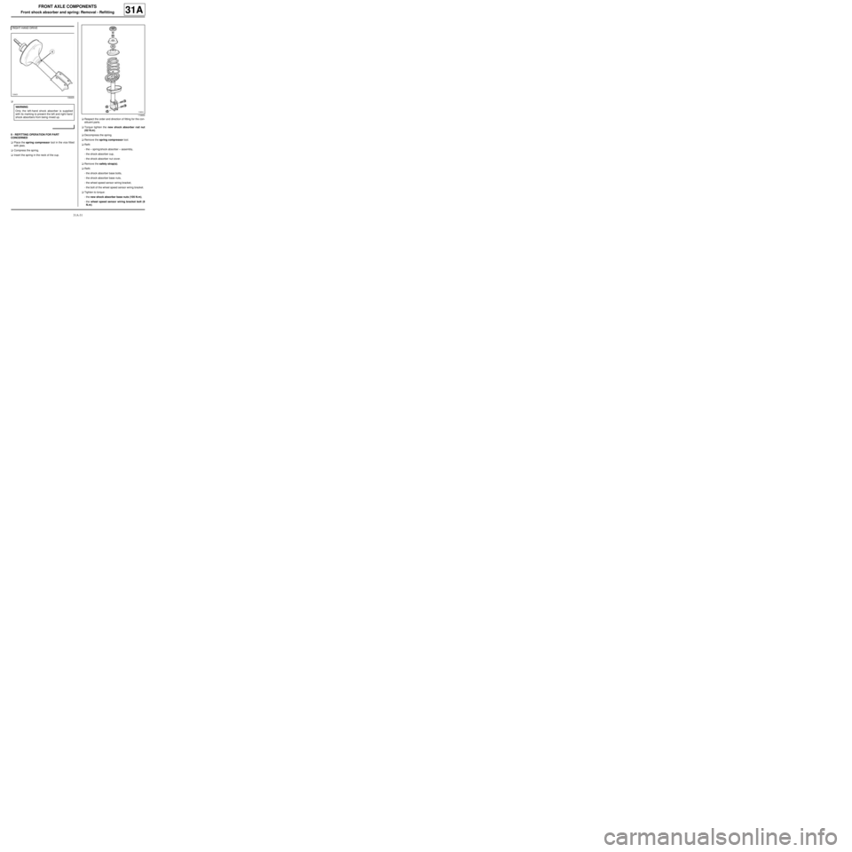
Only the left-hand shock absorber is supplied
with its marking to prevent the left and right-hand
shock absorbers from being mixed up.
119654
Page 146 of 281
35A-6
WHEELS AND TYRES
Wheel: Balancing
35A
aEnter the specific wheel parameters when starting
the wheel balancer.
aStart the wheel balancer and check the wheel bal-
ance, which should be 0 g on each plane of the
wheel.
aIf this is not the case, remove the old wheel balanc-
ing weights and repeat the wheel balancing proce-
dure, checking that the wheel balance equals 0 on
each wheel plane.
IV - FINAL OPERATION
aRefit the wheel (see 35A, Wheels and tyres,
Wheel: Removal - Refitting, page 35A-1) . WARNING
To avoid detachment of the balance weights, use
only weights which correspond to the vehicle
wheel rims.
Page 209 of 281
37A-30
MECHANICAL COMPONENT CONTROLS
Accelerator pedal: Removal - Refitting
37A
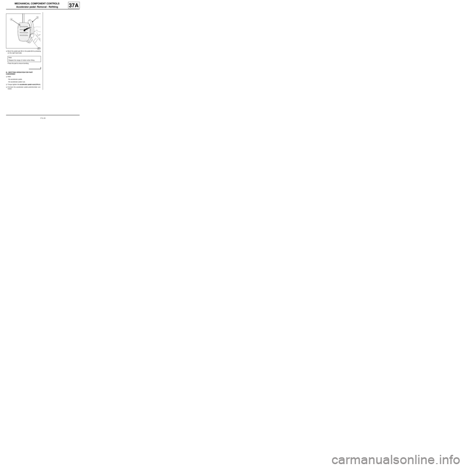
aBond the pedal pad (3) to the pedal (4) by pressing
on the right-hand side.
Press the pad to ensure bonding.
III - REFITTING OPERATION FOR PART
CONCERNED
aRefit:
-the accelerator pedal,
-the accelerator pedal nuts.
aTorque tighten the accelerator pedal nuts (8 N.m ).
aConnect the accelerator pedal potentiometer con-
nector.
135017
Note:
Respect the range of motion when fitting.
Page 215 of 281
37A-36
MECHANICAL COMPONENT CONTROLS
Brake pedal: Removal - Refitting
RIGHT-HAND DRIVE, and 5-SPEED MANUAL GEARBOX
37A
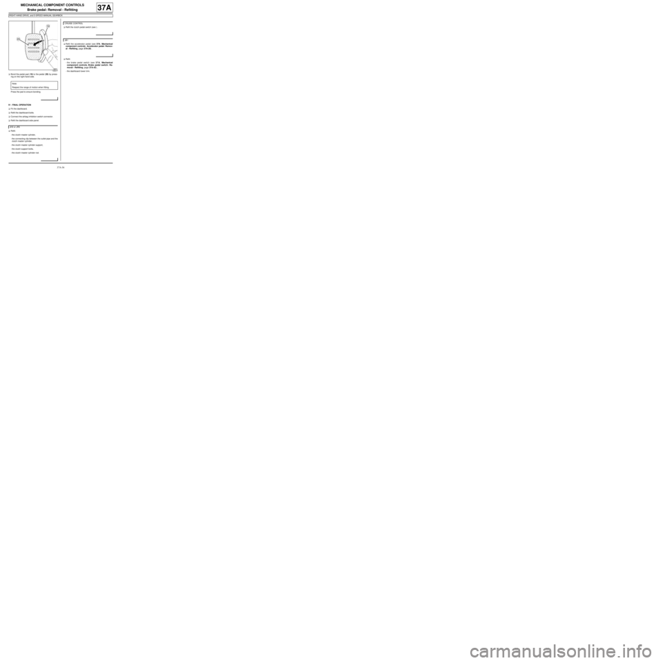
aBond the pedal pad (19) to the pedal (20) by press-
ing on the right-hand side.
Press the pad to ensure bonding.
IV - FINAL OPERATION
aFit the dashboard.
aRefit the dashboard bolts.
aConnect the airbag inhibition switch connector.
aRefit the dashboard side panel.
aRefit:
-the clutch master cylinder,
-the connecting clip between the outlet pipe and the
clutch master cylinder,
-the clutch master cylinder support,
-the clutch support bolts,
-the clutch master cylinder rod.aRefit the clutch pedal switch (see ) .
aRefit the accelerator pedal (see 37A, Mechanical
component controls, Accelerator pedal: Remov-
al - Refitting, page 37A-29) .
aRefit:
-the brake pedal switch (see 37A, Mechanical
component controls, Brake pedal switch: Re-
moval - Refitting, page 37A-42) ,
-the dashboard lower trim.
135017
Note:
Respect the range of motion when fitting.
JH3 or JR5
CRUISE CONTROL
JB1
Page 220 of 281
37A-41
MECHANICAL COMPONENT CONTROLS
Brake pedal: Removal - Refitting
LEFT-HAND DRIVE, and 5-SPEED MANUAL GEARBOX
37A
III - REFITTING OPERATION FOR THE ALUMINIUM
PEDAL PADS
aCheck that the pedal is at ambient temperature.
aCheck that the surface of the pedal is clean.
aActivate the pedal bonding surface with some paper
soaked in HEPTANE.
Wipe immediately with a clean and dry cloth.
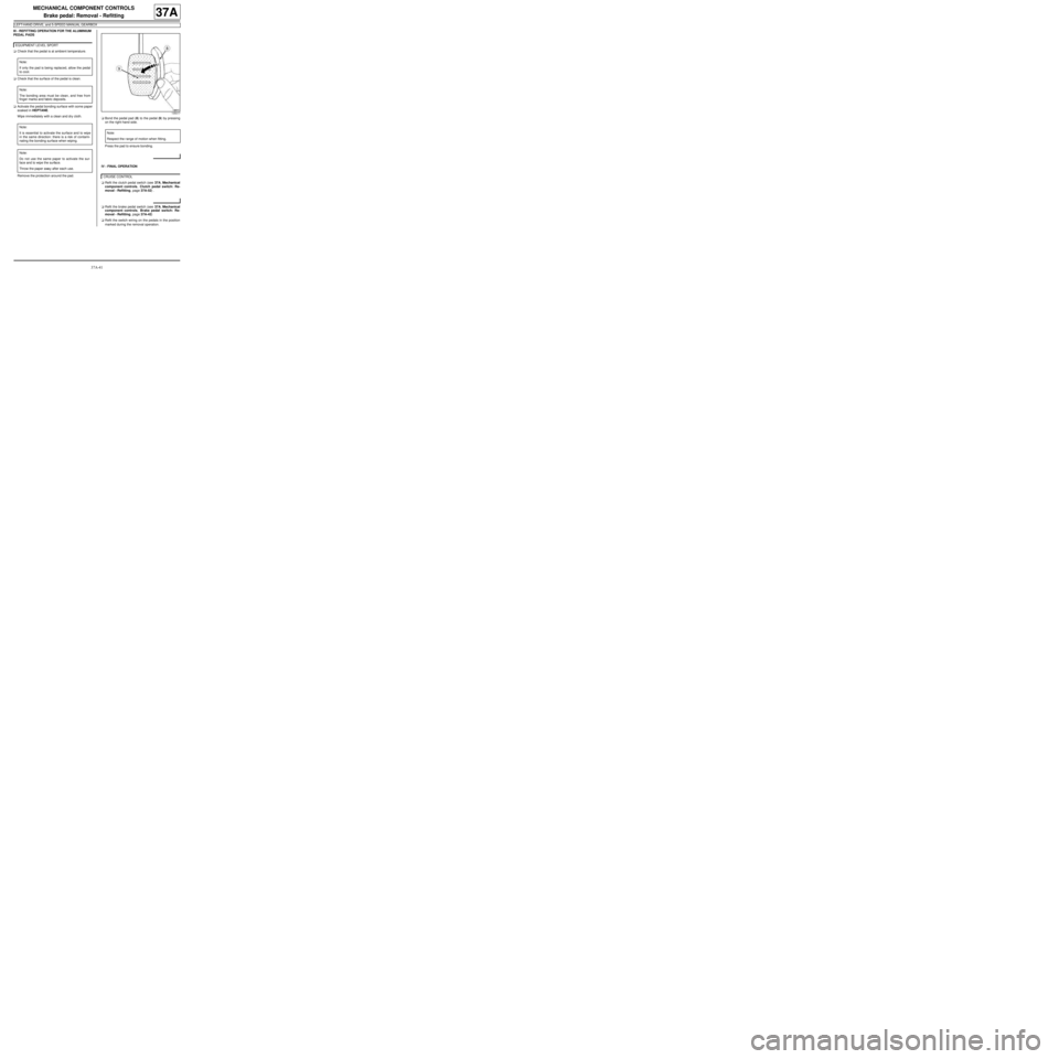
Remove the protection around the pad.aBond the pedal pad (8) to the pedal (9) by pressing
on the right-hand side.
Press the pad to ensure bonding.
IV - FINAL OPERATION
aRefit the clutch pedal switch (see 37A, Mechanical
component controls, Clutch pedal switch: Re-
moval - Refitting, page 37A-52) .
aRefit the brake pedal switch (see 37A, Mechanical
component controls, Brake pedal switch: Re-
moval - Refitting, page 37A-42)
aRefit the switch wiring on the pedals in the position
marked during the removal operation. EQ UIPMENT LEVEL SPORT
Note:
If only the pad is being replaced, allow the pedal
to cool.
Note:
The bonding area must be clean, and free from
finger marks and fabric deposits.
Note:
It is essential to activate the surface and to wipe
in the same direction: there is a risk of contami-
nating the bonding surface when wiping.
Note:
Do not use the same paper to activate the sur-
face and to wipe the surface.
Throw the paper away after each use.
135017
Note:
Respect the r ange of motion when fitting.
CRUISE CONTROL
Page 280 of 281
38C-21
ANTI-LOCK BRAKING SYSTEM
Braking computer: Removal - Refitting
38C
This repair method only relates to vehicles without
ESP, equipped with TEVES brand hydraulic unit.
REMOVAL
I - REMOVAL PREPARATION OPERATION
aPosition the vehicle on a two-post lift (see Vehicle:
Towing and lifting) (MR 411, 02A, Lifting equip-
ment).
aDisconnect the battery (see Battery: Removal - Re-
fitting) (MR 411, 80A, Battery).
aRemove the entire hydraulic unit (see 38C, Anti-
lock braking system, Hydraulic brake unit: Re-
moval - Refitting, page 38C-2) .II - OPERATION FOR REMOVAL OF PART
CONCERNED
aRemove:
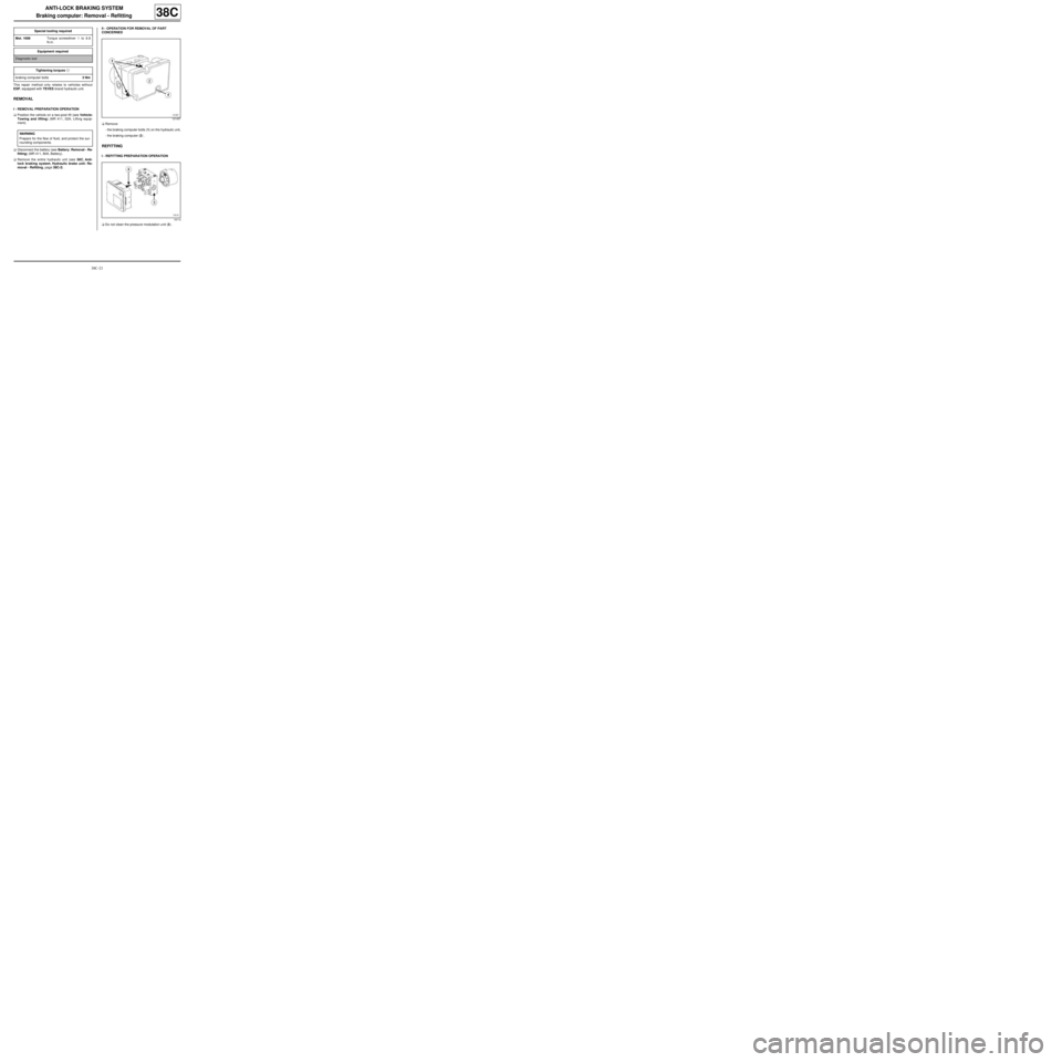
-the braking computer bolts (1) on the hydraulic unit,
-the braking computer (2) .
REFITTING
I - REFITTING PREPARATION OPERATION
aDo not clean the pressure modulation unit (3) . Special tooling required
Mot. 1608Torque screwdriver 1 to 6.6
N.m.
Equipment required
Diagnostic tool
Tightening torquesm
braking computer bolts3 Nm
WARNING
Prepare for the flow of fluid, and protect the sur-
rounding components.
121457
19113