tow RENAULT TWINGO 2009 2.G Chasiss Workshop Manual
[x] Cancel search | Manufacturer: RENAULT, Model Year: 2009, Model line: TWINGO, Model: RENAULT TWINGO 2009 2.GPages: 281
Page 6 of 281
30A-2
GENERAL INFORMATION
Brake circuit: Precautions for the repair
30A
I - SAFETY
1 - Advice to be followed before any operation
For an operation requiring the use of a lift, follow the
safety advice (see Vehicle: Towing and lifting) (02A,
Lifting equipment).
The brake regulation circuit must be free of all hydrau-
lic and electrical faults.
In case of incorrect handling, the brake fluid can cause
serious injury and damage. Follow the manufacturer's
instructions for brake fluid.
To prevent dust from entering the master cylinder res-
ervoir and the brake circuit, the plug must be removed
just before filling and closed immediately afterwards,
2 - Instructions to be followed during the operation
Do not press on the brake pedal during work on the
brake system.
If, during work on the brake system, any damage on
any part is observed, it must be repaired before driving
the vehicle again.
Brake fluid is highly corrosive. Ensure any brake fluid
spilt on parts of the vehicle is cleaned off.
Use brake fluids that comply with the Renault standard
(see Vehicle: Parts and consumables for the repair)
.
Check the brake fluid levels in the braking circuit and
the bleeding device.
Check that the pressure of the bleeding device is be-
tween 1.5 bar and 2 bar.
II - CLEANLINESS
1 - Advice to be followed before any operation
Protect any bodywork components that risk being dam-
aged by brake fluid with a cover.
2 - Instructions to be followed during the operation
Fit blanking plugs recommended for the Siemens K9K
injection system at the end of each pipe and in all the
openings of the disconnected components of the brake
circuit.
Clean around the braking system with BRAKE
CLEANER (see Vehicle: Parts and consumables
for the repair) (04B, Consumables - Products).Do not allow friction materials to come into contact with
grease, oil or other lubricants and cleaning products
which are mineral oil based.
III - GENERAL RECOMMENDATIONS
When replacing brake pads, always replace the pads
on the other side as well.
When replacing a disc, always replace the disc on the
opposite side.
When replacing brake discs, you must replace the
brake pads.
Always replace the rigid brake pipe clips.
Reminder:
-The pipes between the master cylinder, callipers and
the hydraulic assembly are connected using threaded
unions with a metric thread.
-Therefore, only parts specified in the Parts Catalogue
for this vehicle should be used. WARNING
Prepare for the flow of fluid, and protect the sur-
rounding components.
WARNING
In order not to damage the brake hose:
-do not tension the hose,
-do not twist the hose,
-check that there is no contact with the surrounding
components, regardless of the position of the
wheels.
IMPORTANT
To avoid any accident, br ing the pistons, brake pads
and brake discs into contact by depressing the
brake pad several times.
Page 8 of 281
30A-4
GENERAL INFORMATION
Braking circuit: Bleed
30A
This procedure must be applied after one of the fol-
lowing components has been removed or replaced:
-the master cylinder,
-the brake fluid,
-the hydraulic unit,
-a rigid pipe,
-a hose,
-the reservoir,
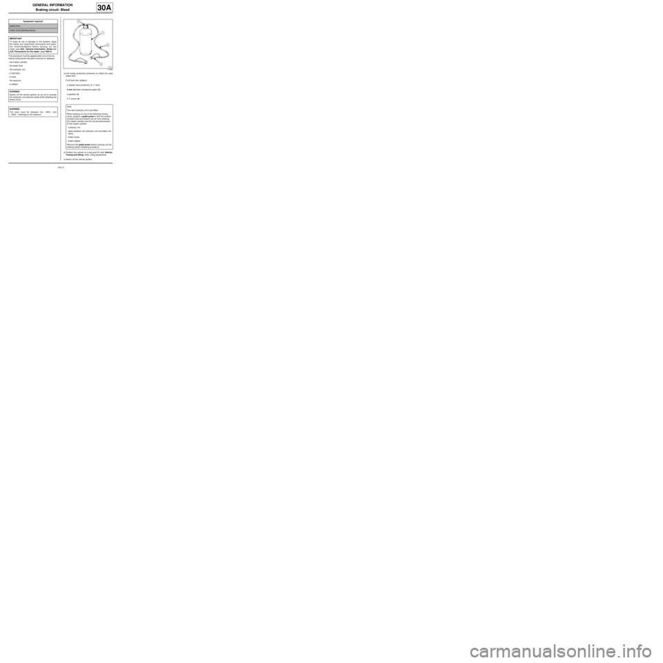
-a calliper.aUse locally produced containers to collect the used
brake fluid.
Front and rear callipers:
-2 washer fluid containers (1) (1 litre),
-4 mm diameter transparent pipes (2) ,
-4 pipettes (3) ,
-2 T-unions (4) .
aPosition the vehicle on a two-post lift (see Vehicle:
Towing and lifting) (02A, Lifting equipment).
aSwitch off the vehicle ignition. Equipment required
pedal press
brake circuit bleeding device
IMPORTANT
To avoid all risk of damage to the systems, apply
the safety and cleanliness instructions and opera-
tion recommendations before carrying out any
repair (see 30A, General information, Brake cir-
cuit: Precautions for the repair, page 30A-2) .
WARNING
Switch off the vehicle ignition so as not to activate
the hydraulic unit solenoid valves when bleeding the
brake circuit.
WARNING
The level must be between the « MIN » and
« MAX » markings on the reservoir.
115993
Note:
The new hydraulic unit is pre-filled.
When working on one of the following compo-
nents , position a pedal press to limit the outflow
of brake fluid and prevent any air from entering
the master cylinder and the circuits downstream
of the master cylinder:
-hydraulic unit,
-pipes between the hydraulic unit and brake cal-
lipers,
-brake hoses,
-brake calliper.
Remove the pedal press before carrying out the
braking system bleeding procedure.
Page 27 of 281
30A-23
GENERAL INFORMATION
Axle assemblies: Check
30A
aLock the slip plates of the lift.
aPosition the vehicle on a lift (see Vehicle: Towing
and lifting) .
aCheck the condition of the following components:
-track rods,
-axial ball joint linkages,
-subframe,
-lower arm rubber bushes,
-lower arm ball joints (see Front driveshaft lower
arm ball joint: Check) ,
-shock absorbers,
-tyres,
aCheck:
-the tyre size (see 35A, Wheels and tyres, Tyres:
Identification, page 35A-7) ,
-the tyre inflation pressure (see 35A, Wheels and
tyres, Tyre pressure: Identification, page 35A-
10) .
aPut the vehicle in the VODM position (vehicle in run-
ning order) (see 30A, General information, Under-
body heights: Adjustment value, page 30A-24) :
-tank full,
-vehicle empty (without luggage, etc.).
aConsult:
-the front axle geometry values (see 30A, General
information, Front axle assembly: Adjustment
values, page 30A-31) ,
-the rear axle geometry values (see 30A, General
information, Rear axle assembly: Adjustment
values, page 30A-38) .
aRefer to the user manual for the geometry tester.
aCheck the geometry using the geometry tester.
aIf there is an inconsistency between the manufactur-
er's values and the measured values:
aAdjust the front axle (see 30A, General informa-
tion, Front axle system: Adjustment, page 30A-
36)
Page 44 of 281
31A-1
FRONT AXLE COMPONENTS
Front brake pads: Removal - Refitting
EQ UIPMENT LEVEL EA0 or EQUIPMENT LEVEL EA1 or EQUIPMENT LEVEL EA3 or EQUIPMENT LEVEL EA5
or EQUIPMENT LEVEL EAG or EQUIPMENT LEVEL EZ2 or EQUIPMENT LEVEL EZ4
31A
When replacing brake pads, be sure to replace the
pads on the opposite side.
REMOVAL
I - OPERATION FOR REMOVAL OF PART
CONCERNED
aPosition the vehicle on a two-post lift (see Vehicle:
Towing and lifting) .
aSwitch off the ignition without removing the key to
keep the steering column unlocked.
aRemove the front wheels (see 35A, Wheels and ty-
res, Wheel: Removal - Refitting, page 35A-1) .
II - OPERATION FOR REMOVAL OF PART
CONCERNED
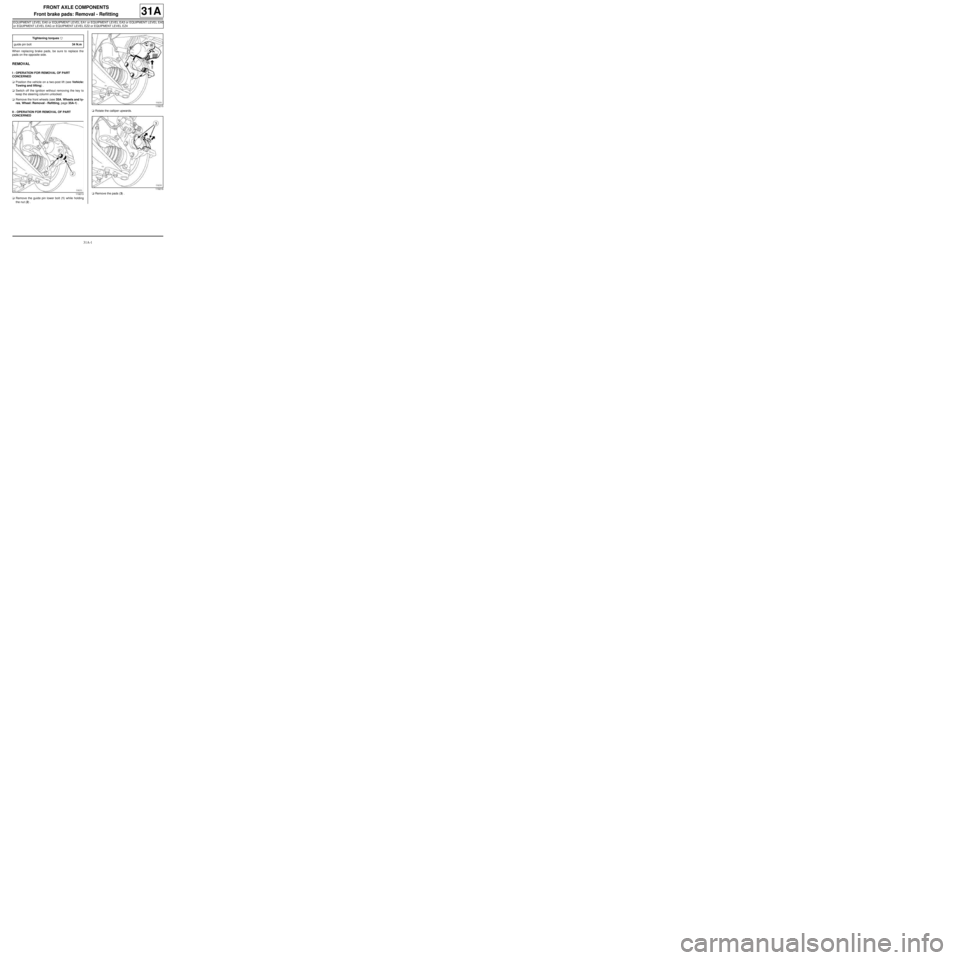
aRemove the guide pin lower bolt (1) while holding
the nut (2) .aRotate the calliper upwards.
aRemove the pads (3) . Tightening torquesm
guide pin bolt34 N.m
119213
119215
119216
Page 46 of 281
31A-3
FRONT AXLE COMPONENTS
Front brake pads: Removal - Refitting
EQ UIPMENT LEVEL SPORT
31A
REMOVAL
I - REMOVAL PREPARATION OPERATION
aPosition the vehicle on a two-post lift (see Vehicle:
Towing and lifting) (02A, Lifting equipment).
aSet the wheels straight ahead.
aRemove the front wheels (see 35A, Wheels and ty-
res, Wheel: Removal - Refitting, page 35A-1) .II - REMOVAL OPERATION
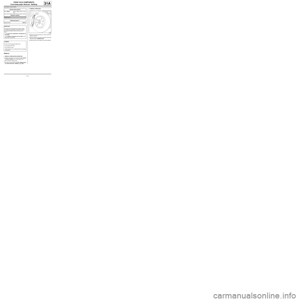
aRemove the retaining spring (1) using a wide, flat-
blade screwdriver.
aMark the position of the cap on the base of the shock
absorber using a indelible pencil.
aUnclip the cap from the base of the shock absorber. Special tooling required
Fre. 1190-01Brake calliper piston return
tool.
Equipment required
indelible pencil
Tightening torquesm
guide pin bolts28 N.m
IMPORTANT
To avoid all risk of damage to the systems, apply
the safety and cleanliness instructions and opera-
tion recommendations before carrying out any
repair:
- (see Front axle components: Precautions for
the repair) ,
- (see Vehicle: Precautions for the repair) (01D,
Mechanical introduction).
WARNING
In order not to damage the brake hose:
-do not tension the hose,
-do not twist the hose,
-check that there is no contact with the surrounding
components.
145122
Page 49 of 281
31A-6
FRONT AXLE COMPONENTS
Front brake hose: Removal - Refitting
31A
REMOVAL
I - REMOVAL PREPARATION OPERATION
aPosition the vehicle on a two-post lift (see Vehicle:
Towing and lifting) .
aSet the wheels straight ahead.
aPosition a pedal press on the brake pedal to limit
the outflow of brake fluid.
aRemove the front wheel (see 35A, Wheels and ty-
res, Wheel: Removal - Refitting, page 35A-1) .II - OPERATION FOR REMOVAL OF PART
CONCERNED
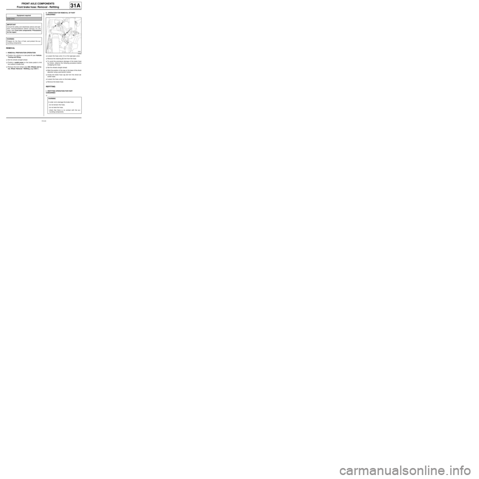
aLoosen the hose union (1) on the rigid pipe union.
aRemove the retaining (2) fork from the hose.
aTo avoid the premature damage of the brake hose
by friction, observe the following procedure before
unclipping the hose:
aSet the wheels straight ahead.
aMark the position of the cap on the base of the shock
absorber using a permanent marker.
aUnclip the brake hose cap (3) from the shock ab-
sorber base.
aLoosen the hose union on the brake calliper.
aRemove the brake hose.
REFITTING
I - REFITTING OPERATION FOR PART
CONCERNED
a Equipment required
pedal press
IMPORTANT
Consult the safety and cleanliness advice and oper-
ation recommendations before carrying out any
repair (see Front axle components: Precautions
for the repair) .
WARNING
Prepare for the flow of fluid, and protect the sur-
rounding components.
135304
WARNING
In order not to damage the brake hose:
-do not tension the hose,
-do not twist the hose,
-check that there is no contact with the sur-
rounding components.
Page 51 of 281
31A-8
FRONT AXLE COMPONENTS
Front brake calliper: Removal - Refitting
EQ UIPMENT LEVEL EA0 or EQUIPMENT LEVEL EA1 or EQUIPMENT LEVEL EA3 or EQUIPMENT LEVEL EA5
or EQUIPMENT LEVEL EAG or EQUIPMENT LEVEL EZ2 or EQUIPMENT LEVEL EZ4
31A
REMOVAL
I - REMOVAL PREPARATION OPERATION
aPosition the vehicle on a two-post lift (see Vehicle:
Towing and lifting) .
aFit the pedal press to the brake pedal to limit the
outflow of brake fluid.
aUnlock the steering column.
aRemove the front wheel on the side concerned (see
35A, Wheels and tyres, Wheel: Removal - Refit-
ting, page 35A-1) .II - OPERATION FOR REMOVAL OF PART
CONCERNED
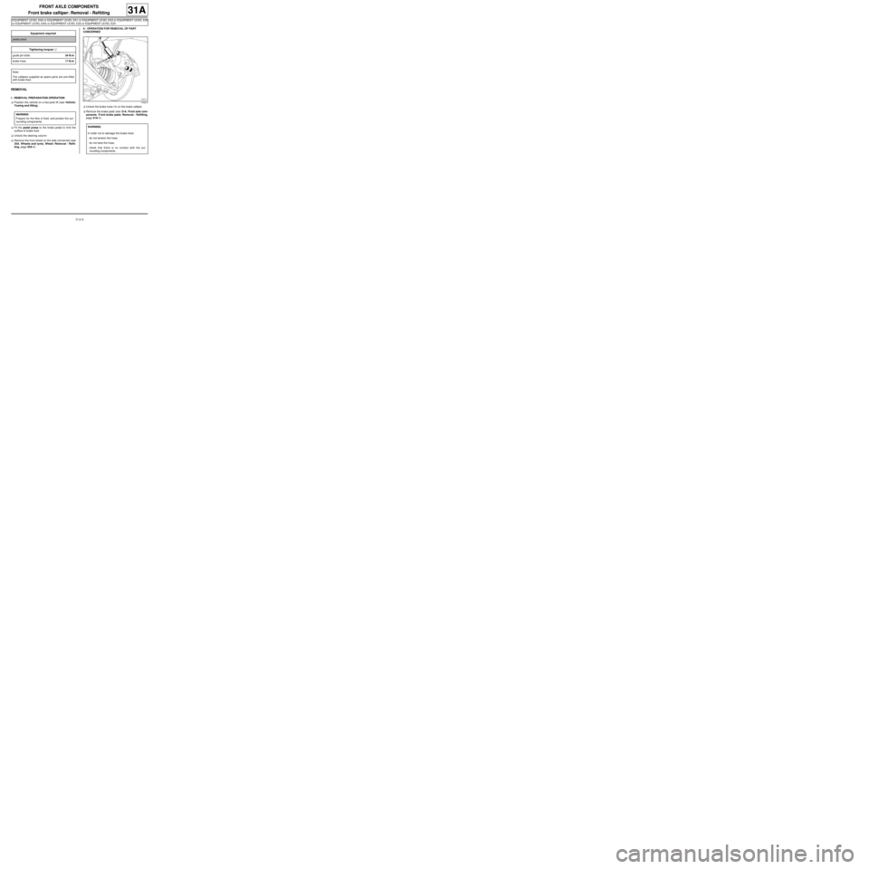
aUnlock the brake hose (1) on the brake calliper.
aRemove the brake pads (see 31A, Front axle com-
ponents, Front brake pads: Removal - Refitting,
page 31A-1) . Equipment required
pedal press
Tightening torquesm
guide pin bolts34 N.m
brake hose17 N.m
Note:
The callipers supplied as spare par ts are pre-filled
with br ake fluid.
WARNING
Prepare for the flow of fluid, and protect the sur-
rounding components.
119214
WARNING
In order not to damage the brake hose:
-do not tension the hose,
-do not twist the hose,
-check that there is no contact with the sur-
rounding components.
Page 53 of 281
31A-10
FRONT AXLE COMPONENTS
Front brake calliper: Removal - Refitting
EQ UIPMENT LEVEL SPORT
31A
REMOVAL
I - REMOVAL PREPARATION OPERATION
aPosition the vehicle on a two-post lift (see Vehicle:
Towing and lifting) (02A, Lifting equipment).
aRemove the front wheel (see 35A, Wheels and ty-
res, Wheel: Removal - Refitting, page 35A-1) .
aFit a pedal press on the brake pedal to limit the out-
flow of brake fluid.II - REMOVAL OPERATION
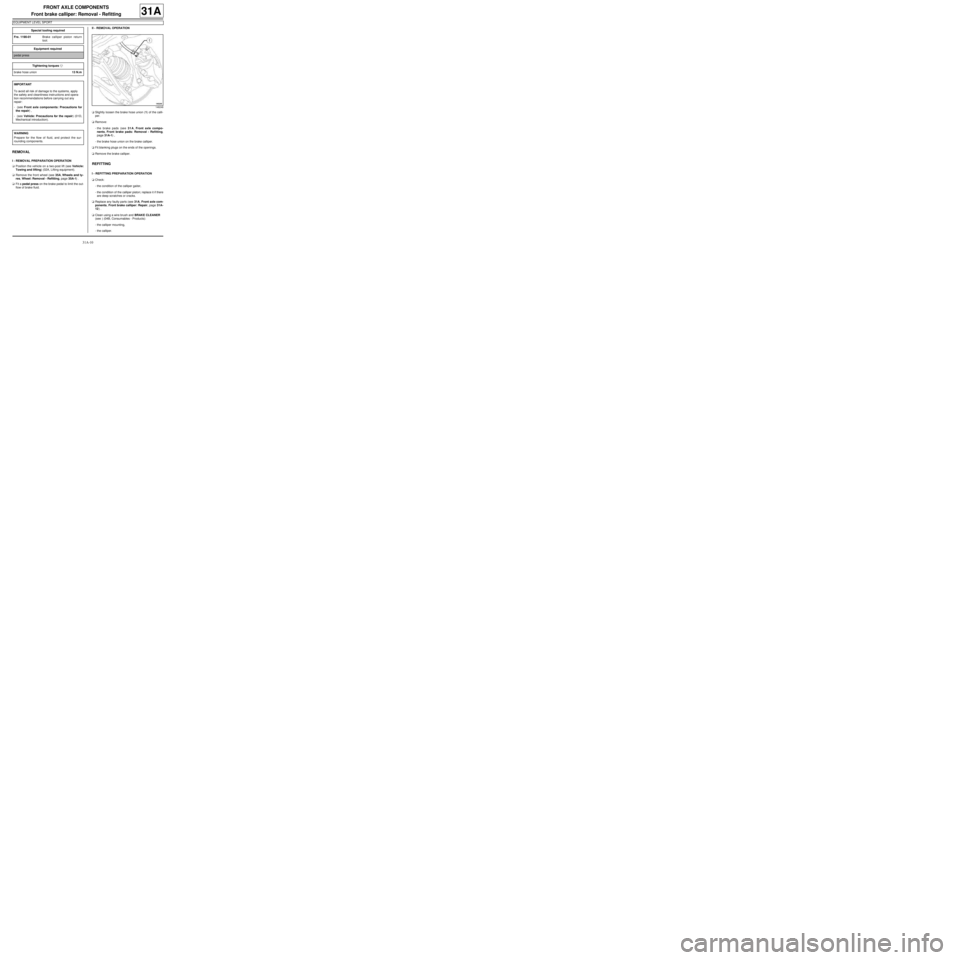
aSlightly loosen the brake hose union (1) of the calli-
per.
aRemove:
-the brake pads (see 31A, Front axle compo-
nents, Front brake pads: Removal - Refitting,
page 31A-1) ,
-the brake hose union on the brake calliper.
aFit blanking plugs on the ends of the openings.
aRemove the brake calliper.
REFITTING
I - REFITTING PREPARATION OPERATION
aCheck:
-the condition of the calliper gaiter,
-the condition of the calliper piston; replace it if there
are deep scratches or cracks.
aReplace any faulty parts (see 31A, Front axle com-
ponents, Front brake calliper: Repair, page 31A-
12) .
aClean using a wire brush and BRAKE CLEANER
(see ) (04B, Consumables - Products):
-the calliper mounting,
-the calliper. Special tooling required
Fre. 1190-01Brake calliper piston return
tool.
Equipment required
pedal press
Tightening torquesm
brake hose union13 N.m
IMPORTANT
To avoid all risk of damage to the systems, apply
the safety and cleanliness instructions and opera-
tion recommendations before carrying out any
repair:
- (see Front axle components: Precautions for
the repair) ,
- (see Vehicle: Precautions for the repair) (01D,
Mechanical introduction).
WARNING
Prepare for the flow of fluid, and protect the sur-
rounding components.
146248
Page 55 of 281
31A-12
FRONT AXLE COMPONENTS
Front brake calliper: Repair
31A
REPAIR
I - REPAIR PREPARATION OPERATION
aPosition the vehicle on a two-post lift (see Vehicle:
Towing and lifting) (02A, Lifting equipment).
aPosition the pedal press on the brake pedal to limit
the outflow of brake fluid.
aRemove:
-the front wheel (see 35A, Wheels and tyres,
Wheel: Removal - Refitting, page 35A-1) ,
-the front brake calliper (see 31A, Front axle com-
ponents, Front brake calliper: Removal - Refit-
ting, page 31A-8) .II - REPAIR OPERATION FOR PART CONCERNED
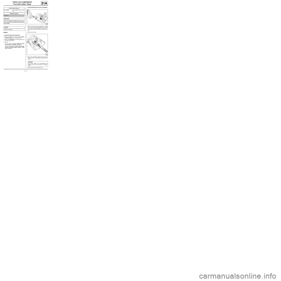
aRemove the piston using compressed air, making
sure to insert a wooden block between the calliper
and the piston to avoid damaging it. Any trace of im-
pact on the end panel will render the piston unfit for
use.
aRemove the dust seal.
aRemove the rectangular section seal from the calli-
per groove with a round edged spring blade (feeler
gauge).
aClean the parts using methylated spirit. Special tooling required
Fre. 1190-01Brake calliper piston return
tool.
Equipment required
pedal press
IMPORTANT
Consult the safety and cleanliness advice and oper-
ation recommendations before carrying out any
repair (see Front axle components: Precautions
for the repair) .
WARNING
Prepare for the flow of fluid, and protect the sur-
rounding components.
81546
81545
WARNING
The whole calliper must systematically be
replaced if there are any scratches in the calliper
bore.
Page 57 of 281
31A-14
FRONT AXLE COMPONENTS
Front brake calliper mounting: Removal - Refitting
EQ UIPMENT LEVEL EA0 or EQUIPMENT LEVEL EA1 or EQUIPMENT LEVEL EA3 or EQUIPMENT LEVEL EA5
or EQUIPMENT LEVEL EAG or EQUIPMENT LEVEL EZ2 or EQUIPMENT LEVEL EZ4
31A
REMOVAL
I - REMOVAL PREPARATION OPERATION
aPosition the vehicle on a two-post lift (see Vehicle:
Towing and lifting) (02A, Lifting equipment).
aRemove:
-the front wheel (see 35A, Wheels and tyres,
Wheel: Removal - Refitting, page 35A-1) ,
-the front brake pads (see 31A, Front axle compo-
nents, Front brake pads: Removal - Refitting,
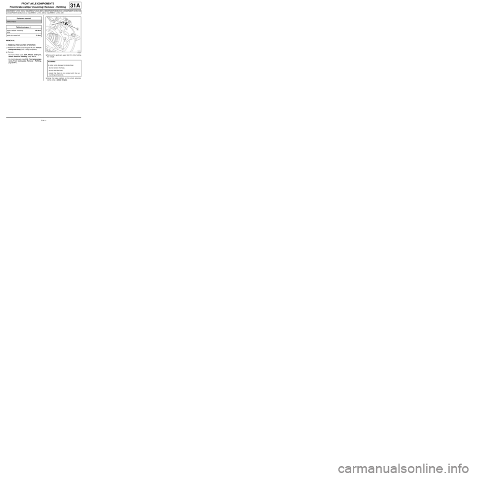
page 31A-1) .aRemove the guide pin upper bolt (1) while holding
the nut (2) .
aHang the brake calliper on the shock absorber
spring using a safety strap(s). Equipment required
safety strap(s)
Tightening torquesm
brake calliper mounting
bolts100 N.m
guide pin upper bolt29 N.m
119218
WARNING
In order not to damage the brake hose:
-do not tension the hose,
-do not twist the hose,
-check that there is no contact with the sur-
rounding components.