tow RENAULT TWINGO 2009 2.G Chasiss Service Manual
[x] Cancel search | Manufacturer: RENAULT, Model Year: 2009, Model line: TWINGO, Model: RENAULT TWINGO 2009 2.GPages: 281
Page 132 of 281
33A-34
REAR AXLE COMPONENTS
Rear stub axle carrier: Removal - Refitting
EQ UIPMENT LEVEL SPORT
33A
REMOVAL
I - REMOVAL PREPARATION OPERATION
aPosition the vehicle on a two-post lift (see Vehicle:
Towing and lifting) (02A, Lifting equipment).
aRemove the rear wheel (see 35A, Wheels and ty-
res, Wheel: Removal - Refitting, page 35A-1) .aUnclip the parking brake cable from the calliper at
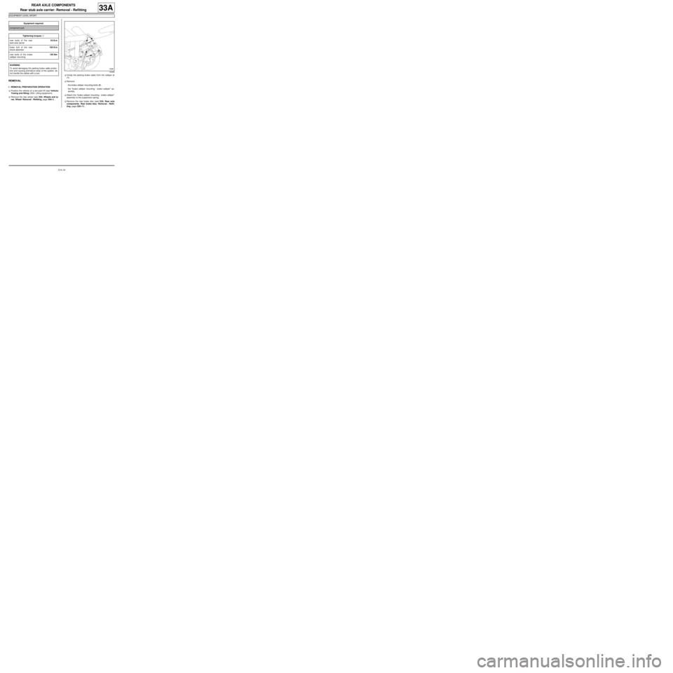
(1) .
aRemove:
-the brake calliper mounting bolts (2) ,
-the "brake calliper mounting - brake calliper" as-
sembly.
aAttach the "brake calliper mounting - brake calliper"
assembly to the suspension spring.
aRemove the rear brake disc (see 33A, Rear axle
components, Rear brake disc: Removal - Refit-
ting, page 33A-11) . Equipment required
component jack
Tightening torquesm
new bolts of the rear
stub axle carrier53 N.m
lower bolt of the rear
shock absorber105 N.m
new bolts of the brake
calliper mounting105 Nm
WARNING
To avoid damaging the parking brake cable protec-
tors and causing premature wear of the system, do
not handle the cables with a tool.
132468
Page 135 of 281
33A-37
REAR AXLE COMPONENTS
Complete rear axle system: Removal - Refitting
33A
REMOVAL
I - REMOVAL PREPARATION OPERATION
aPosition the vehicle on a two-post lift ( (see Vehicle:
Towing and lifting) ).
aRelease the parking brake.
aFit the pedal press on the brake pedal to limit the
amount of brake fluid running out.
aRemove the rear wheels (see 35A, Wheels and ty-
res, Wheel: Removal - Refitting, page 35A-1) .II - OPERATION FOR REMOVAL OF PART
CONCERNED
1 - Removal
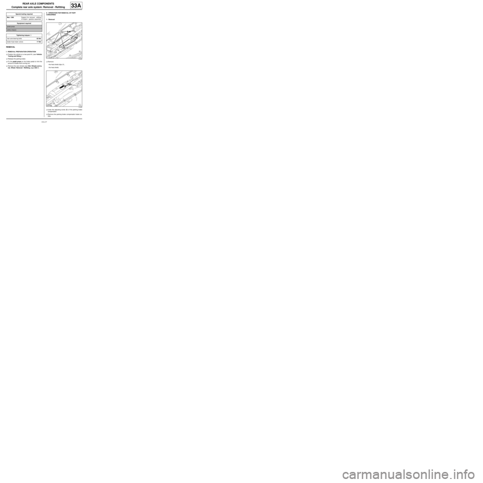
aRemove:
-the heat shield clips (1) ,
-the heat shield.
aUndo the adjusting screw (2) of the parking brake
compensator.
aRemove the parking brake compensator brake ca-
bles. Special tooling required
Mot. 1390Suppor t for removal - refitting
of engine - gearbox assembly
Equipment required
pedal press
safety strap(s)
Tightening torquesm
rear axle bearing bolts62 Nm
brake hose lower unions17 Nm
119435
119436
Page 141 of 281
35A-1
WHEELS AND TYRES
Wheel: Removal - Refitting
35A
The removal - refitting procedure is the same for all
wheels.
REMOVAL
I - REMOVAL PREPARATION OPERATION
aPosition the vehicle on a two-post lift (see Vehicle:
Towing and lifting) (02A, Lifting equipment).
aRelease the parking brake.
aRemove the trim.
aPosition the wheel so that the valve is at the top.
aMark the position of the wheel on the hub.
II - OPERATION FOR REMOVAL OF PART
CONCERNED
aLoosen the wheel bolts with the wheel on the
ground.
aRaise the lift.
aRemove:
-the wheel bolts,
-the wheel.
If the wheel cannot be removed after the bolt has
been undone:
aPosition all the wheel bolts.
aTighten the wheel bolts to bring all the bolt heads
into contact with the wheel.
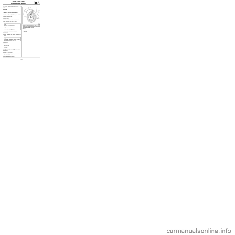
aUndo the wheel bolts by one turn.aStrike around the edge of the tyre walls (1) several
times using a mallet on the inner and outer surfaces
of the wheel to detach the wheel.
aRemove:
-the wheel bolts,
-the wheel. Note:
This mark is required in order to:
-Note the original position of the wheel on the
hub,
-perform the balancing operation.
Note:
Use sockets with protective sheaths in order to
avoid scratching the alloy wheel rims.
100682
Page 144 of 281
35A-4
WHEELS AND TYRES
Wheel: Balancing
35A
I - PREREQUISITES FOR WHEEL BALANCING
aWheel balancing is a measurement operation.
Several conditions must be met to achieve a reliable
result in a single operation.
The wheel balancer must be installed in accordance
with the manufacturer's instructions.
It is essential to calibrate the balancer according to
the frequency recommended by the manufacturer.
Do not grease the threaded shaft.
Check the condition of the supports, centring com-
ponents and mountings.
Replace any faulty parts (see manufacturer's in-
structions).
The wheel and the wheel balancer must be clean.
Driver's perception
aIf the wheels are not correctly balanced this causes
the steering wheel and/or the vehicle floor to vibrate.
These vibrations appear between 54 mph (90 km/h)
and 90 mph (150 km/h).
II - BALANCING PREPARATION OPERATION
aAdjust the tyre pressure (see 35A, Wheels and ty-
res, Tyre pressure: Identification, page 35A-10) .
aAlways carry out a road test for a minimum distance
of 1 mile (2 km) before balancing the wheels, in or-
der to remove any flat spots on the tread caused by
the vehicle being immobilised.
aActions to be carried out immediately after the test
drive:
-Position the vehicle on a two-post vehicle lift (see
Vehicle: Towing and lifting) ,
-raise the vehicle,
-leave the four wheels hanging free,
-release the parking brake.a
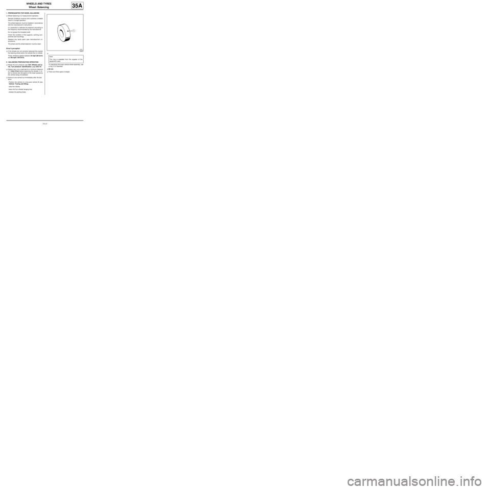
To reproduce the exact vehicle wheel assembly, use
a ring (1) of diameter:
a60 mm
aThere are three types of weight:
105870
Note:
The ring is available from the supplier of the
equipment used.
Page 148 of 281
35A-8
WHEELS AND TYRES
Tyres: Removal - Refitting
35A
REMOVAL
I - REMOVAL PREPARATION OPERATION
aPosition the vehicle on a two-post lift (see Vehicle:
Towing and lifting) (02A, Lifting equipment).
aRemove:
-the wheel in question (see 35A, Wheels and tyres,
Wheel: Removal - Refitting, page 35A-1) ,
-the balance weights,
-the valve mechanism.
II - OPERATION FOR REMOVAL OF PART
CONCERNED
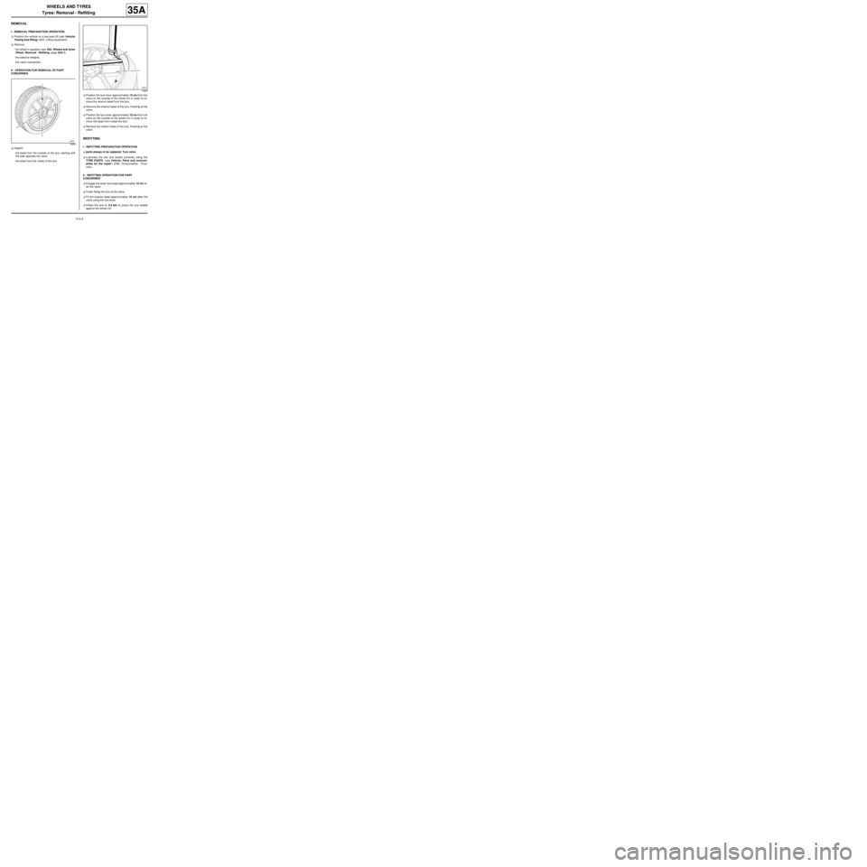
aDetach:
-the bead from the outside of the tyre, starting with
the side opposite the valve,
-the bead from the inside of the tyre.aPosition the tyre lever approximately 15 cm from the
valve on the outside of the wheel rim in order to re-
move the exterior bead from the tyre.
aRemove the exterior bead of the tyre, finishing at the
valve.
aPosition the tyre lever approximately 15 cm from the
valve on the outside of the wheel rim in order to re-
move the bead from inside the tyre.
aRemove the interior bead of the tyre, finishing at the
valve.
REFITTING
I - REFITTING PREPARATION OPERATION
aparts always to be replaced: Tyre valve
aLubricate the two tyre beads correctly using the
TYRE PASTE (see Vehicle: Parts and consum-
ables for the repair) (04B, Consumables - Prod-
ucts).
II - REFITTING OPERATION FOR PART
CONCERNED
aEngage the lower tyre bead approximately 15 cm af-
ter the valve.
aFinish fitting the tyre at the valve.
aFit the exterior bead approximately 15 cm after the
valve using the tyre lever.
aInflate the tyre to 3.5 bar to press the tyre beads
against the wheel rim.
18884
18885
Page 152 of 281
36A-1
STEERING ASSEMBLY
Steering box: Removal - Refitting
36A
REMOVAL
I - REMOVAL PREPARATION OPERATION
aPosition the vehicle on a two-post lift ( (see Vehicle:
Towing and lifting) ).
aRemove:
-the front wheels (see 35A, Wheels and tyres,
Wheel: Removal - Refitting, page 35A-1) ,
-the front wheel arch liners (see Front wheel arch
liner: Removal - Refitting) (55A, Exterior protec-
tion),
-the « subframe - front driveshaft lower arm - power-
assisted steering box - front anti-roll bar » assem-
bly (see 31A, Front axle components, Front axle
subframe: Removal - Refitting, page 31A-43) .
II - OPERATION FOR REMOVAL OF PART
CONCERNED
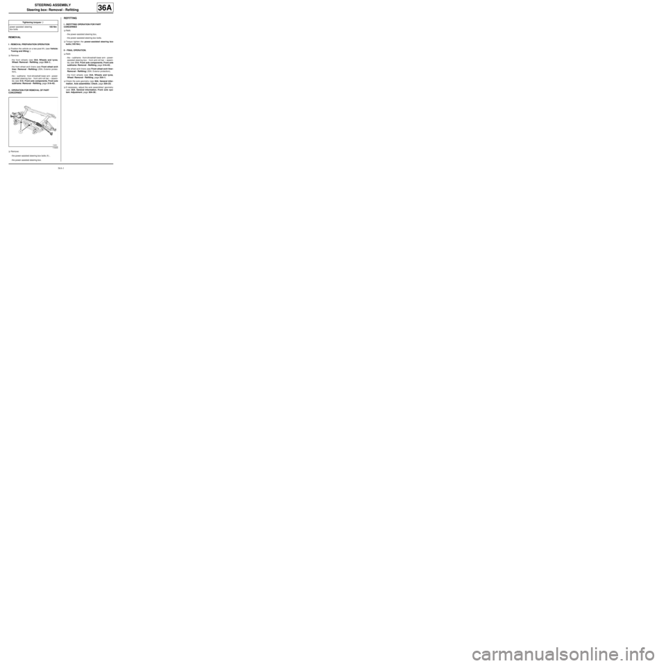
aRemove:
-the power-assisted steering box bolts (1) ,
-the power-assisted steering box.
REFITTING
I - REFITTING OPERATION FOR PART
CONCERNED
aRefit:
-the power-assisted steering box,
-the power-assisted steering box bolts.
aTorque tighten the power-assisted steering box
bolts (105 Nm).
II - FINAL OPERATION.
aRefit:
-the « subframe - front driveshaft lower arm - power-
assisted steering box - front anti-roll bar » assem-
bly (see 31A, Front axle components, Front axle
subframe: Removal - Refitting, page 31A-43) ,
-the wheel arch liners (see Front wheel arch liner:
Removal - Refitting) (55A, Exterior protection),
-the front wheels (see 35A, Wheels and tyres,
Wheel: Removal - Refitting, page 35A-1) .
aCheck the axle geometry (see 30A, General infor-
mation, Axle assemblies: Check, page 30A-23) .
aIf necessary, adjust the axle assemblies' geometry
(see 30A, General information, Front axle sys-
tem: Adjustment, page 30A-36) . Tightening torquesm
power-assisted steering
box bolts105 Nm
119405
Page 153 of 281
36A-2
STEERING ASSEMBLY
Track rod: Removal - Refitting
36A
REMOVAL
I - REMOVAL PREPARATION OPERATION
aPosition the vehicle on a two-post lift (see Vehicle:
Towing and lifting) (02A, Lifting equipment).
aRemove the front wheel (see 35A, Wheels and ty-
res, Wheel: Removal - Refitting, page 35A-1) .
II - OPERATION FOR REMOVAL OF PART
CONCERNED
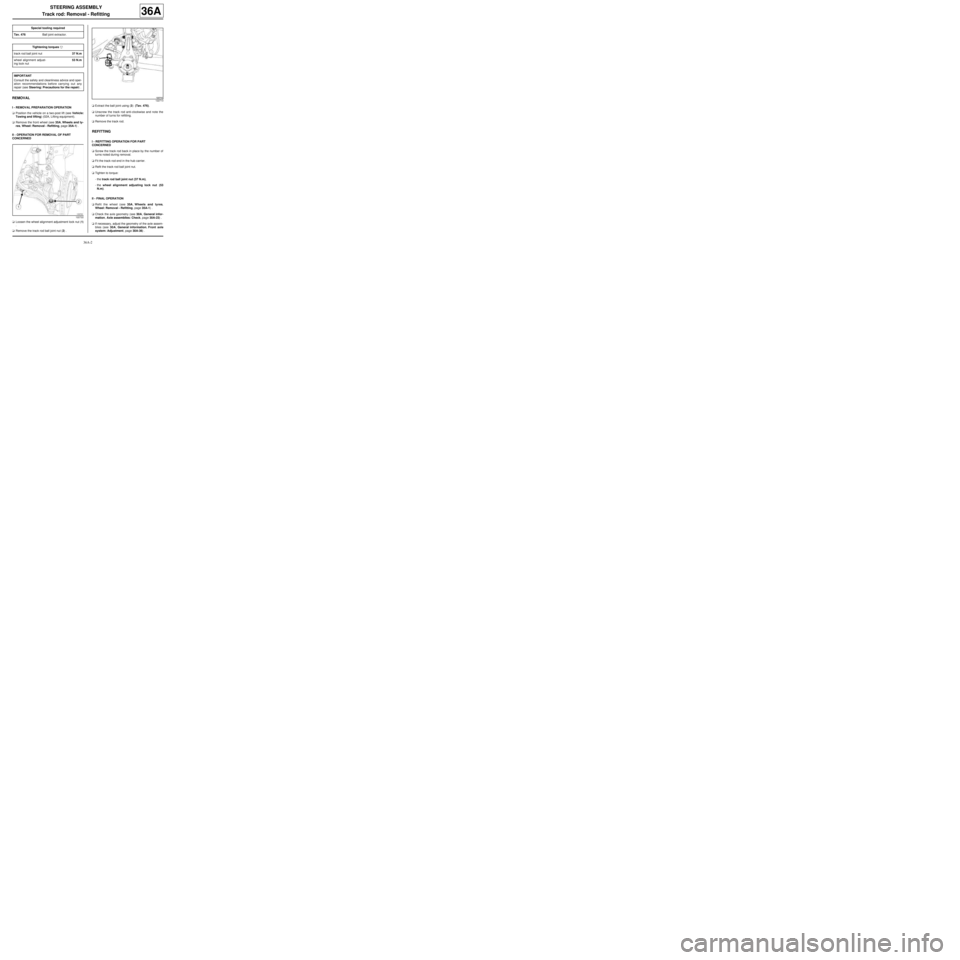
aLoosen the wheel alignment adjustment lock nut (1)
.
aRemove the track rod ball joint nut (2) .aExtract the ball joint using (3) (Tav. 476).
aUnscrew the track rod anti-clockwise and note the
number of turns for refitting.
aRemove the track rod.
REFITTING
I - REFITTING OPERATION FOR PART
CONCERNED
aScrew the track rod back in place by the number of
turns noted during removal.
aFit the track rod end in the hub carrier.
aRefit the track rod ball joint nut.
aTighten to torque:
-the track rod ball joint nut (37 N.m),
-the wheel alignment adjusting lock nut (53
N.m).
II - FINAL OPERATION
aRefit the wheel (see 35A, Wheels and tyres,
Wheel: Removal - Refitting, page 35A-1) .
aCheck the axle geometry (see 30A, General infor-
mation, Axle assemblies: Check, page 30A-23) .
aIf necessary, adjust the geometry of the axle assem-
blies (see 30A, General information, Front axle
system: Adjustment, page 30A-36) . Special tooling required
Tav. 476Ball joint extractor.
Tightening torquesm
track rod ball joint nut37 N.m
wheel alignment adjust-
ing lock nut53 N.m
IMPORTANT
Consult the safety and cleanliness advice and oper-
ation recommendations before carrying out any
repair (see Steering: Precautions for the repair) .
122722
122713
Page 155 of 281
36A-4
STEERING ASSEMBLY
Axial ball joint linkage: Removal - Refitting
36A
REMOVAL
I - REMOVAL PREPARATION OPERATION
aPosition the vehicle on a two-post lift ( (see Vehicle:
Towing and lifting) ).
a
aApply the before repair procedure using the dia-
gnostic tool:
-connect the diagnostic tool,
-select the airbag computer,
-go to repair mode,
-apply the "before repair procedure".
aRemove:
-the front wheel on the side in question (see 35A,
Wheels and tyres, Wheel: Removal - Refitting,
page 35A-1) ,
-the track rod (see 36A, Steering assembly, Track
rod: Removal - Refitting, page 36A-2) ,
-the steering box gaiter (see 36A, Steering assem-
bly, Steering box gaiter: Removal - Refitting,
page 36A-16) .
II - OPERATION FOR REMOVAL OF PART
CONCERNED
aLock the wheels to disengage the rod teeth on the
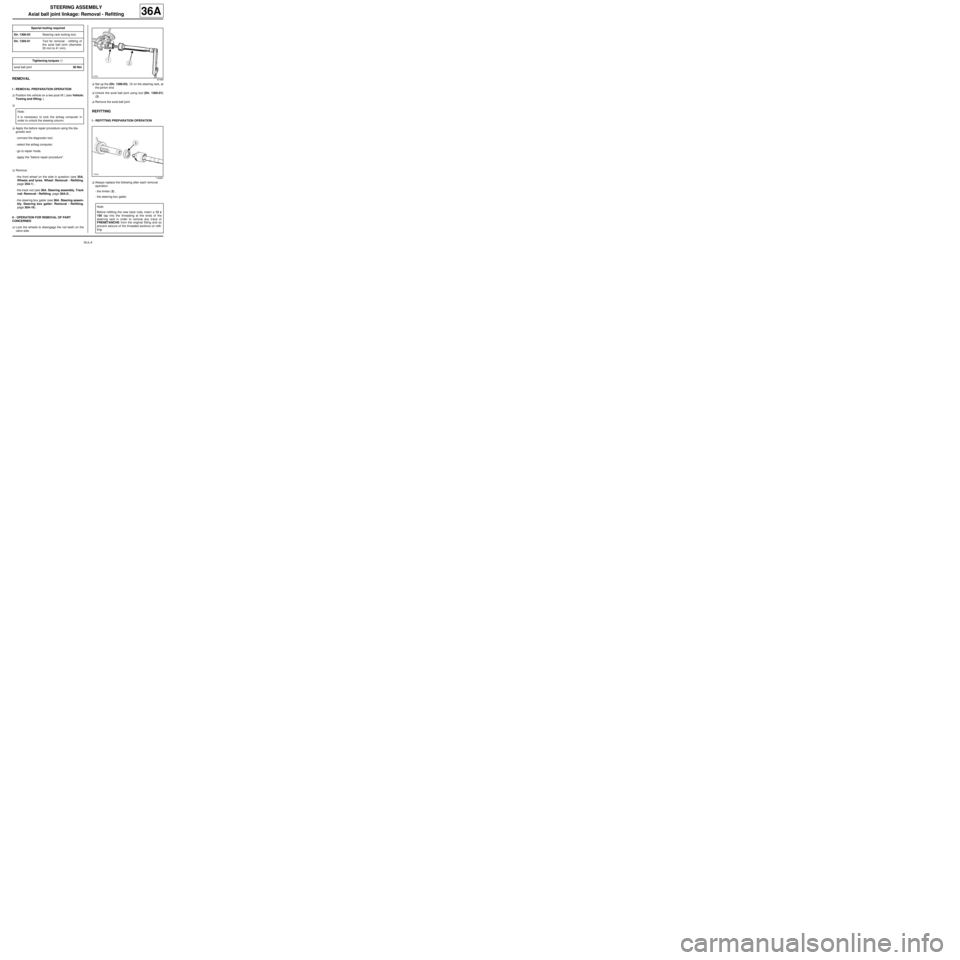
valve side.aSet up the (Dir. 1306-03) (1) on the steering rack, at
the pinion end.
aUnlock the axial ball joint using tool (Dir. 1305-01)
(2) .
aRemove the axial ball joint.
REFITTING
I - REFITTING PREPARATION OPERATION
aAlways replace the following after each removal
operation:
-the limiter (3) ,
-the steering box gaiter. Special tooling required
Dir. 1306-03Steering r ack locking tool.
Dir. 1305-01Tool for removal - refitting of
the axial ball joint (diameter
35 mm to 41 mm).
Tightening torquesm
axial ball joint50 Nm
Note:
It is necessary to lock the airbag computer in
order to unlock the steering column.
97469
116991
Note:
Before refitting the new track rods, inser t a 12 x
100 tap into the threading at the ends of the
steer ing rack in order to remove any trace of
FRENETANCHE from the original fitting and so
pre vent seizure of the threaded sections on refit-
ting.
Page 167 of 281
36A-16
STEERING ASSEMBLY
Steering box gaiter: Removal - Refitting
36A
REMOVAL
I - REMOVAL PREPARATION OPERATION
aPosition the vehicle on a two-post lift (see Vehicle:
Towing and lifting) (02A, Lifting equipment).
aRemove:
-the front wheel (see 35A, Wheels and tyres,
Wheel: Removal - Refitting, page 35A-1) ,
-the track rod, (see 36A, Steering assembly,
Track rod: Removal - Refitting, page 36A-2)
-the wheel alignment adjusting lock nut.
II - OPERATION FOR REMOVAL OF PART
CONCERNED
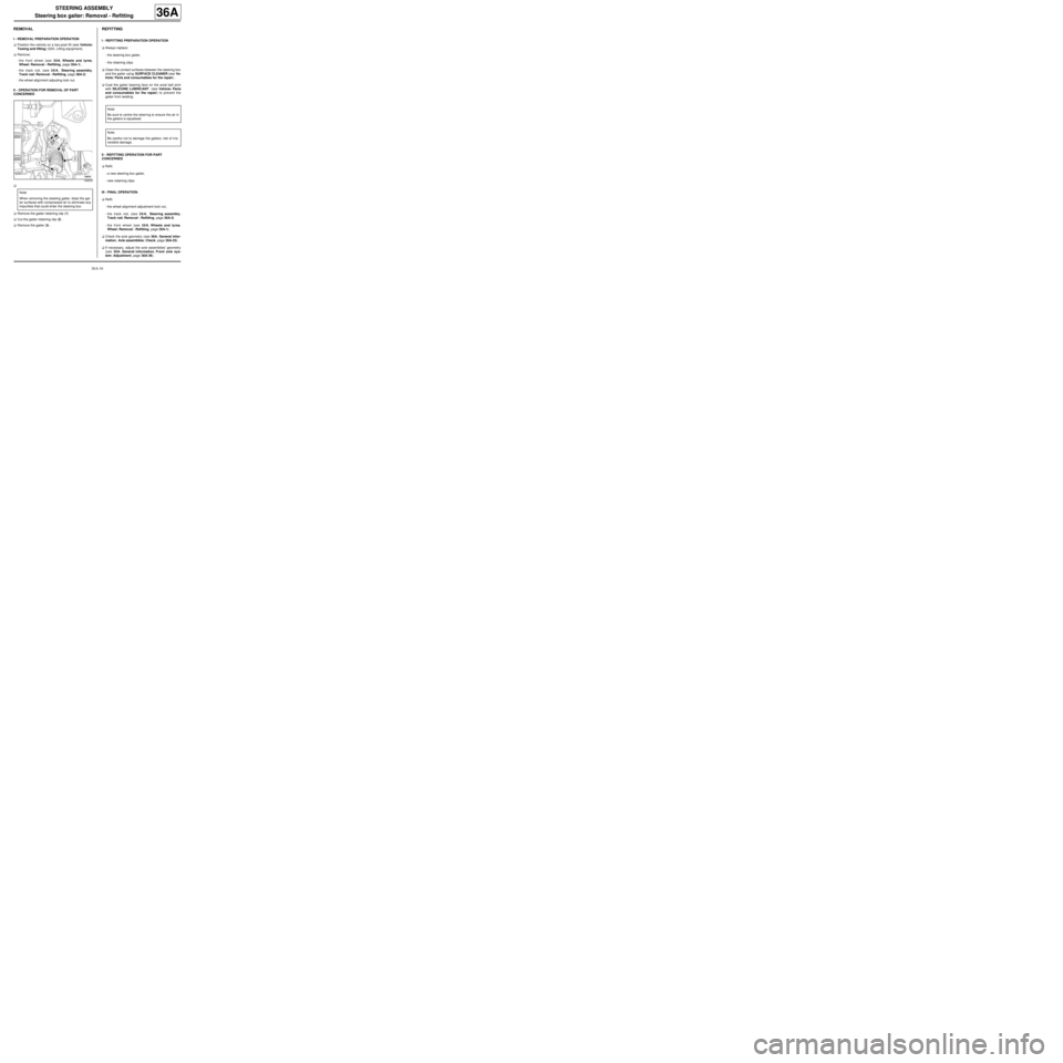
a
aRemove the gaiter retaining clip (1)
aCut the gaiter retaining clip (2) .
aRemove the gaiter (3) .
REFITTING
I - REFITTING PREPARATION OPERATION
aAlways replace:
-the steering box gaiter,
-the retaining clips.
aClean the contact surfaces between the steering box
and the gaiter using SURFACE CLEANER (see Ve-
hicle: Parts and consumables for the repair) .
aCoat the gaiter bearing face on the axial ball joint
with SILICONE LUBRICANT (see Vehicle: Parts
and consumables for the repair) to prevent the
gaiter from twisting.
II - REFITTING OPERATION FOR PART
CONCERNED
aRefit:
-a new steering box gaiter,
-new retaining clips.
III - FINAL OPERATION.
aRefit:
-the wheel alignment adjustment lock nut,
-the track rod, (see 36A, Steering assembly,
Track rod: Removal - Refitting, page 36A-2)
-the front wheel (see 35A, Wheels and tyres,
Wheel: Removal - Refitting, page 35A-1) .
aCheck the axle geometry (see 30A, General infor-
mation, Axle assemblies: Check, page 30A-23) .
aIf necessary, adjust the axle assemblies' geometry
(see 30A, General information, Front axle sys-
tem: Adjustment, page 30A-36) .
105678
Note:
When removing the steering gaiter, blast the gai-
ter surfaces with compressed air to eliminate any
impurities that could enter the steering box.
Note:
Be sure to centre the steer ing to ensure the air in
the gaiters is equalised.
Note:
Be careful not to damage the gaiters: risk of irre-
versible damage.
Page 168 of 281
36A-17
STEERING ASSEMBLY
Bulkhead seal: Removal - Refitting
36A
REMOVAL
I - REMOVAL PREPARATION OPERATION
aPosition the vehicle on a two-post lift ( (see Vehicle:
Towing and lifting) ).
aRemove:
-the front wheels (see 35A, Wheels and tyres,
Wheel: Removal - Refitting, page 35A-1) ,
-the front wheel arch liners ( (see Front wheel arch
liner: Removal - Refitting) ),
-the « subframe - front driveshaft lower arm - power-
assisted steering box - front anti-roll bar » assem-
bly (see 31A, Front axle components, Front axle
subframe: Removal - Refitting, page 31A-43) .
II - OPERATION FOR REMOVAL OF PART
CONCERNED
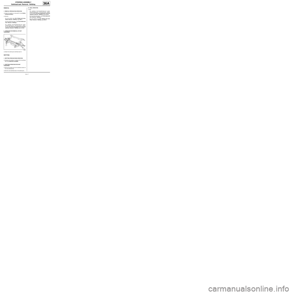
aDetach the steering box bulkhead seal (1) .
REFITTING
I - REFITTING PREPARATIONS OPERATION
aDegrease the surface in contact with the bulkhead
seal using SURFACE CLEANER.
II - REFITTING OPERATION FOR PART
CONCERNED
aRemove the safety film from the adhesive section of
the new bulkhead seal.
aBond the new bulkhead seal on the steering box.III - FINAL OPERATION.
aRefit:
-the « subframe - front driveshaft lower arm - power-
assisted steering box - front anti-roll bar » assem-
bly (see 31A, Front axle components, Front axle
subframe: Removal - Refitting, page 31A-43) ,
-the front wheel arch liners ( (see Front wheel arch
liner: Removal - Refitting) ),
-the front wheels (see 35A, Wheels and tyres,
Wheel: Removal - Refitting, page 35A-1) .
119653