tow RENAULT TWINGO 2009 2.G Chasiss Owner's Manual
[x] Cancel search | Manufacturer: RENAULT, Model Year: 2009, Model line: TWINGO, Model: RENAULT TWINGO 2009 2.GPages: 281
Page 86 of 281
31A-43
FRONT AXLE COMPONENTS
Front axle subframe: Removal - Refitting
31A
REMOVAL
I - REMOVAL PREPARATION OPERATION
aPosition the vehicle on a two-post lift (see Vehicle:
Towing and lifting) (02A, Lifting equipment).
aRemove:
-the front wheels (see 35A, Wheels and tyres,
Wheel: Removal - Refitting, page 35A-1) ,
-the front wheel arch liners (see Front wheel arch
liner: Removal - Refitting) (55A, Exterior protec-
tion).II - OPERATION FOR REMOVAL OF PART
CONCERNED
aRemove the universal joint cover (1) (do not keep).
aSet the wheels straight ahead.
aFit a flywheel immobiliser.
aRemove the bolt (2) from the universal joint (do not
keep).
aTilt the universal joint on the steering box to detach it
from the pinion. Special tooling required
Tav. 476Ball joint extractor.
Mot. 1390Suppor t for removal - refitting
of engine - gearbox assembly
Equipment required
flywheel immobiliser
Tightening torquesm
rear subframe bolts105 Nm
front subframe bolts62 Nm
front end cross member
bolts21 Nm
acoustic tie-rod bolts21 Nm
acoustic tie-rod bolts90 Nm
subframe tie-rod bolts21 Nm
subframe tie-rod nuts62 Nm
gear lever arm nut28 Nm
nuts of the lower arm
ball joints62 N.m
bolts of the lower ball
joints62 N.m
nuts of the track rod
ends37 N.m
universal joint bolt24 Nm
119544
Note:
Do not pull the intermediate shaft out.
Page 95 of 281
31A-52
FRONT AXLE COMPONENTS
Front anti-roll bar: Removal - Refitting
EQ UIPMENT LEVEL EA0 or EQUIPMENT LEVEL EA1 or EQUIPMENT LEVEL EA3 or EQUIPMENT LEVEL EA5
or EQUIPMENT LEVEL EAG or EQUIPMENT LEVEL EZ2 or EQUIPMENT LEVEL EZ4
31A
Anti-roll bar specifications:
REMOVAL
I - REMOVAL PREPARATION OPERATION
aPosition the vehicle on a two-post lift (see Vehicle:
Towing and lifting) (02A, Lifting equipment).
aRemove the front axle subframe (see 31A, Front
axle components, Front axle subframe: Removal
- Refitting, page 31A-43) .II - OPERATION FOR REMOVAL OF PART
CONCERNED
aCompress the anti-roll bar rubber mounting bush on
the wheel side using the (Sus. 1413).
aRemove:
-the bolt (1) from the anti-roll bar on the wheel side,
-the rubber mounting bush from the anti-roll bar,
-the anti-roll bar bearing bolts (2) ,
-the anti-roll bar bearings,
-the anti-roll bar,
-the rubber mounting bush from the anti-roll bar
bearing.
REFITTING
REFITTING OPERATION FOR PART CONCERNED
aRefit:
-the anti-roll bar bearing rubber mounting bush,
-the anti-roll bar.
aFit the anti-roll bar bearings into the subframe neck. Special tooling required
Sus. 1413Rubber mounting compres-
sor for fitting the anti-roll bar.
(wheel end).
Sus. 1824Fork for fitting the anti-roll bar
centre bearings.
Tightening torquesm
anti-roll bar bearing
bolts on the subframe35 Nm
anti-roll bar bolt on the
wheel side14 Nm
Engine Ø of the strut in
mm
D7F 25
D4F, K9K 26
119406
Page 97 of 281
31A-54
FRONT AXLE COMPONENTS
Front anti-roll bar: Removal - Refitting
EQ UIPMENT LEVEL SPORT
31A
Anti-roll bar specifications:
REMOVAL
I - REMOVAL PREPARATION OPERATION
aPosition the vehicle on a two-post lift (see Vehicle:
Towing and lifting) (02A, Lifting equipment).
aRemove:
-the front wheels (see 35A, Wheels and tyres,
Wheel: Removal - Refitting, page 35A-1) ,
-the wheel arch liners (see Front wheel arch liner:
Removal - Refitting) (55A, Exterior protection),
-the front axle subframe (see 31A, Front axle com-
ponents, Front axle subframe: Removal - Refit-
ting, page 31A-43) .II - OPERATION FOR REMOVAL OF PART
CONCERNED
aRemove:
-the nuts (1) of the anti-roll bar tie rods,
-the anti-roll bar tie rods from the anti-roll bar.
aRemove:
-the anti-roll bar bearing bolts (2) ,
-the anti-roll bar bearings (3) ,
-the anti-roll bar, Special tooling required
Sus. 1824Fork for fitting the anti-roll bar
centre bearings.
Tightening torquesm
anti-roll bar bearing
bolts35 N.m
Colour∅ of the strut in mm
Brown 21
Blue 20132461
132457
Page 99 of 281
33A-1
REAR AXLE COMPONENTS
Rear brake pads: Removal - Refitting
EQ UIPMENT LEVEL SPORT
33A
When replacing brake pads, be sure to replace the
pads on the opposite side.
REMOVAL
I - REMOVAL PREPARATION OPERATION
aPosition the vehicle on a two-post lift (see Vehicle:
Towing and lifting) (02A, Lifting equipment).
aRelease the parking brake.
aRemove the rear wheels (see 35A, Wheels and ty-
res, Wheel: Removal - Refitting, page 35A-1) .II - OPERATION FOR REMOVAL OF PART
CONCERNED
aUnclip the parking brake cable from the brake calli-
per at (1) .
aMove aside the parking brake cable.
aRemove the lower bolt (2) of the brake calliper guide
pin.
aTilt the brake calliper over.
aRemove the brake pads (3) from the brake calliper
mounting. Special tooling required
Fre. 1190-01Brake calliper piston return
tool.
Tightening torquesm
new lower bolts of the
calliper guide pins35 N.m
WARNING
To avoid damaging the parking brake cable protec-
tors and causing premature wear of the system, do
not handle the cables with a tool.
132468
132466
Page 102 of 281
33A-4
REAR AXLE COMPONENTS
Rear brake hose: Removal - Refitting
33A
REMOVAL
I - REMOVAL PREPARATION OPERATION
aPosition the vehicle on a two-post lift ( (see Vehicle:
Towing and lifting) ).
aFit the pedal press to the brake pedal to limit the
outflow of brake fluid.
II - OPERATION FOR REMOVAL OF PART
CONCERNED
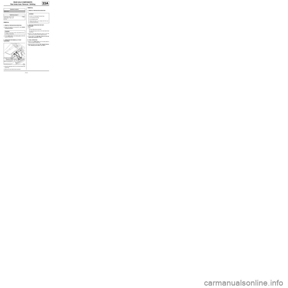
aUndo the rigid pipe unions (1) on the rear brake hose
concerned.
aRemove the rear brake hose concerned.
REMOVAL
I - REMOVAL PREPARATION OPERATION
a
II - REFITTING OPERATION FOR PART
CONCERNED
aRefit:
-the rear brake hose concerned,
-the rigid brake pipe unions on the rear brake hose
concerned.
aScrew on the rigid brake pipe unions on the rear
brake hose concerned without tightening them.
aTorque tighten the rigid pipe unions on the rear
brake hose concerned ( 17 Nm).
III - FINAL OPERATION.
aRemove the pedal press from the brake pedal to
limit the outflow of brake fluid.
aBleed the brake circuit (see 30A, General informa-
tion, Braking circuit: Bleed, page 30A-4) . Equipment requiredpedal press
Tightening torquesm
rigid pipe unions on the
rear brake hose con-
cerned17 Nm
WARNING
Prepare for the flow of fluid, and protect the sur-
rounding components.
119339
WARNING
In order to not damage the brake hose:
-do not tension the hose,
-do not twist the hose,
-check that there is no contact with the sur-
rounding components.
Page 103 of 281
33A-5
REAR AXLE COMPONENTS
Rear brake hose: Removal - Refitting
EQ UIPMENT LEVEL SPORT
33A
REMOVAL
I - REMOVAL PREPARATION OPERATION
aPosition the vehicle on a two-post lift (see Vehicle:
Towing and lifting) (02A, Lifting equipment).
aPosition a pedal press on the brake pedal to limit
the outflow of brake fluid.II - OPERATION FOR REMOVAL OF PART
CONCERNED
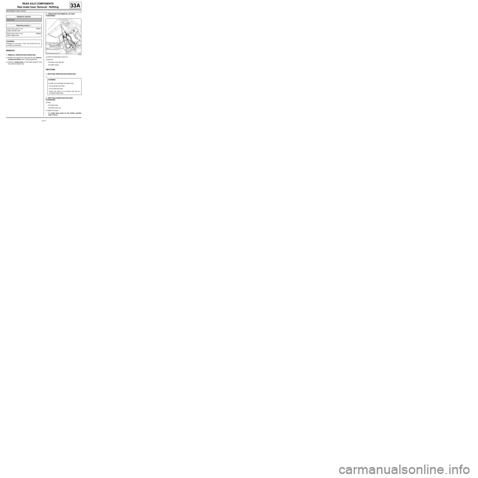
aUndo the brake pipe unions (1) .
aRemove:
-the brake hose clips (2) ,
-the brake hoses.
REFITTING
I - REFITTING PREPARATION OPERATION
a
II - REFITTING OPERATION FOR PART
CONCERNED
aRefit:
-the brake hose,
-the brake hose clip.
aTighten to torque:
-the brake hose union on the master cylinder
side (13 N.m), Equipment required
pedal press
Tightening torquesm
brake hose union on the
master cylinder side13 N.m
brake hose union on the
brake calliper side13 N.m
WARNING
Prepare for the flow of fluid, and protect the sur-
rounding components.
119339
WARNING
In order not to damage the brake hose:
-do not tension the hose,
-do not twist the hose,
-check that there is no contact with the sur-
rounding components.
Page 105 of 281

33A-7
REAR AXLE COMPONENTS
Rear brake calliper: Removal - Refitting
EQ UIPMENT LEVEL SPORT
33A
REMOVAL
I - REMOVAL PREPARATION OPERATION
aPosition the vehicle on a two-post lift (see Vehicle:
Towing and lifting) (02A, Lifting equipment).
aRelease the parking brake.
aPosition a pedal press on the brake pedal to limit
the outflow of brake fluid.
aRemove the rear wheel (see 35A, Wheels and ty-
res, Wheel: Removal - Refitting, page 35A-1) .II - OPERATION FOR REMOVAL OF PART
CONCERNED
aUnclip the parking brake cable from the brake calli-
per at (1) .
aMove aside the parking brake cable.
aLoosen the calliper brake pipe union (2) .
aRemove:
-the brake calliper guide pin bolts (3) ,
-the brake calliper from the mounting,
-the union between the brake pipe and the calliper,
-the brake calliper.
REFITTING
I - REFITTING PREPARATION OPERATION
aClean using a wire brush and BRAKE CLEANER
(see Vehicle: Parts and consumables for the re-
pair) (04B, Consumables - Products):
-the calliper supports,
-the callipers.
aAlways replace the brake calliper guide pin bolts. Special tooling required
Fre. 1190-01Brake calliper piston return
tool.
Equipment required
pedal press
Tightening torquesm
new bolts on the brake
calliper guide pins35 N.m
brake pipe union on the
calliper13 N.m
WARNING
To avoid damaging the parking brake cable protec-
tors and causing premature wear of the system, do
not handle the cables with a tool.
132468
Page 107 of 281
33A-9
REAR AXLE COMPONENTS
Rear brake calliper mounting: Removal - Refitting
EQ UIPMENT LEVEL SPORT
33A
REMOVAL
I - REMOVAL PREPARATION OPERATION
aPosition the vehicle on a two-post lift (see Vehicle:
Towing and lifting) (02A, Lifting equipment).
aRelease the parking brake.
aRemove:
-the rear wheel (see 35A, Wheels and tyres,
Wheel: Removal - Refitting, page 35A-1) ,
-the rear brake pads (see 33A, Rear axle compo-
nents, Rear brake pads: Removal - Refitting,
page 33A-1) .aRemove:
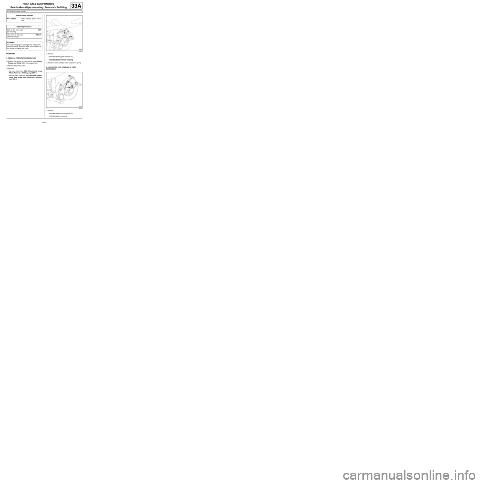
-the brake calliper guide pin bolts (1) ,
-the brake calliper from the mounting.
aAttach the brake calliper to the suspension spring.
II - OPERATION FOR REMOVAL OF PART
CONCERNED
aRemove:
-the brake calliper mounting bolts (2) ,
-the brake calliper mounting. Special tooling required
Fre. 1190-01Brake calliper piston return
tool.
Tightening torquesm
bolts of the brake calli-
per mountingXXX
new bolts of the brake
calliper guide pins105 N.m
WARNING
To avoid damaging the parking brake cable protec-
tors and causing premature wear of the system, do
not handle the cables with a tool.
132468
132465
Page 109 of 281

33A-11
REAR AXLE COMPONENTS
Rear brake disc: Removal - Refitting
EQ UIPMENT LEVEL SPORT
33A
Brake discs cannot be reground. If there is excessive
scoring or wear, they will need to be replaced (see
30A, General information, Brake: Specifications,
page 30A-19) .
REMOVAL
I - REMOVAL PREPARATION OPERATION
aPosition the vehicle on a two-post lift (see Vehicle:
Towing and lifting) (02A, Lifting equipment).
aRemove:
-the rear wheels (see 35A, Wheels and tyres,
Wheel: Removal - Refitting, page 35A-1) ,
-the rear brake pads (see 33A, Rear axle compo-
nents, Rear brake pads: Removal - Refitting,
page 33A-1) .aRemove:
-the brake calliper mounting bolts (1) ,
-the "brake calliper mounting - brake calliper" as-
sembly.
aAttach the "calliper mounting - brake calliper" to the
shock absorber spring.
II - OPERATION FOR REMOVAL OF PART
CONCERNED
aRemove the hub's nut cover (2) . Equipment required
par ts washer
Tightening torquesm
new hub nut175 N.m
brake calliper mounting
bolts105 N.m
WARNING
To avoid damaging the parking brake cable protec-
tors and causing premature wear of the system, do
not handle the cables with a tool.
132467
132456
Page 111 of 281
33A-13
REAR AXLE COMPONENTS
Rear brake disc: Description
EQ UIPMENT LEVEL SPORT
33A
I - PREPARATION OPERATION FOR CHECK
Position the vehicle on a two-post lift (see Vehicle:
Towing and lifting) (02A, Lifting equipment).
Remove the rear wheel concerned (see 35A, Wheels
and tyres, Wheel: Removal - Refitting, page 35A-1) .
II - CHECKING OPERATION FOR PART
CONCERNED
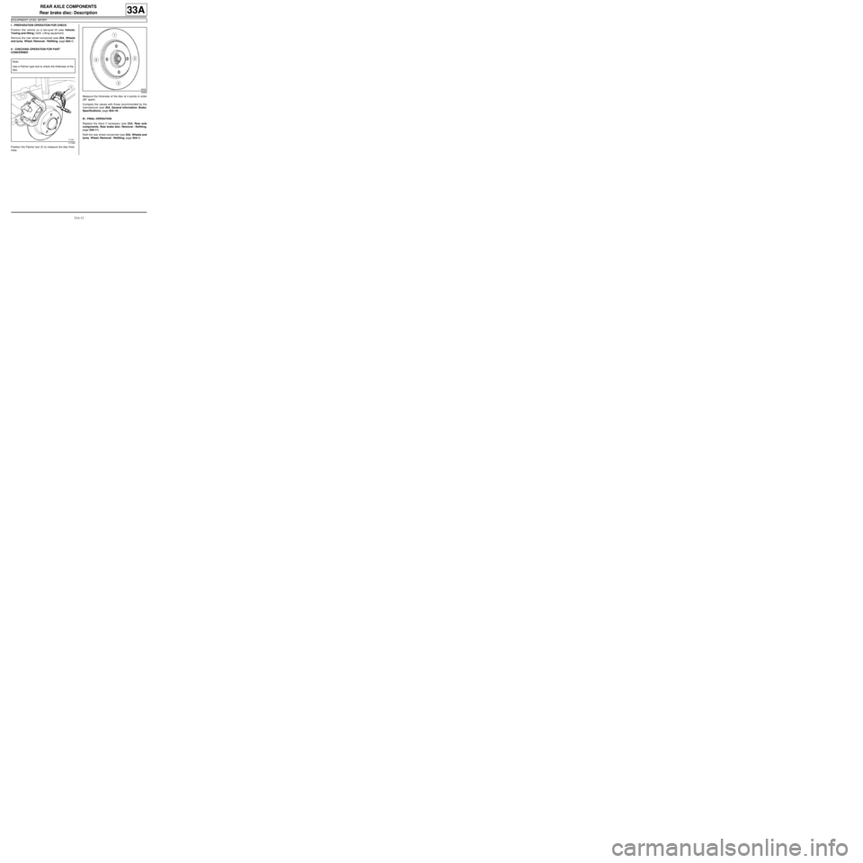
Position the Palmer tool (1) to measure the disc thick-
ness.Measure the thickness of the disc at 4 points in order
(90˚ apart).
Compare the values with those recommended by the
manufacturer (see 30A, General information, Brake:
Specifications, page 30A-19) .
III - FINAL OPERATION
Replace the discs if necessary (see 33A, Rear axle
components, Rear brake disc: Removal - Refitting,
page 33A-11) .
Refit the rear wheel concerned (see 35A, Wheels and
tyres, Wheel: Removal - Refitting, page 35A-1) . Note:
Use a Palmer type tool to check the thickness of the
disc.
117058
99582