warning RENAULT TWINGO 2009 2.G Electrical Equipment - Multiplexing Workshop Manual
[x] Cancel search | Manufacturer: RENAULT, Model Year: 2009, Model line: TWINGO, Model: RENAULT TWINGO 2009 2.GPages: 33, PDF Size: 0.18 MB
Page 17 of 33

88B-17V3 MR-413-X44-88B000$060.mif
88B
MULTIPLEX NETWORK CONFIGURATION
For the
CAN Vehicle network:
The tool displays the UCH and/or Airbag configurations.
The Configuration screen consists of two tabs for displaying and modifying the:
–The first tab, Multiplex network configuration, indicates the multiplex network version and the list of computers
defined as present on the multiplex network.
–The second tab, Configuration of computers which support fault finding, indicates the relevant diagram
number, and the list of computers defined as supporting fault finding with the RENAULT tool.
First repair the computers containing the multiplex network configuration (Airbag and UCH) in order to
display the screen with the multiplex network configuration diagram for the vehicle on which fault finding is
being run.
For the
CAN Multimedia network:
The tool presents the configuration of the A2/A3 display.
The Configuration screen consists of two tabs for displaying and modifying the:
–The first tab, Multiplex network configuration, indicates the multiplex network version and the list of computers
defined as present on the multiplex network.
–The second tab, Configuration of computers which support fault finding, indicates the relevant diagram
number, and the list of computers defined as supporting fault finding with the RENAULT tool.
NOTESThe configuration is entered with the ignition on; apply the forced + after ignition
feed procedure (see Introduction).
It can be run from the multiplex network test results screens.
WARNING: the network version number is 1.
This is the diagram version which changes each time the multiplex network wiring is modified on this vehicle.
WARNING: the network version number is 1.
This is the diagram version which changes each time the multiplex network wiring is modified on this vehicle.
MULTIPLEXING
Fault finding – Configuration
Page 30 of 33

88B-30V3 MR-413-X44-88B000$080.mif
MULTIPLEXING
Fault finding – Fault finding chart88B
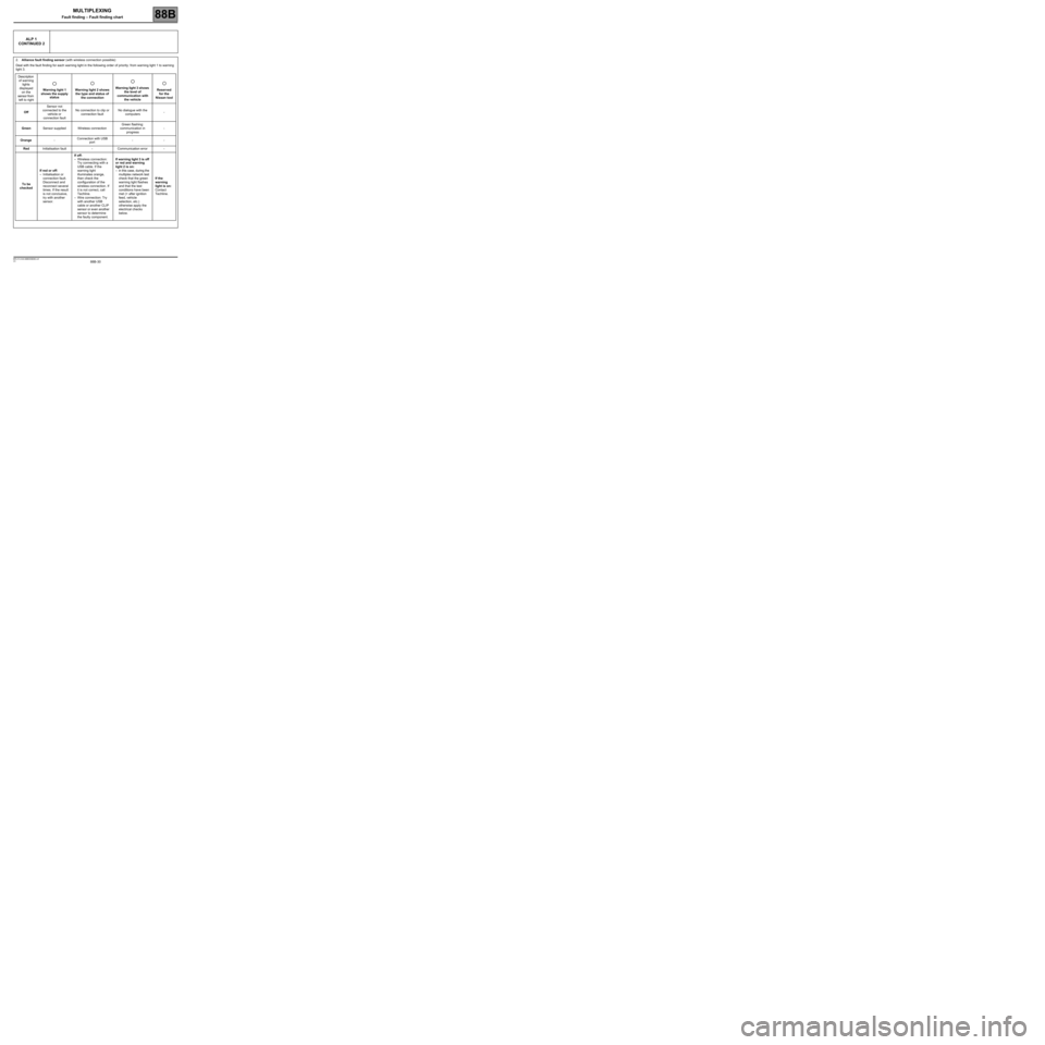
ALP 1
CONTINUED 2
2.Alliance fault finding sensor (with wireless connection possible):
Deal with the fault finding for each warning light in the following order of priority: from warning light 1 to warning
light 3.
Description
of warning
lights
displayed
on the
sensor from
left to rightWarning light 1
shows the supply
statusWarning light 2 shows
the type and status of
the connectionWarning light 3 shows
the level of
communication with
the vehicleReserved
for the
Nissan tool
OffSensor not
connected to the
vehicle or
connection faultNo connection to clip or
connection faultNo dialogue with the
computers-
GreenSensor supplied Wireless connectionGreen flashing:
communication in
progress-
Orange-Connection with USB
port--
RedInitialisation fault - Communication error -
To be
checkedIf red or off:
–Initialisation or
connection fault.
Disconnect and
reconnect several
times. If the result
is not conclusive,
try with another
sensor.If off:
–Wireless connection:
Try connecting with a
USB cable. If the
warning light
illuminates orange,
then check the
configuration of the
wireless connection. If
it is not correct, call
Techline.
–Wire connection: Try
with another USB
cable or another CLIP
sensor or even another
sensor to determine
the faulty component.If warning light 3 is off
or red and warning
light 2 is on:
–in this case, during the
multiplex network test
check that the green
warning light flashes
and that the test
conditions have been
met (+ after ignition
feed, vehicle
selection, etc.)
otherwise apply the
electrical checks
below.If the
warning
light is on:
Contact
Techline.