fault summary table RENAULT TWINGO 2009 2.G Electrical Equipment - Petrol Injection Workshop Manual
[x] Cancel search | Manufacturer: RENAULT, Model Year: 2009, Model line: TWINGO, Model: RENAULT TWINGO 2009 2.GPages: 348
Page 1 of 348
8Electrical equipment
V7 MR-413-X44-17B000$TOC.mif
V7
17B
"The repair procedures given by the manufacturer in this document are based on the
technical specifications current when it was prepared.
The procedures may be modified as a result of changes introduced by the
manufacturer in the production of the various component units and accessories from
which his vehicles are constructed."
V7
All rights reserved by Renault s.a.s.
Edition Anglaise
Copying or translating, in part or in full, of this document or use of the service part
reference numbering system is forbidden without the prior written authority of
Renault s.a.s.
© Renault s.a.s. 2009
PETROL INJECTION
SIM 32 Injection
Program no.: D3
Vdiag No.: 44, 4C, 50 and 54
Fault finding – Introduction 17B - 2
Fault finding – Cleanliness guidelines 17B - 8
Fault finding – System operation 17B - 10
Fault finding – List and location of components 17B - 19
Fault finding – Functional diagram 17B - 21
Fault finding – Features 17B - 22
Fault finding – Role of components 17B - 28
Fault finding – Defect modes 17B - 32
Fault finding – Replacement of components 17B - 35
Fault finding – Configurations 17B - 37
Fault finding – Programming 17B - 39
Fault finding – Fault summary table 17B - 40
Fault finding – Interpretation of faults 17B - 43
Fault finding – Conformity check 17B - 167
Fault finding – Status summary table 17B - 168
Fault finding – Interpretation of statuses 17B - 171
Fault finding – Parameter summary table 17B - 263
Fault finding – Interpretation of parameters 17B - 265
Fault finding – Command summary table 17B - 327
Fault finding – Interpretation of commands 17B - 329
Fault finding – Customer complaints 17B - 339
Fault finding – Fault Finding Chart 17B - 340
Fault finding – Tests 17B - 346
Page 16 of 348
17B-16V7 MR-413-X44-17B000$030.mif
PETROL INJECTION
Fault finding – System operation17B
SIM 32 Injection
Program no.: D3
Vdiag No.: 44, 4C, 50
and 54
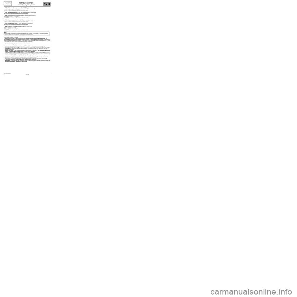
–DF089 Inlet manifold pressure sensor fault 1.DEF: Signal inconsistency.
Or 2. DEF: Open circuit or short circuit.
Or 3. DEF: Non-compliance with emission control standards.
–DF091 Vehicle speed signal in 1.DEF: No multiplex signals or invalid values.
Or 2. DEF: Non-compliance with emission control standards.
–DF001 Coolant temperature sensor circuit in 1.DEF: Signal inconsistency.
Or 2. DEF: Open circuit or short circuit.
Or 3. DEF: Non-compliance with emission control standards.
–DF002 Air temperature circuit in 1. DEF: Open circuit or short circuit.
Or 2. DEF: Non-compliance with emission control standards.
–DF330 Pinking sensor circuit in 1.DEF: Open circuit or short circuit.
Or 2. DEF: Non-compliance with emission control standards.
–DF893 Controlled coolant thermostat circuit in CO: Open circuit.
Or CC.0: Short circuit to earth.
Or CC.1: Short circuit to + 12 volts.
Or 1. DEF: Non-compliance with emission control standards.
Engine torque limitation is activated.
If the fault is directly linked to the controlled thermostat (DF893 Controlled coolant thermostat circuit), the
thermostat is no longer controlled. It operates continuously, either in low temperature mode (instance of short circuit to
earth) or in high temperature mode (instance of open circuit or short circuit to the battery). The engine torque is limited
to limit heating and also to protect the engine by preventing overheating.
c. Functions affected by the presence of a controlled thermostat:
–Coolant temperature: 108˚C nominal, between 70˚C and 90˚C in defect mode or on loaded points.
–Coolant temperature fault finding: the fault finding setting for coolant temperature consistency has been adapted.
–Consumption: The function improves fuel consumption. Consequence: a fault with the function may lead to
inefficient consumption.
–Bleeding the circuit: A new procedure adapted to this innovation is described in MR 392 and 385, Mechanical
systems, CLIO III and MODUS, 19A Cooling, Cooling circuit: Bleeding.
–Coolant temperature display and illumination of the warning light on the instrument panel: During nominal
operation there is no impact as the temperature reference value is taken into account as well as the warning light
illumination thresholds. In the event of malfunction, see the summary table below.
–Fan unit and air conditioning: the fan unit activation threshold and the high temperature air conditioning
deactivation threshold are adapted in accordance with the temperature setpoint.
–Fault finding of controlled thermostat: Electrical fault finding is used. No operational fault finding:
A mechanical fault (such as jamming) will not be detected by the system.
–Performance: In the event of a fault, there is the option to switch the engine to reduced performance mode (see
Description of operation: Operation in defect mode). Note:
If a fault on the coolant temperature sensor is detected, fan assembly 1 is requested to operate permanently,
regardless of the management mode of the engine coolant temperature.
Page 17 of 348
17B-17V7 MR-413-X44-17B000$030.mif
PETROL INJECTION
Fault finding – System operation17B
SIM 32 Injection
Program no.: D3
Vdiag No.: 44, 4C, 50
and 54
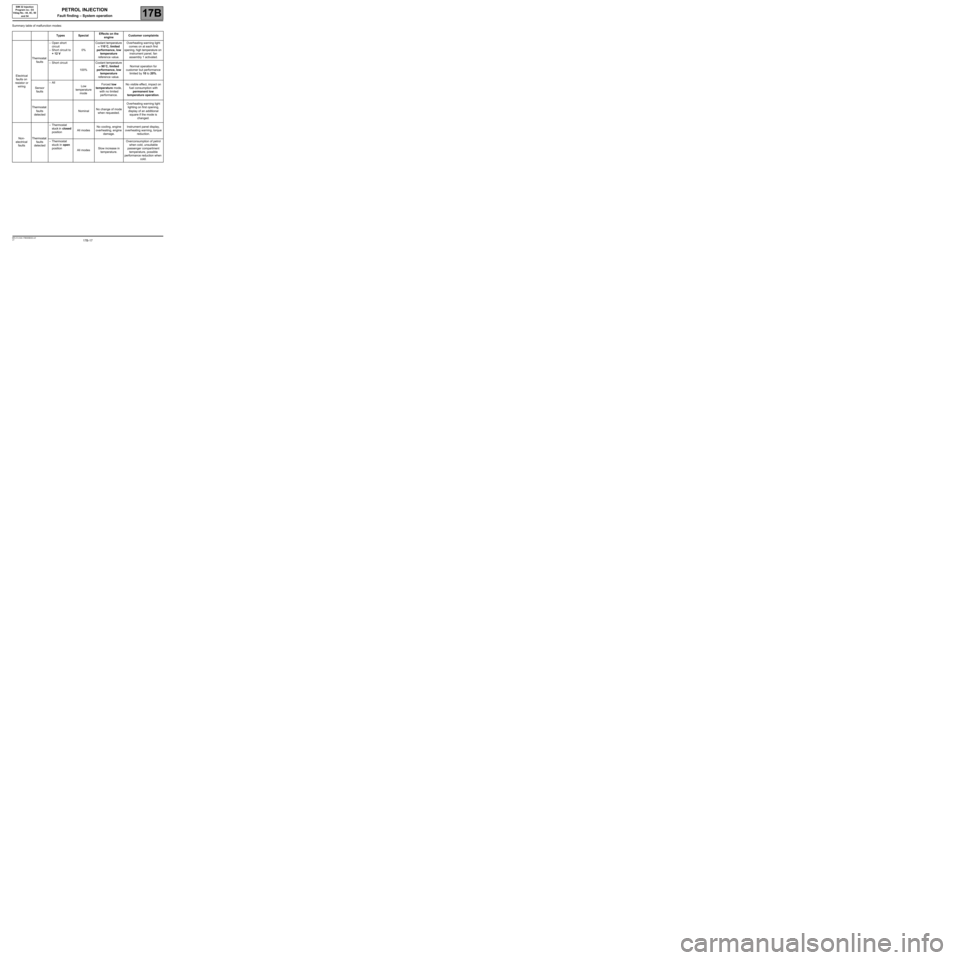
Summary table of malfunction modes:
Types SpecialEffects on the
engineCustomer complaints
Electrical
faults on
resistor or
wiringThermostat
faults–Open short
circuit
–Short circuit to
+ 12 V0%Coolant temperature
≈ 110˚C, limited
performance, low
temperature
reference value.Overheating warning light
comes on at each first
opening, high temperature on
instrument panel, fan
assembly 1 activated.
–Short circuit
100%Coolant temperature
≈ 90˚C, limited
performance, low
temperature
reference value.Normal operation for
customer but performance
limited by 10 to 20%.
Sensor
faults–All
Low
temperature
modeForced low
temperature mode,
with no limited
performance.No visible effect, impact on
fuel consumption with
permanent low
temperature operation.
Thermostat
faults
detectedNominalNo change of mode
when requested.Overheating warning light
lighting on first opening,
display of an additional
square if the mode is
changed.
Non-
electrical
faultsThermostat
faults
detected–Thermostat
stuck in closed
positionAll modesNo cooling, engine
overheating, engine
damage.Instrument panel display,
overheating warning, torque
reduction.
–Thermostat
stuck in open
position
All modesSlow increase in
temperature.Overconsumption of petrol
when cold, unsuitable
passenger compartment
temperature, possible
performance reduction when
cold.
Page 40 of 348
17B-40V7 MR-413-X44-17B000$120.mif
17B
SIM 32 Injection
Program no.: D3
Vdiag No.: 44, 4C, 50
and 54
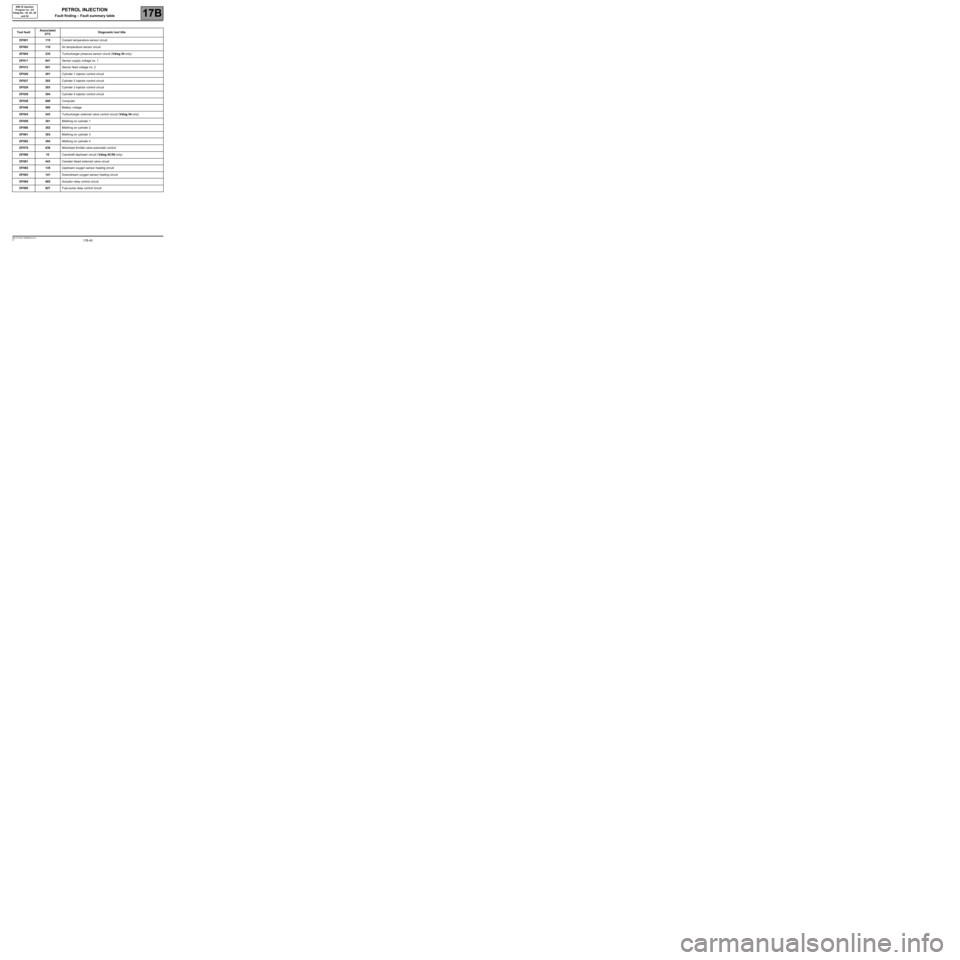
Tool faultAssociated
DTCDiagnostic tool title
DF001115Coolant temperature sensor circuit
DF002110Air temperature sensor circuit
DF004235Turbocharger pressure sensor circuit (Vdiag 54 only)
DF011641Sensor supply voltage no. 1
DF012651Sensor feed voltage no. 2
DF026201Cylinder 1 injector control circuit
DF027202Cylinder 2 injector control circuit
DF028203Cylinder 3 injector control circuit
DF029204Cylinder 4 injector control circuit
DF038606Computer
DF046560Battery voltage
DF054243Turbocharger solenoid valve control circuit (Vdiag 54 only)
DF059301Misfiring on cylinder 1
DF060302Misfiring on cylinder 2
DF061303Misfiring on cylinder 3
DF062304Misfiring on cylinder 4
DF079638Motorised throttle valve automatic control
DF08010Camshaft dephaser circuit (Vdiag 4C/50 only)
DF081443Canister bleed solenoid valve circuit
DF082135Upstream oxygen sensor heating circuit
DF083141Downstream oxygen sensor heating circuit
DF084685Actuator relay control circuit
DF085627Fuel pump relay control circuit
PETROL INJECTION
Fault finding – Fault summary table
Page 41 of 348
17B-41V7 MR-413-X44-17B000$120.mif
PETROL INJECTION
Fault finding – Fault summary table17B
SIM 32 Injection
Program no.: D3
Vdiag No.: 44, 4C, 50
and 54
* TA: Automatic Transmission
* TDB: Instrument panel
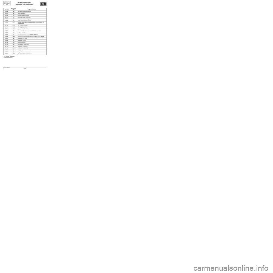
Tool faultAssociated
DTCDiagnostic tool title
DF089105Inletmanifold pressure sensor cir cuit
DF091500Vehicle speed signal
DF092130Upstream oxygen sensor circuit
DF093136Downstream oxygen sensor circuit
DF095120Th rottle potentiometer circuit gang1
DF096220Th rottle potentiometer circuit gang 2
DF099C101Automatic gearbox (BVA) or sequential gearbox (BVR) connection via
multiplex network
DF100C155TDB* multiplex connection
DF101C122ESP multiplex connection
DF1022502Signal: power sig.* available
DF106575Cruise control/Speed limiter selector switch on steering wheel
DF109313Low fuel level misfiring
DF119340Camshaft sensor signal (only for CLIO III or MODUS)
DF1261604Passenger compartment heating resistor (only for CLIO III or MODUS)
DF127703Brake switch no. 1 circuit
DF128571Brake switch 2 circuit
DF150830Clutch contact circuit
DF154335Flywheel signal sensor circuit
DF196225Pedal sensor circuit track 1
DF1982120Pedal sensor circuit track 2
DF228504Brake signal
DF232530Refrigerant pressure sensor circuit
DF2341335After-sales tooth signal sensor circuit
Page 42 of 348
17B-42V7 MR-413-X44-17B000$120.mif
PETROL INJECTION
Fault finding – Fault summary table17B
SIM 32 Injection
Program no.: D3
Vdiag No.: 44, 4C, 50
and 54
* TA: Automatic Transmission
* RV/LV: Cruise control/Speed limiter function
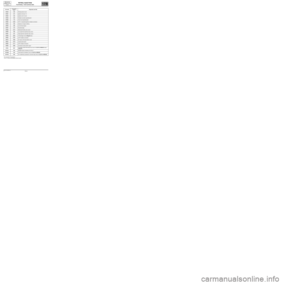
Tool faultAssociated
DTCDiagnostic tool title
DF330325Pinking sensor circuit
DF361351Ignition coil circuit 1-4
DF362352Ignition coil 2-3 circuit
DF394420Catalytic converter operating fault
DF398170Fuel circuit operating fault
DF404C302ATX* or sequential gearbox multiplex connection
DF436300Detection of engine misfiring
DF455460Low fuel level signal
DF457315Flywheel target
DF5082101Motorised throttle valve control
DF559480Low speed fan assembly relay control
DF561481High-speed fan assembly relay control
DF5692263Turbocharger circuit (Vdiag 54 only)
DF603C167UCH multiplex connection
DF6121605Oil vapour anti-icing resistor circuit
DF623C315Closing brake signal
DF624C111UPC multiplex connection
DF6502299Accelerator pedal position signal
DF8930597Controlled coolant thermostat circuit (only for CLIO III or MODUS except
Vdiag 44)
DF1012585Multiplex signal consistency for RV/LV*
DF1058234Inlet pressure consistency (only for CLIO III or MODUS)
DF1072645Air conditioning compressor command relay (only for CLIO III or MODUS)
Page 168 of 348
17B-168V7 MR-413-X44-17B000$150.mif
17B
SIM 32 Injection
Program no.: D3
Vdiag No.: 44, 4C, 50
and 54
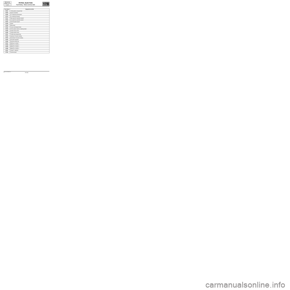
Tool statusDiagnostic tool title
ET001+ After ignition computer feed
ET003Engine immobiliser
ET004Air conditioning authorisation
ET018Air conditioning request
ET021High speed fan assembly request
ET022Low speed fan assembly request
ET023Fast idle speed request
ET038Engine
ET039Brake pedal
ET042Cruise control/speed limiter
ET045CC/SL selector switch on steering wheel
ET048Actuator relay control
ET050Canister bleed control
ET051Throttle stop programming
ET052Upstream O2 sensor heating
ET053Downstream O2 sensor heating
ET054Idle speed regulation
ET056Richness double loop
ET057Misfiring on cylinder 1
ET058Misfiring on cylinder 2
ET059Misfiring on cylinder 3
ET060Misfiring on cylinder 4
ET061Cylinder 1 detection
ET062Flywheel signal
PETROL INJECTION
Fault finding – Status summary table
Page 169 of 348
17B-169V7 MR-413-X44-17B000$150.mif
PETROL INJECTION
Fault finding – Status summary table17B
SIM 32 Injection
Program no.: D3
Vdiag No.: 44, 4C, 50
and 54
* RCH: passenger compartment heating resistor
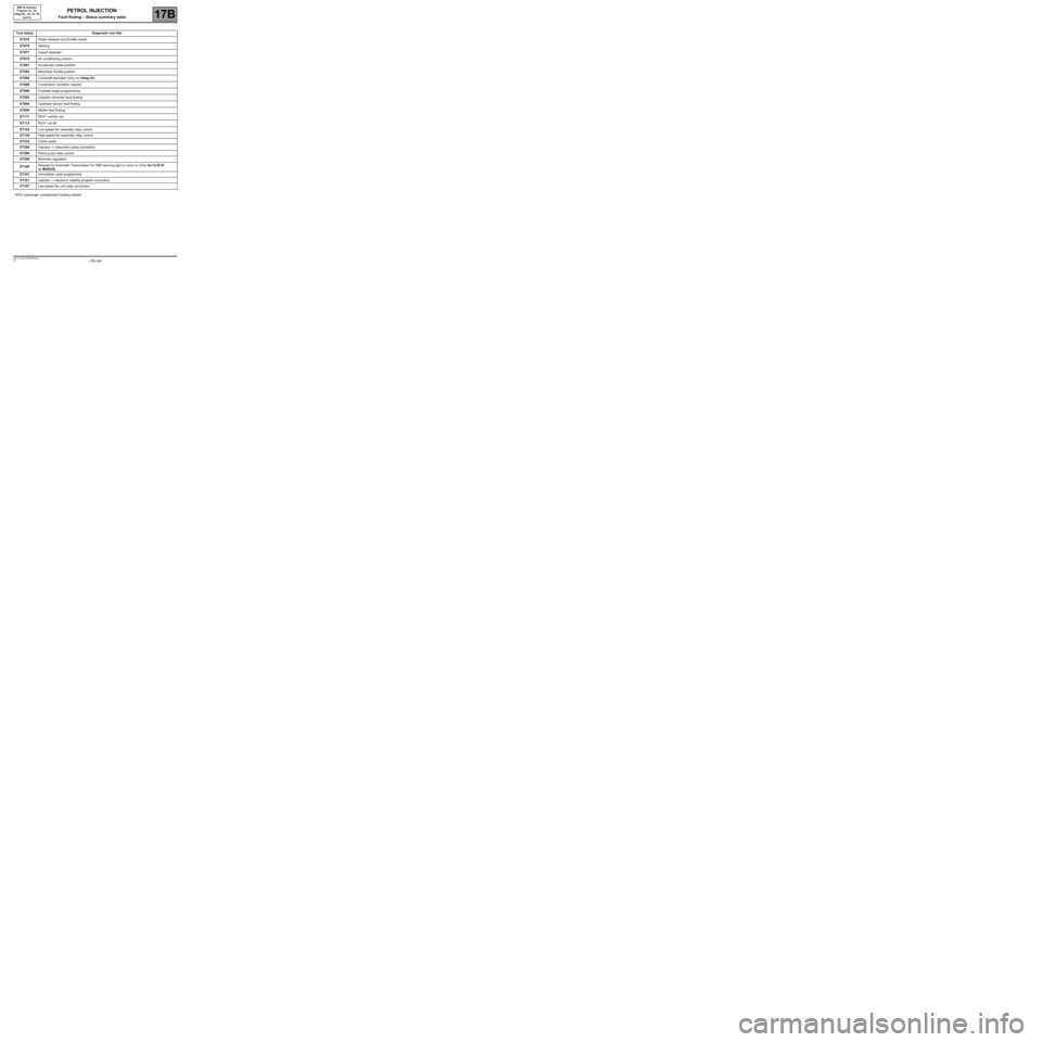
Tool statusDiagnostic tool title
ET075Pedal released and throttle closed
ET076Starting
ET077Impact detected
ET079Air conditioning present
ET081Accelerator pedal position
ET082Motorised throttle position
ET086Camshaft dephaser (Only for Vdiag 4C)
ET088Compressor actuation request
ET089Flywheel target programming
ET093Catalytic converter fault finding
ET094Upstream sensor fault finding
ET095Misfire fault finding
ET111RCH* number set
ET112RCH* cut-off
ET143Low-speed fan assembly relay control
ET144High-speed fan assembly relay control
ET233Clutch pedal
ET289Injection -> instrument panel connection
ET290Petrol pump relay control
ET300Richness regulation
ET340Request by Automatic Transmission for OBD warning light to come on (Only for CLIO III
or MODUS)
ET341Immobiliser code programmed
ET351Injection -> electronic stability program connection
ET357Low-speed fan unit relay connection
Page 170 of 348
17B-170V7 MR-413-X44-17B000$150.mif
PETROL INJECTION
Fault finding – Status summary table17B
SIM 32 Injection
Program no.: D3
Vdiag No.: 44, 4C, 50
and 54
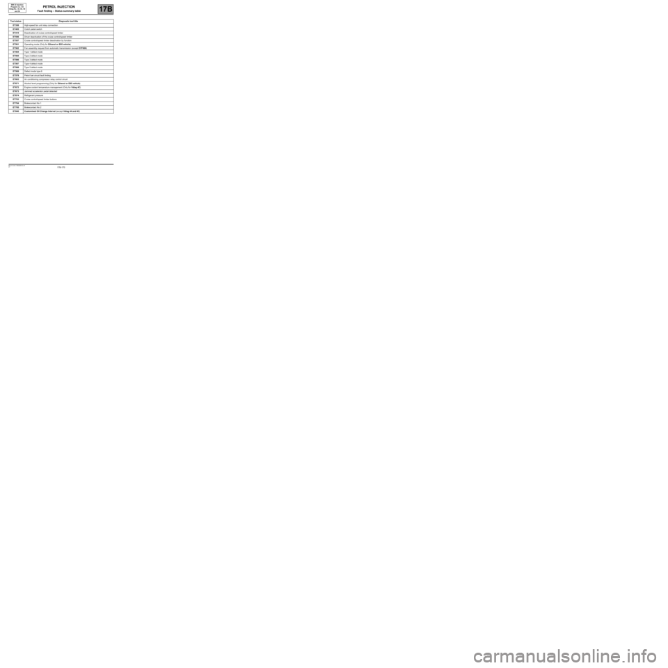
Tool statusDiagnostic tool title
ET358High-speed fan unit relay connection
ET405Clutch pedal switch
ET415Deactivation of cruise control/speed limiter
ET556Driver deactivation of the cruise control/speed limiter
ET557Cruise control/speed limiter deactivation by function
ET561Operating mode (Only for Ethanol or E85 vehicle)
ET562Fan assembly request from automatic transmission (except D7F800)
ET564Type 1 defect mode
ET565Type 2 defect mode
ET566Type 3 defect mode
ET567Type 4 defect mode
ET568Type 5 defect mode
ET569Defect mode type 6
ET578Petrol fuel circuit fault finding
ET603Air conditioning compressor relay control circuit
ET671Alcohol level programming (Only for Ethanol or E85 vehicle)
ET672Engine coolant temperature management (Only for Vdiag 4C)
ET673Jammed accelerator pedal detected
ET674Refrigerant pressure
ET703Cruise control/speed limiter buttons
ET704Brakecontact No 1
ET705Brakecontact No 2
ET840 Customised Oil Change Interval (except Vdiag 44 and 4C)
Page 263 of 348
17B-263V7 MR-413-X44-17B000$160.mif
17B
SIM 32 Injection
Program no.: D3
Vdiag No.: 44, 4C, 50
and 54
* OCR: Opening cyclic ratio
* EV: Solenoid valve
* mot: motorised
* app.: applying
* AAC: Camshaft
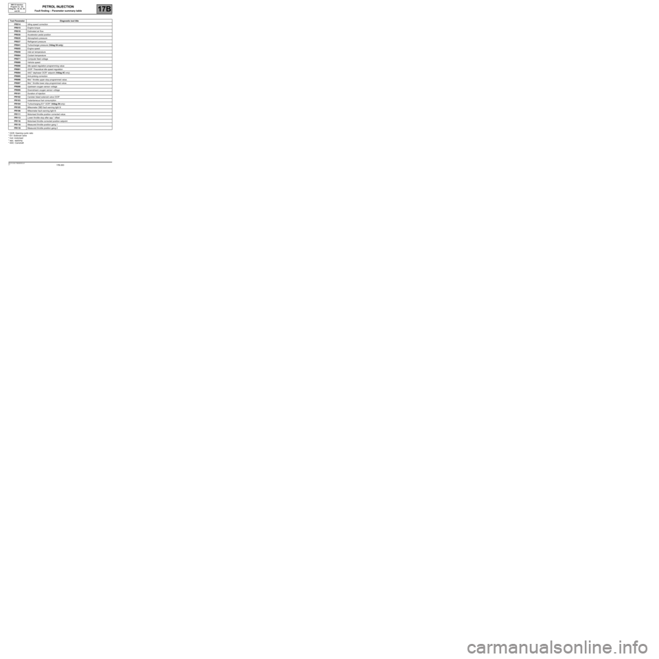
Tool ParameterDiagnostic tool title
PR014Idling speed correction
PR015Engine torque
PR018Estimated air flow
PR030Accelerator pedal position
PR035Atmospheric pressure
PR037Refrigerant pressure
PR041Turbocharger pressure (Vdiag 54 only)
PR055Engine speed
PR059Inlet air temperature
PR064Coolant temperature
PR071Computer feed voltage
PR089Vehicle speed
PR090Idle speed regulation programming value
PR091OCR* Theoretical idle speed regulation
PR094AAC* dephaser OCR* setpoint (Vdiag 4C only)
PR095Anti-pinking correction
PR096Mot.* throttle upper stop programmed value.
PR097Mot.* throttle lower stop programmed value.
PR098Upstream oxygen sensor voltage
PR099Downstream oxygen sensor voltage
PR101Duration of injection
PR102Canister bleed solenoid valve OCR*
PR103Instantaneous fuel consumption
PR104Turbocharging EV* OCR* (Vdiag 54 only)
PR105Mileometer OBD fault warning light lit
PR106Mileometer fault warning light lit
PR111Motorised throttle position corrected value.
PR113Lower throttle stop after app.* offset
PR116Motorised throttle corrected position setpoint
PR118Measured throttle position gang 1
PR119Measured throttle position gang 2
PETROL INJECTION
Fault finding – Parameter summary table