stop start RENAULT TWINGO 2009 2.G Electrical Equipment - Petrol Injection Workshop Manual
[x] Cancel search | Manufacturer: RENAULT, Model Year: 2009, Model line: TWINGO, Model: RENAULT TWINGO 2009 2.GPages: 348
Page 12 of 348

17B-12V7 MR-413-X44-17B000$030.mif
PETROL INJECTION
Fault finding – System operation17B
SIM 32 Injection
Program no.: D3
Vdiag No.: 44, 4C, 50
and 54
ET086: Camshaft dephaser control
FAULT: this defect mode covers all faults that affect the measurement of the dephaser position.
The dephaser is controlled at the lower stop and the camshaft angle measurement is forced to 0.
Tooth signal fault.
Tooth/camshaft signal consistency fault finding procedure.
This type covers all faults affecting the camshaft dephaser (pulley and solenoid valve)
●Electrical fault finding on the solenoid valve.
●The camshaft dephaser is controlled at the lower stop.
FAULT: this defect mode covers all faults that affect the dephaser (pulley and solenoid valve).
The dephaser is set to the low stop.
Electrical fault finding on the solenoid valve.
Dephaser position fault finding procedure.
This type groups together all faults affecting the measuring of the camshaft dephaser position.
●tooth signal fault
●tooth/camshaft signal consistency fault finding procedure
The VVT is controlled at the lower stop and the camshaft angle measurement is forced to the requested setpoint.
A first program called Memo phasing is applied to phase the engine management on starting according to the data
recorded at the last setting. It is therefore essential to wait until the end of the "powerlatch" phase (computer self-
supply phase enabling data to be saved which lasts for approximately 30 seconds) before starting any operations.
Then, a second program confirms the first decision. It is based on torque analysis.
Air supply
The idle speed regulator performs all of the calculations required for physical control of the idle speed actuator: the
motorised throttle. The functional component of the regulator is adaptive (variation programming and ageing).
If the idle speed regulation conditions are met, the status ET054 Idle speed regulation is "Active", and the idle
speed regulator continually positions the motorised throttle to maintain the engine speed at its idle reference value.
The motorised throttle opening ratio necessary to comply with the speed setpoint is then given by parameter
PR091 Idle speed regulation theoretical OCR.
The PR090 Idle speed regulation programming value is a stored parameter designed to "program" engine
variations and engine wear and tear for the idle speed regulator. The programming is carried out only when the
engine is idle and warm, and no electrical consumer (air conditioning, fan assembly, power assisted steering) is
operating. Therefore it adjusts slowly.
Page 14 of 348
17B-14V7 MR-413-X44-17B000$030.mif
PETROL INJECTION
Fault finding – System operation17B
SIM 32 Injection
Program no.: D3
Vdiag No.: 44, 4C, 50
and 54
Engine coolant temperature management
1. Conventional type thermostat
Engine cooling is performed by one or two fan assemblies (depending on the vehicle equipment). The injection
computer requests the UPC to actuate them via the multiplex network.
To ensure cooling, with the engine running, fan unit 1 is activated when the coolant temperature exceeds 99˚C and
stops when it drops below 96˚C.
Fan assembly 2 starts when the coolant temperature exceeds 102˚C and stops when it drops below 99˚C.
With the engine off, only fan assembly 1 may be activated to provide the anti-percolation function (if engine is
stopped when very hot). The anti-percolation function is active with the ignition off for a determined period. During
this time, fan assembly 1 is activated if the coolant temperature exceeds 100˚C and is deactivated when the
temperature drops below 95˚C.
If ET672: Engine coolant temperature management has a fault, then the temperature is regulated at 90˚C.
If a fault on the coolant temperature sensor circuit is detected, fan assembly 1 is activated and remains on all the
time.
If the engine coolant temperature exceeds the warning threshold of 118˚C, the injection computer directly
commands the coolant temperature warning light to come on or requests this action from the instrument panel
computer via the multiplex network, until the coolant temperature drops back below 115˚C.
As well as managing the engine, the injection computer centralises cooling requests for the air conditioning,
automatic transmission and sequential gearbox functions.
2. Controlled type thermostat
D4F 764 engines (with a camshaft dephaser solenoid valve) are fitted with a controlled coolant thermostat that
manages the engine at much higher coolant temperatures in order to reduce fuel consumption.
Description of operation
A conventional thermostat fitted with a heating resistor inside the wax core is used. The resistor is controlled by the
engine management computer by opening cycle ratio*.
In nominal operation, high coolant temperatures are managed in the engine in order to:
–reduce friction,
–reduce fuel consumption.
Nevertheless, defect operation mode is used to overcome faults linked to:
–reliability: at high engine speeds and high loads the engine temperature must be below 100˚C,
–performance: a high temperature increases chattering and reduces torque.
OCR*: Opening Cyclic Ratio.
Page 25 of 348
17B-25V7 MR-413-X44-17B000$060.mif
PETROL INJECTION
Fault finding – Features17B
SIM 32 Injection
Program no.: D3
Vdiag No.: 44, 4C, 50
and 54
Richness
For the catalytic converter to operate correctly, adjust around richness 1.
The richness regulation controlled by the upstream sensor which ensures a richness of around 1.
The upstream sensor supplies a voltage according to the image of the average engine richness: the voltage supplied
to the computer represents a Rich-Lean signal.
For the upstream sensor to be operational very rapidly, it is heated. The heating works only when the engine is
running. It is deactivated at speeds above 84 mph (140 km/h) or when the engine is under load.
The downstream sensor is also heated. The command does not activate immediately after starting the engine. It is
activated when the engine is running and has reached its operating temperature. The downstream heating sensor is
deactivated at speeds above 84 mph (140 km/h) or when the engine is under load.
Torque management
The torque structure is the system for managing engine torque. The torque structure is required for certain functions
such as the electronic stability program (ESP) or sequential gearbox (BVR).
Each computer (ESP, BVR) sends a request for torque via the multiplex network to the injection computer. This
intervenes between the torque requests received and the driver's requests (made via the pedal or the cruise control/
speed limiter function). The result of this intervention is the torque setpoint to be applied. Using the torque reference
value, the structure calculates the throttle position reference value and the ignition advance and if the turbocharging
function is present, calculates the turbocharging solenoid valve reference value.
Engine coolant temperature management
Engine cooling is performed by one or two fan assemblies (depending on the vehicle equipment). The injection
computer requests the UCH to actuate them via the multiplex network.
To provide cooling when the engine is running, activation of fan assembly 1 is requested if the coolant temperature
exceeds 99˚C and is deactivated when the temperature drops below 96˚C.
Fan unit 2 starts when the coolant temperature exceeds 102˚C and stops when it falls below 99˚C.
With the engine off, only GMV1 may be activated to provide the anti-percolation function (if engine is stopped when
very hot). The anti-percolation function is active with the ignition off for a determined period. During this time, fan
assembly 1 is activated if the coolant temperature exceeds 100˚C and is deactivated when the temperature drops
below 95˚C.
If the engine temperature exceeds the warning threshold of 118˚C, the injection computer directly commands the
coolant temperature warning light to illuminate or requests this action from the instrument panel computer via the
multiplex network, until the coolant temperature drops back below 115˚C.
As well as managing the engine, the injection computer handles cooling requirements for the air conditioning and
sequential gearbox functions.
Page 28 of 348
17B-28V7 MR-413-X44-17B000$070.mif
17B
SIM 32 Injection
Program no.: D3
Vdiag No.: 44, 4C, 50
and 54
1. OPERATING SAFETY
Activation of the warning lights
The SIM32 injection system manages the illumination of three warning lights according to the severity of the faults
detected, to inform the customer and to assist with fault finding.
The injection computer manages the activation of the warning lights on the instrument panel. These warning lights
illuminate during the starting phase and in the event of an injection fault or engine overheating.
The warning light activation commands are sent to the instrument panel.
Warning light illumination principle
When the ignition is switched on, the OBD (On Board Diagnostic) warning light is illuminated for approximately
3 seconds and is then extinguished.
If there is an injection fault (severity level 1), the SERVICE warning light is illuminated.
It indicates a reduced level of operation and a limited safety level.
The user must carry out repairs as soon as possible:
–motorised throttle valve,
–accelerator pedal potentiometer,
–inlet manifold pressure sensor,
–computer,
–actuator feed,
–the computer power supply,
–turbocharger pressure sensor (for D4FT 780).
For faults requiring the driver to stop the engine quickly, the severity level 2 warning light is illuminated.
If a fault causing excessive exhaust gas pollution is detected, the orange OBD warning light engine symbol is
illuminated:
–the light flashes if the fault could lead to a risk of destroying catalytic converter (destructive engine misfire). If this
happens, the vehicle must be stopped immediately.
–the light is permanently illuminated if the emission control standards are not met (pollutant engine misfire,
catalytic converter fault, oxygen sensor fault, inconsistency between the oxygen sensors and a fuel vapour
absorber fault).
Mileage travelled with fault
The parameter PR106 Mileage counter fault warning light illuminated displays the mileage covered and
illuminates one of the injection fault warning lights: fault severity level 1 (amber) and 2 (red). The parameter
PR105 Mileage counter OBD fault warning light illuminated displays the mileage covered and illuminates the
OBD warning light.
This counter is reset to 0 using the diagnostic tool via the command RZ001 Fault memory.
PETROL INJECTION
Fault finding – Role of components
Page 36 of 348
17B-36V7 MR-413-X44-17B000$090.mif
PETROL INJECTION
Fault finding – Replacement of components17B
SIM 32 Injection
Program no.: D3
Vdiag No.: 44, 4C, 50
and 54
PROCEDURE:
Before any computer programming, only Vdiag 54 and 50 (see previous page):
–Run the command SC003 'Save computer data.
Any time the computer has been programmed
–Switch the ignition off and then on again.
–Select the UCH domain using the diagnostic tool.
–In repair mode, run the command SC017 "Programming the injection immobiliser code" and follow the
instructions given by the diagnostic tool.
–Switch the ignition off and then on again.
–Select the INJECTION subgroup and check status ET341 Immobiliser code programmed.
–Run the command SC001 ''Write saved data" Vdiag 54 only.
IF ET341 = YES
–Start and then stop the engine (to initialise the computer) and wait 30 seconds.
–Switch the ignition back on and use the diagnostic tool to carry out the following steps:
–Run the command VP010 Write VIN.
–After injection system programming, stored faults may appear on other computers. Clear the memory of
these computers.
IF ET341: NO
–Re-run command SC017 and follow the instructions given by the diagnostic tool.
2. COMPUTER REPROGRAMMING OPERATIONS
When replacing or removing the TDC sensor, program the engine flywheel ring (see Configurations and
programming).
3. REPLACING THE MOTORISED THROTTLE VALVE
When replacing the throttle valve, program the throttle stops (see Configurations and programming).
4. REPLACING THE MOTORISED THROTTLE VALVE
When replacing the throttle valve, program the throttle stops (see Configurations and programming). IMPORTANT:
AFTER A PROGRAMMING OPERATION, DO NOT DISCONNECT THE BATTERY FOR AT LEAST
30 MINUTES (to carry out other work on the vehicle).
IMPORTANT:
Never drive the vehicle without having programmed the throttle stops.
Page 39 of 348
17B-39V7 MR-413-X44-17B000$110.mif
17B
SIM 32 Injection
Program no.: D3
Vdiag No.: 44, 4C, 50
and 54
2. PROGRAMMING
Flywheel target programming
(To be carried out when replacing or removing the TDC sensor).
The coolant temperature must be over 35˚C.
–Carry out an initial deceleration with injection cut-off (feet off the brake, accelerator and clutch pedals) between
3500 and 3000 rpm, in 3rd gear for at least 5 seconds for manual gearboxes.
–Decelerate a second time with injection cut-off (feet off the brake, accelerator and clutch pedals) between 2400 and
2000 rpm, in 3rd gear for at least 5 seconds for manual gearboxes.
Check the programming with ET089 Programming flywheel target: Performed.
Programming the throttle end stops
After replacement of the computer or the motorised throttle valve, with the ignition on, wait 30 seconds so that the
computer can program the Upper and Lower limits and then switch off the ignition and wait 30 seconds for the end of
the "Power Latch", so that the computer can store the programmed limits. Check the programming with ET051
Programming throttle stops: Performed.
Programming the alcohol level (only for vehicles running on Ethanol or E85 fuel)
Fuel recognition is carried out by observing the drift of the richness controller.
This can only be performed if the mixture regulation is looped (ET300 Mixture regulation).
Programming procedure:
–start the engine,
–wait for the engine coolant temperature to reach 75˚C and then check using the parameter PR064 "Coolant
temperature",
–run the engine at 1500 rpm for a period of at least 5 minutes,
–check that the programming has been carried out using status ET671 Alcohol level programming and
parameter PR743 Estimated alcohol level in tank,
–the programming is saved when the ignition is switched off. Note:
After replacement of the throttle valve run the command RZ005 Programming to erase any recorded
programming.
Note:
When the injection computer has not recognised the fuel composition, operation is faulty.
PETROL INJECTION
Fault finding – Programming
Page 105 of 348
17B-105V7 MR-413-X44-17B000$132.mif
PETROL INJECTION
Fault finding – Interpretation of faults17B
SIM 32 Injection
Program no.: D3
Vdiag No.: 44, 4C, 50
and 54
DF092
CONTINUED
Run command SC007 Run OBD Test: O2 sensors.
The aim of this scenario is to detect a fault causing the EOBD* threshold for pollutant emissions to be exceeded.
There are two kinds of oxygen sensor damage:
–mechanical damage to the component (breakage, cut in wire) which leads to an electrical fault,
–chemical or thermal damage to the component leading to a slower response time of the sensor and to the
increase in the average reaction time.
Before carrying out this test, repair all the electrical faults and clear the fault memory.
Deal first with the DF436 Misfiring detection fault and program the flywheel target ET089 Flywheel target
programming.
Perform this test when the engine is warm, which reduces the time it takes for the catalytic converter to heat up.
Fault finding is entirely autonomous. When completed, the throttle control ceases and the engine returns to idling
speed regulation operation.
At the end of this test, four different results are possible:
–status 1: Fault finding not carried out/impossible to establish the necessary conditions.
–status 2: Component in an average condition.
–status 3: Component in good condition.
–status 4: Component in poor condition.
When fault finding is completed and the result read, stop the engine and start it again to establish normal operating
conditions.
If the result is status 1: check for any faults, and the engine flywheel target programming using ET089
Programming engine flywheel target.
If the result is status 2 or status 4, replace the sensor.
If the result is status 3, the sensor is in good condition.
If the fault is still present, contact the Techline.
AFTER REPAIRIf the throttle valve has been replaced, program the throttle stops, RZ005 Programming.
Follow the instructions to confirm repair:
- If the fault is present, continue to deal with the fault.
- If the fault is stored, ignore it.
Deal with any other faults.
Clear the stored faults.
Page 142 of 348
17B-142V7 MR-413-X44-17B000$133.mif
PETROL INJECTION
Fault finding – Interpretation of faults17B
SIM 32 Injection
Program no.: D3
Vdiag No.: 44, 4C, 50
and 54
DF394
PRESENT
OR
STOREDCATALYTIC CONVERTER OPERATING FAULT
1.DEF: Component in bad condition
2.DEF: EOBD
NOTESPriorities when dealing with a number of faults:
Deal with any other fault first.
Conditions for applying the fault finding procedure to stored faults:
The fault is declared present after the engine starts.
Special notes:
The OBD warning light is lit.
Use the Wiring Diagrams Technical Note for NEW TWINGO, E33, CLIO III,
or MODUS.
Only for Vdiag 4C, 50 and 54
Check the appearance and condition of the catalytic converter. Check there are no air leaks, thermal shock,
misfiring, coolant or oil consumption.
Run command SC006 Running OBD Test: catalytic converter. Before carrying out this test, repair all the
electrical faults and clear the fault memory. Check that fault DF436 Misfiring detection is not present and program
the engine flywheel target ET089 Flywheel target programming.
Carry out this test when the engine is warm, which reduces the time it takes for the catalytic converter to heat up.
At the end of this test, four different results are possible:
–Status 1: Fault finding not carried out/impossible to obtain the necessary conditions.
–Status 2: Component in an average condition.
–Status 3: Component in good condition.
–Status 4: Component in poor condition.
When fault finding is completed and the result read, stop the engine and start it again to establish normal operating
conditions.
If the result is status 1: check that there are no faults, and check the engine flywheel target programming using
ET089 Programming engine flywheel target.
If the result is status 2 or 4: replace the catalytic converter.
If the result is status 3: the catalytic converter is in good condition.
If the fault is still present, contact the Techline.
SIM32_V44_DF394/SIM32_V4C_DF394/SIM32_V50_DF394/SIM32_V54_DF394
AFTER REPAIREnsure that all the faults have been dealt with.
Clear the stored faults. Do not clear the programming.
To check that the system has been properly repaired:
–there must be no further electrical faults,
–programming has been carried out,
the engine must be warm (minimum 75˚C), and idling, with all electrical consumers
running for 15 minutes.
Page 175 of 348
17B-175V7 MR-413-X44-17B000$151.mif
PETROL INJECTION
Fault finding – Interpretation of statuses17B
SIM 32 Injection
Program no.: D3
Vdiag No.: 44, 4C, 50
and 54
ET021HIGH-SPEED FAN REQUEST–Active
–Inactive
STATUS
DEFINITIONACTIVE: This status indicates that the high-speed fan assembly is active.
INACTIVE: This status indicates that the high-speed fan assembly is inactive.
NOTESSpecial notes:
Apply the checks only if statuses ACTIVE and INACTIVE are inconsistent.
Refer to the Wiring Diagrams Technical Note for NEW TWINGO, E33, CLIO III
or MODUS.
Conformity check: Engine stopped and ignition on, or engine running at idle speed, and engine coolant
temperature > 80˚C.
"ACTIVE"
or
"INACTIVE"Fan unit 2 starts when the coolant temperature exceeds 102˚C and stops when it falls
below 99˚C.
Sensor electrical conformity
SIM32_V44_ET021/SIM32_V4C_ET021/SIM32_V50_ET021/SIM32_V54_ET021
AFTER REPAIRCarry out a road test, then check with the diagnostic tool.
Repeat the conformity check from the start.
Page 178 of 348
17B-178V7 MR-413-X44-17B000$151.mif
PETROL INJECTION
Fault finding – Interpretation of statuses17B
SIM 32 Injection
Program no.: D3
Vdiag No.: 44, 4C, 50
and 54
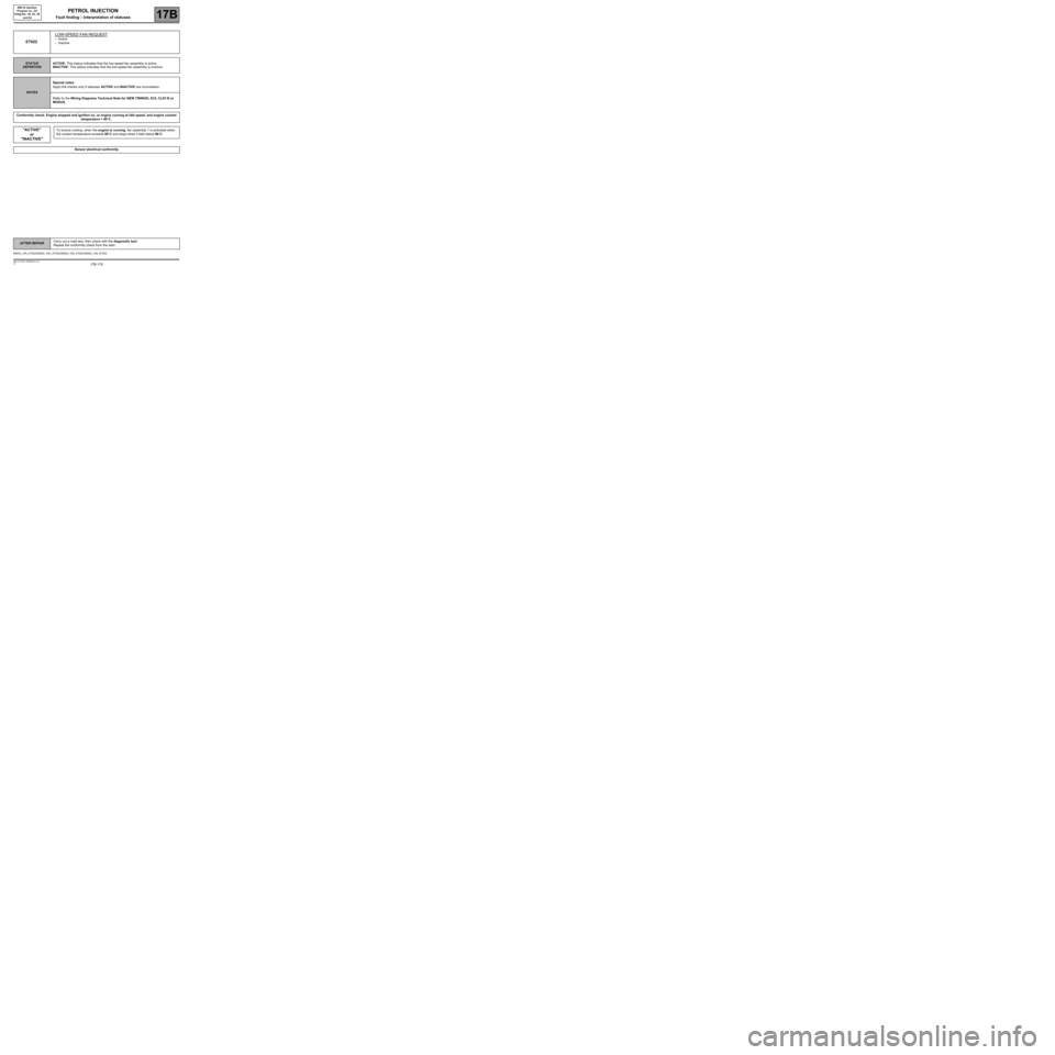
ET022LOW-SPEED FAN REQUEST–Active
–Inactive
STATUS
DEFINITIONACTIVE: This status indicates that the low-speed fan assembly is active.
INACTIVE: This status indicates that the low-speed fan assembly is inactive.
NOTESSpecial notes:
Apply the checks only if statuses ACTIVE and INACTIVE are inconsistent.
Refer to the Wiring Diagrams Technical Note for NEW TWINGO, E33, CLIO III or
MODUS.
Conformity check: Engine stopped and ignition on, or engine running at idle speed, and engine coolant
temperature > 80˚C.
"ACTIVE"
or
"INACTIVE"To ensure cooling, when the engine is running, fan assembly 1 is activated when
the coolant temperature exceeds 99˚C and stops when it falls below 96˚C.
Sensor electrical conformity
SIM32_V44_ET022/SIM32_V4C_ET022/SIM32_V50_ET022/SIM32_V54_ET022
AFTER REPAIRCarry out a road test, then check with the diagnostic tool.
Repeat the conformity check from the start.