RENAULT TWINGO 2009 2.G Electrical Equipment User Guide
Manufacturer: RENAULT, Model Year: 2009, Model line: TWINGO, Model: RENAULT TWINGO 2009 2.GPages: 241
Page 11 of 241
80A-5
BATTERY
Battery: Removal - Refitting
80A
aPush the positive battery terminal fully onto the posi-
tive terminal post into the position marked during the
removal operation.
aTorque tighten the positive battery terminal nut (8
N.m).
aConnect the positive battery terminal wiring.
aTorque tighten the stud nut on the positive battery
terminal (12 N.m).
a
(see 80A, Battery, Battery: Precautions for the
repair, page 80A-1) .
2 - CONNECTION
a
aPush the negative battery terminal onto the negative
terminal post into the position marked during the re-
moval operation.
aTorque tighten the negative battery terminal nut (8
N.m).
aConnect the wiring to the negative battery terminal.
aTorque tighten the stud nut on the negative batte-
ry terminal (6 N.m).
(see 80A, Battery, Battery: Precautions for the
repair, page 80A-1) .
III - FINAL OPERATION
aRefit the battery cover.
aWhen refitting the battery or each time it is discon-
nected, carry out a certain number of operations, wi-
thout using the diagnostic tool, so that the vehicle
can operate correctly (see Battery: Initialisation)
(80A, Battery).WARNING
Poor contact may cause starting or charging
faults, create sparks and cause the battery to
explode.
WARNING
To prevent premature loosening of the stud nuts
on the negative terminal, refit a maximum of two
terminals per stud and distribute the terminals
over different studs.
WARNING
Poor contact may cause starting or charging
faults, create sparks and cause the battery to
explode.
Page 12 of 241
80A-6
BATTERY
Battery tray: Removal - Refitting
80A
REMOVAL
I - REMOVAL PREPARATION OPERATION
aRemove the battery (see 80A, Battery, Battery: Re-
moval - Refitting, page 80A-2) .
II - OPERATION FOR REMOVAL OF PART
CONCERNED
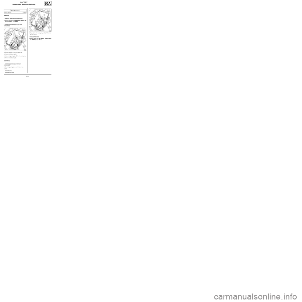
aRemove the bolts (1) from the battery tray.
aTake out the battery tray (3) .
aUnclip the degassing pipe (2) from the battery tray.
aRemove the battery tray (3) .
REFITTING
I - REFITTING OPERATION FOR PART
CONCERNED
aClip the degassing pipe onto the battery tray.
aRefit:
-the battery tray,
-the battery tray bolts,aTorque tighten the battery tray bolts (21 N.m) in or-
der (4) , (5) , (6) .
II - FINAL OPERATION
aRefit the battery (see 80A, Battery, Battery: Remo-
val - Refitting, page 80A-2) . Tightening torquesm
battery tray bolts21 N.m
119372
119372
Page 13 of 241
80B-1
HEADLIGHTS
Front lighting: List and location of components
80B
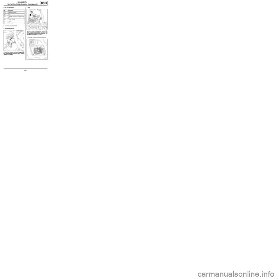
I - LIST OF COMPONENTS
II - LOCATION OF COMPONENTS
1 - Signalling light switch
To remove the signalling light switch (see 84A, Con-
trol - Signals, Signals and lighting switch: Removal
- Refitting, page 84A-8) .2 - UCH
The UCH is located in the dashboard, above the pas-
senger compartment relay/fuse box, for removal (see
87B, Passenger compartment connection unit,
UCH: Removal - Refitting, page 87B-1) .
3 - Passenger compartment fuse and relay box No. Description
(1) Signalling light switch
(2) UCH
(3) Passenger compartment fuse and relay
box
(4) Halogen headlight
(5) Fog light
(6) Side indicator
121133
119507
119504
Page 14 of 241
80B-2
HEADLIGHTS
Front lighting: List and location of components
80B
4 - Halogen headlight
5 - Fog light6 - Side indicator
121210
121210
121205
Page 15 of 241
80B-3
HEADLIGHTS
Halogen bulb: Removal - Refitting
80B
REMOVAL
I - REMOVAL PREPARATION OPERATION
aSwitch off the ignition.
II - REMOVAL OPERATION FOR PART
CONCERNED
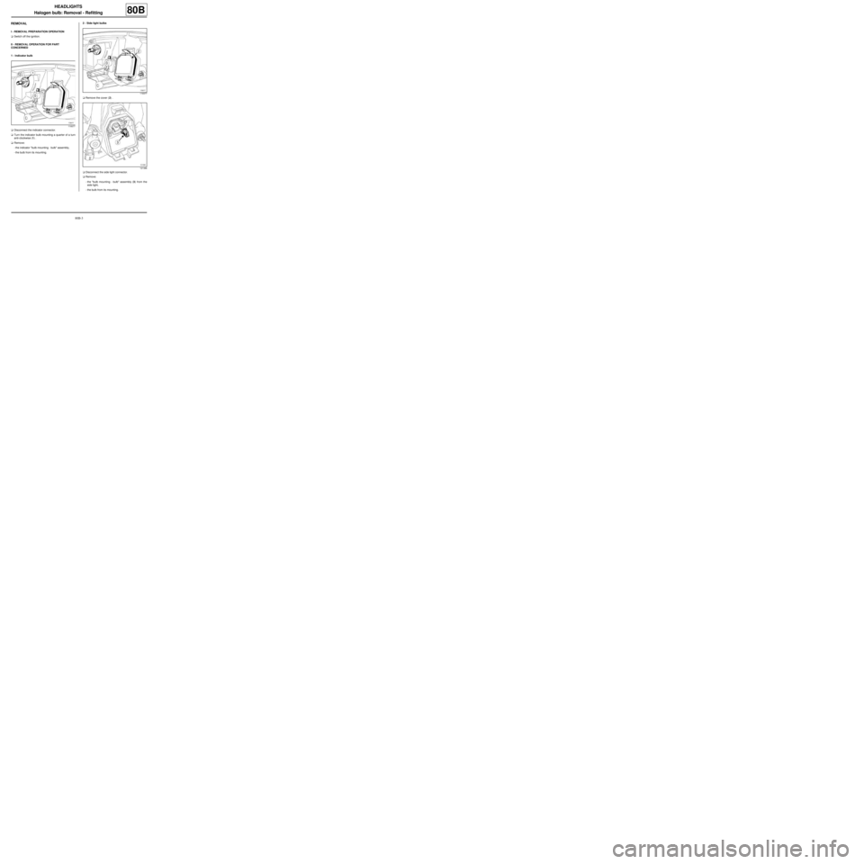
1 - Indicator bulb
aDisconnect the indicator connector.
aTurn the indicator bulb mounting a quarter of a turn
anti-clockwise (1) .
aRemove:
-the indicator "bulb mounting - bulb" assembly,
-the bulb from its mounting.2 - Side light bulbs
aRemove the cover (2) .
aDisconnect the side light connector.
aRemove:
-the "bulb mounting - bulb" assembly (3) from the
side light,
-the bulb from its mounting.
119377
119377
121386
Page 16 of 241
80B-4
HEADLIGHTS
Halogen bulb: Removal - Refitting
80B
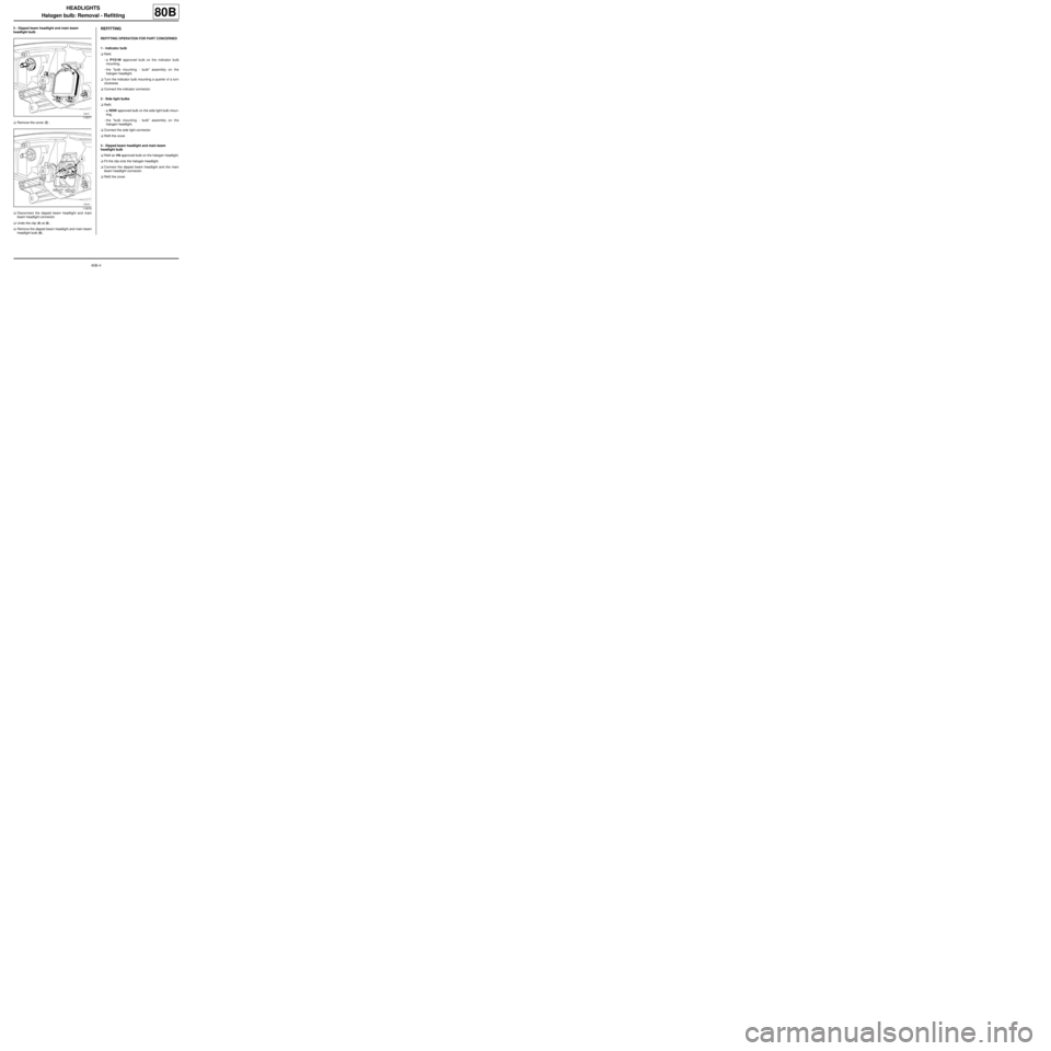
3 - Dipped beam headlight and main beam
headlight bulb
aRemove the cover (2) .
aDisconnect the dipped beam headlight and main
beam headlight connector.
aUndo the clip (4) at (5) .
aRemove the dipped beam headlight and main beam
headlight bulb (6) .REFITTING
REFITTING OPERATION FOR PART CONCERNED
1 - Indicator bulb
aRefit:
-a PY21W approved bulb on the indicator bulb
mounting,
-the "bulb mounting - bulb" assembly on the
halogen headlight.
aTurn the indicator bulb mounting a quarter of a turn
clockwise.
aConnect the indicator connector.
2 - Side light bulbs
aRefit:
-a W5W approved bulb on the side light bulb moun-
ting,
-the "bulb mounting - bulb" assembly on the
halogen headlight.
aConnect the side light connector.
aRefit the cover.
3 - Dipped beam headlight and main beam
headlight bulb
aRefit an H4 approved bulb on the halogen headlight.
aFit the clip onto the halogen headlight.
aConnect the dipped beam headlight and the main
beam headlight connector.
aRefit the cover.
119377
119378
Page 17 of 241
80B-5
HEADLIGHTS
Remote headlight beam adjustment motor: Removal - Refitting80B
REMOVAL
I - REMOVAL PREPARATION OPERATION
aPosition the vehicle on a two-post lift (see Vehicle:
Towing and lifting) (MR 411, 02A, Lifting equip-
ment).
aRemove:
-the front wheels (see Wheel: Removal - Refitting)
(MR 411, 35A, Wheels and tyres),
-the front wheel arch liners (see Front wheel arch
liner: Removal - Refitting) (MR 412, 55A, Exterior
protection),
-the front bumper (see Front bumper: Removal -
Refitting) (MR 412, 55A, Exterior protection),
-the headlights (see 80B, Headlights, Halogen
headlight: Removal - Refitting, page 80B-7) .II - OPERATION FOR REMOVAL OF PART
CONCERNED
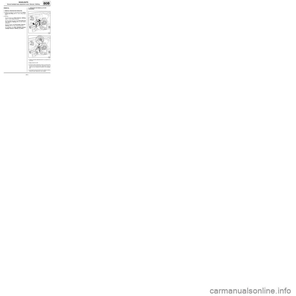
aTighten the beam adjustment bolt (1) (a maximum of
six turns).
aApply pressure to (2) .
aUnclip the beam adjustment motor by removing the
clip (3) and turning the beam adjustment motor an
eighth of a turn towards the outside of the headlight
(4) .
aUncouple the ball joint (5) from the reflector shell by
tilting the beam adjustment motor slightly.
119379
119380
Page 18 of 241
80B-6
HEADLIGHTS
Remote headlight beam adjustment motor: Removal - Refitting80B
REFITTING
I - REFITTING OPERATION FOR PART
CONCERNED
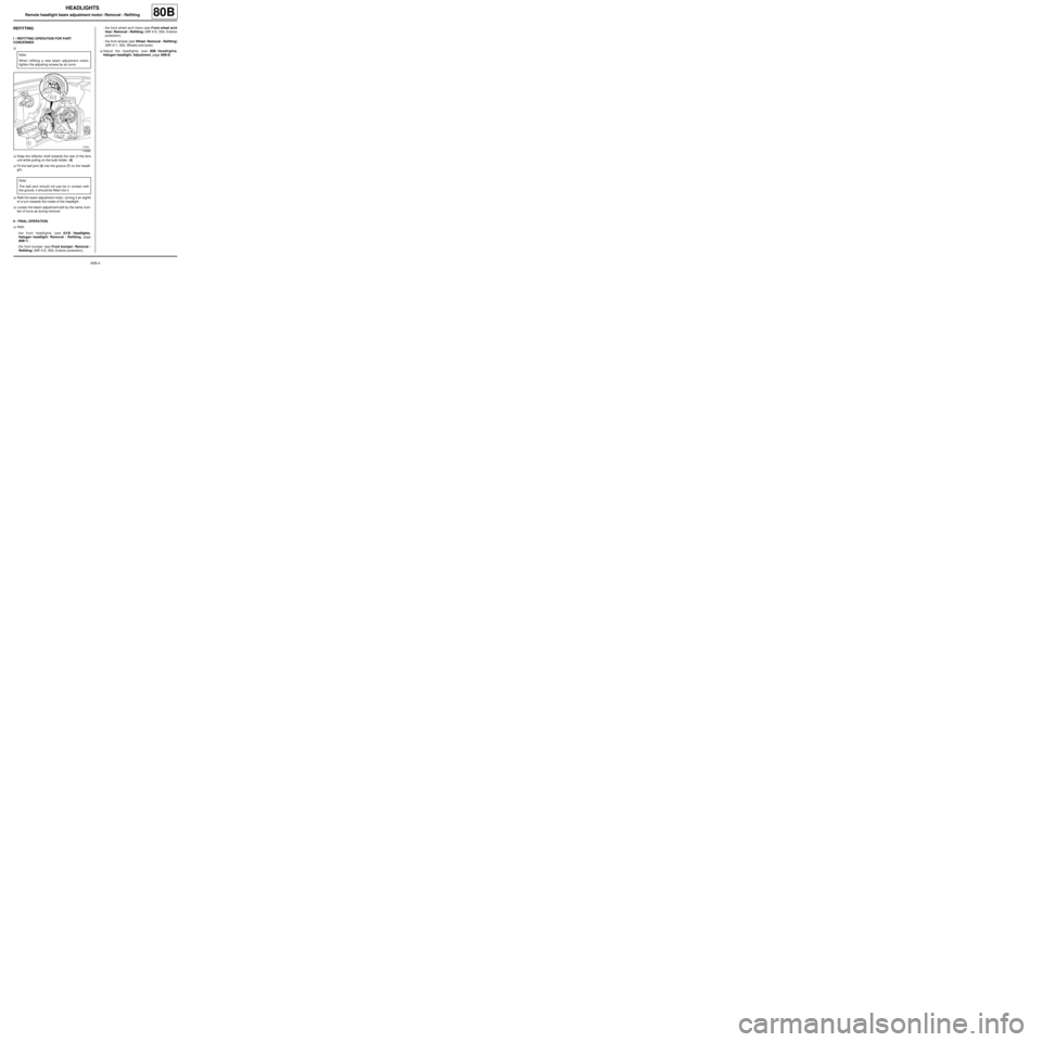
a
aKeep the reflector shell towards the rear of the lens
unit while pulling on the bulb holder. (6)
aFit the ball joint (5) into the groove (7) on the headli-
ght.
aRefit the beam adjustment motor, turning it an eighth
of a turn towards the inside of the headlight.
aLoosen the beam adjustment bolt by the same num-
ber of turns as during removal.
II - FINAL OPERATION.
aRefit:
-the front headlights (see 80B, Headlights,
Halogen headlight: Removal - Refitting, page
80B-7) ,
-the front bumper (see Front bumper: Removal -
Refitting) (MR 412, 55A, Exterior protection),-the front wheel arch liners (see Front wheel arch
liner: Removal - Refitting) (MR 412, 55A, Exterior
protection),
-the front wheels (see Wheel: Removal - Refitting)
(MR 411, 35A, Wheels and tyres).
aAdjust the headlights (see 80B, Headlights,
Halogen headlight: Adjustment, page 80B-9) . Note:
When refitting a new beam adjustment motor,
tighten the adjusting screws by six turns.
119380
Note:
The ball joint should not just be in contact with
the groove, it should be fitted into it.
Page 19 of 241
80B-7
HEADLIGHTS
Halogen headlight: Removal - Refitting
80B
REMOVAL
I - REMOVAL PREPARATION OPERATION
aPosition the vehicle on a two-post lift (see Vehicle:
Towing and lifting) (MR 411, 02A, Lifting equip-
ment).
aSwitch off the ignition.
aRemove:
-the front wheels (see Wheel: Removal - Refitting)
(MR 411, 35A, Wheels and tyres),
-the front wheel arch liners (see Front wheel arch
liner: Removal - Refitting) (MR 412, 55A, Exterior
protection),
-the front bumper (see Front bumper: Removal -
Refitting) (MR 412, 55A, Exterior protection).II - REMOVAL OPERATION FOR PART
CONCERNED
aRemove the bolts (1) from the halogen headlight.
aRemove the halogen headlight.
119376
119375
Page 20 of 241
80B-8
HEADLIGHTS
Halogen headlight: Removal - Refitting
80B
aRemove the cover (2) from the halogen headlight.
aDisconnect the halogen headlight connectors.
aRemove:
-the headlight,
-the halogen headlight bulbs (see 80B, Headlights,
Halogen bulb: Removal - Refitting, page 80B-3) .
REFITTING
I - REFITTING OPERATION FOR PART
CONCERNED
aRefit the halogen headlight bulbs (see 80B, Headli-
ghts, Halogen bulb: Removal - Refitting, page
80B-3) .
aConnect the halogen headlight connectors.
aRefit:
-the halogen headlight cover,
-the halogen headlight,
-the halogen headlight bolts.
II - FINAL OPERATION.
aRefit:
-the front bumper (see Front bumper: Removal -
Refitting) (MR 412, 55A, Exterior protection),
-the front wheel arch liners (see Front wheel arch
liner: Removal - Refitting) (MR 412, 55A, Exterior
protection),-the front wheels (see Wheel: Removal - Refitting)
(MR 411, 35A, Wheels and tyres).
aAdjust the halogen headlights (see 80B, Headli-
ghts, Halogen headlight: Adjustment, page 80B-
9) .
119377