dashboard RENAULT TWINGO 2009 2.G Electrical Equipment User Guide
[x] Cancel search | Manufacturer: RENAULT, Model Year: 2009, Model line: TWINGO, Model: RENAULT TWINGO 2009 2.GPages: 241
Page 119 of 241
87C-1
OPENING ELEMENT MANAGEMENT
Opening elements management: List and location of components87C
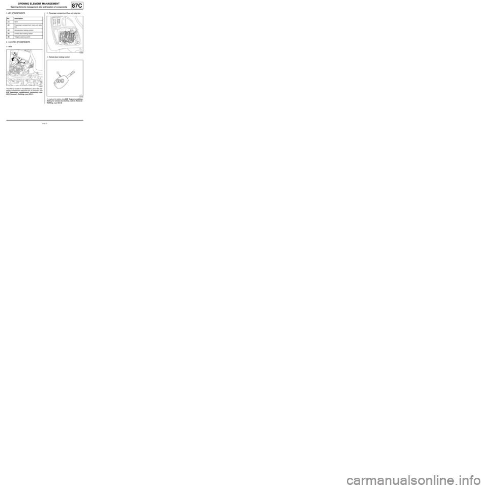
I - LIST OF COMPONENTS
II - LOCATION OF COMPONENTS
1 - UCH
The UCH is located in the dashboard, above the pas-
senger compartment relay/fuse box; to remove it (see
87B, Passenger compartment connection unit,
UCH: Removal - Refitting, page 87B-1) .2 - Passenger compartment fuse and relay box
3 - Remote door locking control
To replace the battery (see 82A, Engine immobiliser,
Battery for remote door locking control: Removal -
Refitting, page 82A-8) . No. Description
(1) UCH
(2) Passenger compartment fuse and relay
box
(3) Remote door locking control
(4) Centr al door locking switch
(5) Tailgate opening switch
119507
119504
107733
Page 123 of 241
87D-2
ELECTRIC WINDOWS - SUNROOF
Electric sunroof: List and location of components
OPENING ROOF
87D
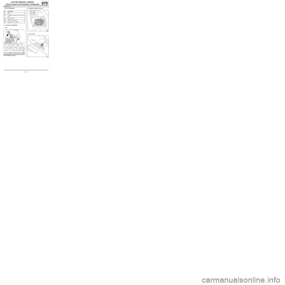
I - LIST OF COMPONENTS
II - LOCATION OF COMPONENTS
1 - UCH
The UCH is located in the dashboard, above the pas-
senger compartment relay unit; to remove it (see 87B,
Passenger compartment connection unit, UCH: Re-
moval - Refitting, page 87B-1) .2 - Passenger compartment relay unit
3 - Sunroof switch No. Description
(1) UCH
(2) Passenger compartment fuse and relay
box
(3) Sunroof switch
(4) Sunroof moving panel
(5) Sunroof motor - computer
119507
119504
121391
Page 131 of 241
87F-1
PARKING DISTANCE CONTROL
Parking distance control: List and location of components
REAR PROXIMITY RADAR
87F
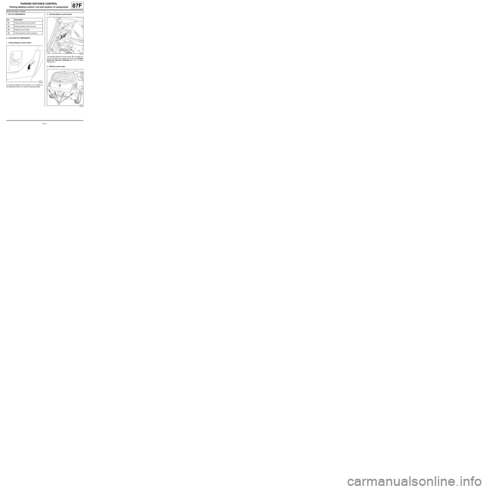
I - LIST OF COMPONENTS
II - LOCATION OF COMPONENTS
1 - Parking distance control switch
The parking distance control switch (1) is located on
the dashboard lower trim under the steering wheel.2 - Parking distance control buzzer
The parking distance control buzzer (2) is located un-
der the left-hand rear quarter panel trim (see Quarter
panel trim: Removal - Refitting) (MR 412, 71A, Body
internal trim).
3 - Distance control radar No. Description
(1) Parking distance control switch
(2) Parking distance control buzzer
(3) Distance control radar
(4) Parking distance control computer
121372
121367
121374
Page 133 of 241
87F-3
PARKING DISTANCE CONTROL
Parking distance control switch: Removal - Refitting
REAR PROXIMITY RADAR
87F
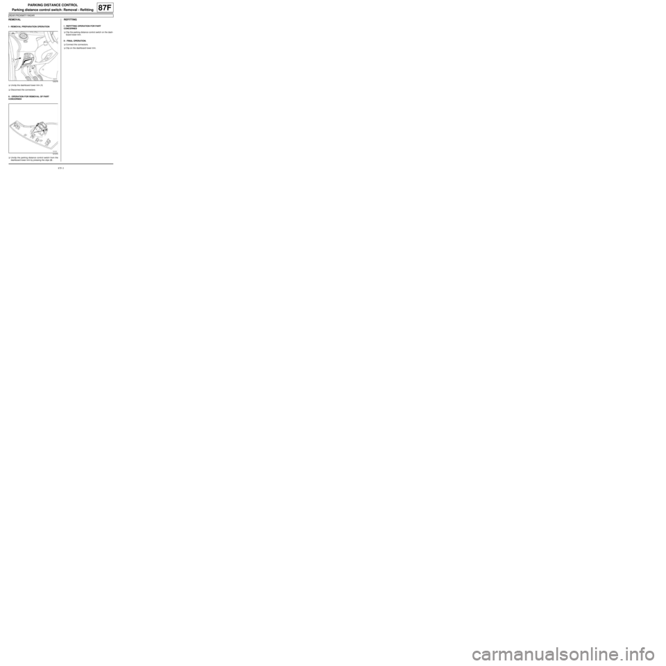
REMOVAL
I - REMOVAL PREPARATION OPERATION
aUnclip the dashboard lower trim (1)
aDisconnect the connectors.
II - OPERATION FOR REMOVAL OF PART
CONCERNED
aUnclip the parking distance control switch from the
dashboard lower trim by pressing the clips (2) .
REFITTING
I - REFITTING OPERATION FOR PART
CONCERNED
aClip the parking distance control switch on the dash-
board lower trim.
II - FINAL OPERATION.
aConnect the connectors.
aClip on the dashboard lower trim.
120278
121373
Page 139 of 241
88A-3
WIRING HARNESS
Front left-hand wiring: Removal - Refitting
LEFT-HAND DRIVE
88A
REMOVAL
I - REMOVAL PREPARATION OPERATION
a
aPosition the vehicle on a two-post lift (see Vehicle:
Towing and lifting) (MR 411, 02A, Lifting equip-
ment).
aSwitch off the ignition.
aRemove:
-the battery (see 80A, Battery, Battery: Removal -
Refitting, page 80A-2) ,
-the battery tray (see 80A, Battery, Battery tray:
Removal - Refitting, page 80A-6) ,
-the front wheel arch liners (see Front wheel arch
liner: Removal - Refitting) (MR 412, 55A, Exterior
protection),
-the front bumper (see Front bumper: Removal -
Refitting) (MR 412, 55A, Exterior protection),
-the side indicators (see 80B, Headlights, Side in-
dicator: Removal - Refitting, page 80B-13) ,
-the master cylinder (see Master cylinder: Remo-
val - Refitting) (MR 411, 37A, Mechanical compo-
nent controls),
-the brake servo (see Brake servo: Removal - Re-
fitting) (MR 411, 37A, Mechanical component con-
trols),
-the left-hand suspended engine mounting (see
Left-hand suspended engine mounting: Remo-
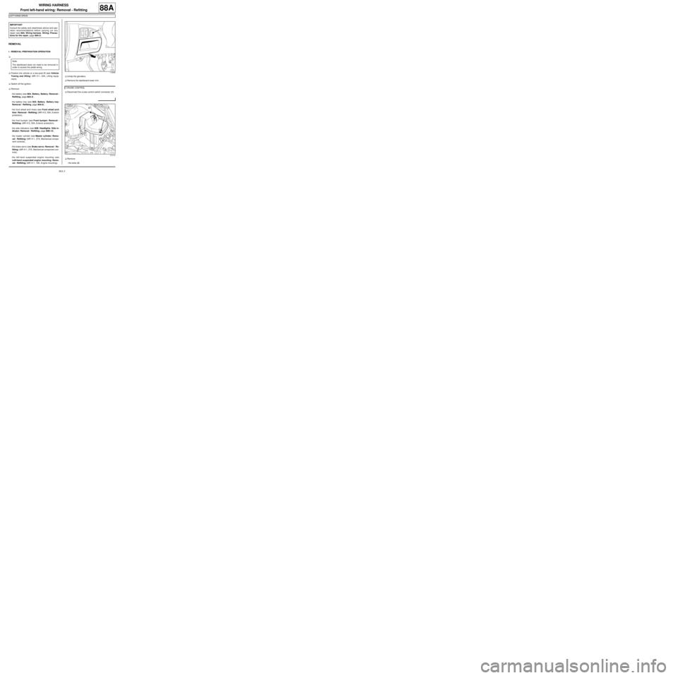
val - Refitting) (MR 411, 19D, Engine mounting).aUnclip the glovebox.
aRemove the dashboard lower trim.
aDisconnect the cruise control switch connector (1) .
aRemove:
-the bolts (2) IMPORTANT
Consult the safety and cleanliness advice and ope-
ration recommendations before carrying out any
repair (see 88A, Wiring harness, Wiring: Precau-
tions for the repair, page 88A-2) .
Note:
The dashboard does not need to be removed in
order to access the pedal wiring.
119506
CRUISE CONTROL
121212
Page 143 of 241
88A-7
WIRING HARNESS
Front left-hand wiring: Removal - Refitting
LEFT-HAND DRIVE
88A
-the horn connector (13) ,
-the windscreen washer pump connector (14) ,
-the front left-hand side light connector (15) ,
-the front left-hand headlight connector (16) ,
-the front left-hand indicator connector (17) ,
-the headlight beam adjustment motor connectors
(18) ,
-the front right-hand wheel speed sensor connector
(19) ,
-the hydraulic brake unit connector (20) ,
-the injection computer connector (21) ,
-the front left-hand wheel speed sensor connector
(22) ,
-the front left-hand wiring/passenger compartment
wiring connectors (23) ,
-the clutch pedal position sensor connector (24) ,
-the STOP warning light switch connector (25) ,
-the acceleration pedal potentiometer connector
(26) .
aDisconnect the regulated additional heater connec-
tor (27) .
aRemove the additional heater earth wiring nut (28) .
aDisconnect the gearbox pump assembly relay con-
nector (29) .
aRemove:
-the earth wiring nut on the front right-hand side
member (30) ,
-the earth wiring nut on the front left-hand side
member (31) ,
-the earth wiring nut on the body (32) ,
-the hydraulic brake unit earth wiring nut (33) ,
-the earth wiring nut on the negative battery terminal
(34) ,
-the earth wiring nut on the bodywork (35) ,-the front windscreen wiper mechanism (see 85A,
Wiping - Washing, Windscreen wiper mecha-
nism: Removal - Refitting, page 85A-10) .
aUnclip:
-the section of wiring from the bulkhead,
-the section of wiring on the front bumper cross
member,
-the section of wiring from the windscreen washer
reservoir
-the section of wiring from the dashboard cross
member.
aUnclip the front left-hand wiring from the bulkhead.
aRemove the front left-hand wiring through the engi-
ne compartment.
REFITTING
I - REFITTING PREPARATIONS OPERATION
aIf replacing with a complete wiring harness, lock the
unused connectors (see Connectors: Sealing and
locking) (Technical Note 6015A, 88A, Wiring).
II - REFITTING OPERATION FOR PART
CONCERNED
aPosition the front left-hand wiring across the bulk-
head.
aClip the front left-hand wiring onto the bulkhead.
aConnect:
-the acceleration pedal potentiometer connector,
-the STOP warning light switch connector,
-the clutch pedal position sensor connector ,
-the front left-hand wiring/passenger compartment
wiring connectors,
-the injection computer connector,
-the front left-hand wheel speed sensor connector,
-the hydraulic brake unit connector,
-the front right-hand wheel speed sensor connector,
-the headlight beam adjustment motor connectors, CLIMATE CONTROL
JH1
WARNING
To prevent any damage during the removal ope-
ration, check that the wiring is free from its moun-
tings (retaining clip, plastic clip, adhesive tape,
connector, etc.).
Page 144 of 241
88A-8
WIRING HARNESS
Front left-hand wiring: Removal - Refitting
LEFT-HAND DRIVE
88A
-the front left-hand indicator connector,
-the front left-hand headlight connector,
-the front left-hand side light connector,
-the windscreen washer pump connector,
-the horn connector,
-the front right-hand side light connector,
-the front right-hand headlight connector,
-the front right-hand indicator connector.
aConnect the regulated additional heater connector.
aRefit the additional heater earth wiring nut.
aConnect the gearbox pump assembly relay connec-
tor.
aRefit:
-the windscreen wiper mechanism (see 85A, Wi-
ping - Washing, Windscreen wiper mechanism:
Removal - Refitting, page 85A-10) ,
-the earth wiring nut on the bodywork,
-the earth wiring nut on the negative battery termi-
nal,
-the hydraulic brake unit earth wiring nut,
-the earth wiring nut on the body,
-the earth wiring nut on the front left-hand side
member,
-the earth wiring nut on the front right-hand side
member,
aClip:
-the section of wiring onto the dashboard cross
member,
-the section of wiring onto the windscreen washer
reservoir
-the section of wiring onto the front bumper cross
member,
-the section of wiring onto the bulkhead.
aRefit the engine compartment connection unit nuts.aClip on:
-the fuse holders,
-the front left-hand wiring/engine harness connec-
tor.
aConnect the front left-hand wiring/engine harness
connector.
aRefit:
-the engine compartment connection unit supply wi-
ring nut,
-the fuses.
aClip on the engine compartment connection unit
board.
III - FINAL OPERATION
aRefit:
-the cover from the engine compartment connection
unit,
-the bolts.
aConnect the cruise control switch connector.
aRefit the dashboard lower trim.
aClip the glovebox in position.
aRefit:
-the left-hand suspended engine mounting (see
Left-hand suspended engine mounting: Remo-
val - Refitting) (MR 411, 19D, Engine mounting),
-the brake servo (see Brake servo: Removal - Re-
fitting) (MR 411, 37A, Mechanical component con-
trols),
-the master cylinder (see Master cylinder: Remo-
val - Refitting) (MR 411, 37A, Mechanical compo-
nent controls),
-the side indicators (see 80B, Headlights, Side in-
dicator: Removal - Refitting, page 80B-13) ,
-the front bumper (see Front bumper: Removal -
Refitting) (MR 412, 55A, Exterior protection), CLIMATE CONTROL
JH1
WARNING
To prevent damage to the wiring har ness when
refitting, obser ve the original routing.
CRUISE CONTROL
Page 179 of 241
88A-43
WIRING HARNESS
Passenger compartment wiring: Connector access
LEFT-HAND DRIVE
88A
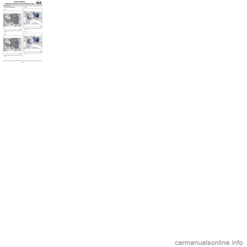
I - LOCATION OF CONNECTORS
1 - R 107
aR 107 connectors (Dashboard / front of engine con-
nection).
2 - R 99
aR 99 connector (Dashboard / heating system con-
nection).3 - R 301
aR 301 connectors (Dashboard / interior lights con-
nection).
4 - R 3
aR 3 connector (Dashboard / driver's door connec-
tion).
122341
122341
122345
122345
Page 180 of 241
88A-44
WIRING HARNESS
Passenger compartment wiring: Connector access
LEFT-HAND DRIVE
88A
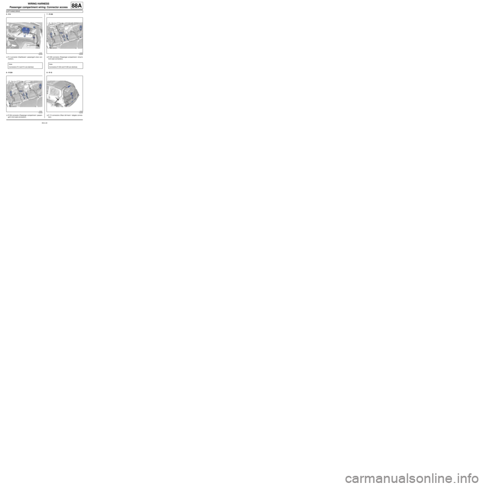
5 - R 4
aR 4 connector (Dashboard / passenger's door con-
nection).
6 - R 334
aR 334 connector (Passenger compartment / passen-
ger's front seat connection).7 - R 335
aR 335 connector (Passenger compartment / driver's
front seat connection).
8 - R 15
aR 15 connectors (Rear left-hand / tailgate connec-
tion).
122346
Note:
Connectors R 3 and R 4 are identical.
122349
122349
Note:
Connectors R 334 and R 335 are identical.
122356
Page 181 of 241
88A-45
WIRING HARNESS
Passenger compartment wiring: Connector access
LEFT-HAND DRIVE
88A
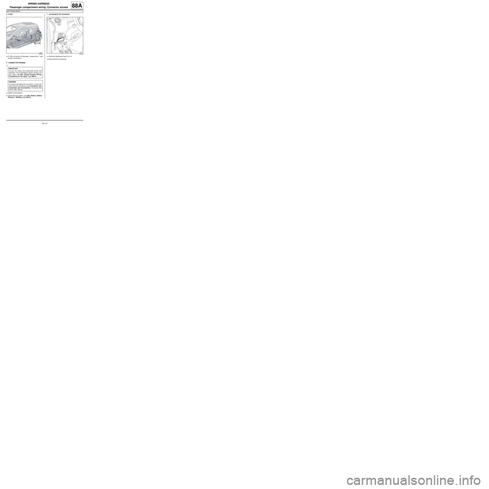
9 - R 259
aR 259 connectors (Passenger compartment / rear
bumper connection).
II - CONNECTOR OPENING
a
aSwitch off the ignition.
aDisconnect the battery (see 80A, Battery, Battery:
Removal - Refitting, page 80A-2) .1 - Accessing R 107 connectors
aUnclip the dashboard lower trim (1) .
aDisconnect the connectors.
122354
IMPORTANT
Consult the safety and cleanliness advice and
operation recommendations before carrying out
any repair (see 88A, Wiring harness, Wiring:
Precautions for the repair, page 88A-2) .
WARNING
To prevent damaging the connectors, consult the
disconnection procedures (see Connector: Dis-
connection and reconnection) (Technical Note
6015A, 88A, Wiring).
120278